Engineering LibreTexts

10.1: Momentum of a Particle

  • Page ID
    47280
    • Franz S. Hover & Michael S. Triantafyllou
    • Massachusetts Institute of Technology via MIT OpenCourseWare
    \( \newcommand{\vecs}[1]{\overset { \scriptstyle \rightharpoonup} {\mathbf{#1}} } \) \( \newcommand{\vecd}[1]{\overset{-\!-\!\rightharpoonup}{\vphantom{a}\smash {#1}}} \)\(\newcommand{\id}{\mathrm{id}}\) \( \newcommand{\Span}{\mathrm{span}}\) \( \newcommand{\kernel}{\mathrm{null}\,}\) \( \newcommand{\range}{\mathrm{range}\,}\) \( \newcommand{\RealPart}{\mathrm{Re}}\) \( \newcommand{\ImaginaryPart}{\mathrm{Im}}\) \( \newcommand{\Argument}{\mathrm{Arg}}\) \( \newcommand{\norm}[1]{\| #1 \|}\) \( \newcommand{\inner}[2]{\langle #1, #2 \rangle}\) \( \newcommand{\Span}{\mathrm{span}}\) \(\newcommand{\id}{\mathrm{id}}\) \( \newcommand{\Span}{\mathrm{span}}\) \( \newcommand{\kernel}{\mathrm{null}\,}\) \( \newcommand{\range}{\mathrm{range}\,}\) \( \newcommand{\RealPart}{\mathrm{Re}}\) \( \newcommand{\ImaginaryPart}{\mathrm{Im}}\) \( \newcommand{\Argument}{\mathrm{Arg}}\) \( \newcommand{\norm}[1]{\| #1 \|}\) \( \newcommand{\inner}[2]{\langle #1, #2 \rangle}\) \( \newcommand{\Span}{\mathrm{span}}\)\(\newcommand{\AA}{\unicode[.8,0]{x212B}}\)

    We consider the rigid body dynamics with a coordinate system affixed on the body. We will develop equations useful for the simulation of vehicles, as well as for understanding the signals measured by an inertial measurement unit (IMU).

    A common frame for boats, submarines, aircraft, terrestrial wheeled and other vehicles has the body-referenced \(x\)-axis forward, \(y\)-axis to port (left), and \(z\)-axis up. This will be the sense of our body-referenced coordinate system here.
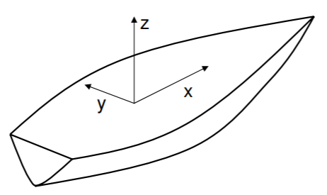
    Graphic showing the standard body-referenced coordinate system on a vehicle such as a boat: x is forwards, y is to the left, z is upwards.
    Figure \(\PageIndex{1}\): Convention for the body-referenced coordinate system on a vehicle: \(x\) is forward, \(y\) is sway to the left, and \(z\) is heave upwards. Looking forward from the vehicle ”helm,” roll about the \(x\) axis is positive counterclockwise, pitch about the \(y\)-axis is positive bow-down, and yaw about the \(z\)-axis is positive turning left.

    Since the body moves with respect to an inertial frame, dynamics expressed in the body-referenced frame need extra attention. First, linear momentum for a particle obeys the equality \[ \vec{F} \, = \, \dfrac{d}{dt} (m \vec{v}). \]

    A rigid body consists of a large number of these small particles, which can be indexed. The summations we use below can be generalized to integrals quite easily. We have \[ \vec{F_i} + \vec{R_i} \, = \, \dfrac{d}{dt} (m_i \vec{v}_i), \]where \(\vec{F}_i\) is the external force acting on the particle and \(\vec{R}_i\) is the net force exerted by all the other surrounding particles (internal forces). Since the collection of particles is not driven apart by the internal forces, we must have equal and opposite internal forces such that \[ \sum_{i=1}^N \vec{R}_i \, = \, 0.\]Then summing up all the particle momentum equations gives \[ \sum_{i=1}^N \vec{F}_i \, = \, \sum_{i=1}^N \dfrac{d}{dt} (m_i \vec{v}_i). \]

    Note that the particle velocities are not independent, because the particles are rigidly attached.

    Now consider a body reference frame, with origin \(0\), in which the particle \(i\) resides at body-referenced radius vector \(\vec{r}\); the body translates and rotates, and we now consider how the momentum equation depends on this motion.


    This page titled 10.1: Momentum of a Particle is shared under a CC BY-NC-SA 4.0 license and was authored, remixed, and/or curated by Franz S. Hover & Michael S. Triantafyllou (MIT OpenCourseWare) via source content that was edited to the style and standards of the LibreTexts platform; a detailed edit history is available upon request.