Chapter 5: Controls and Robotics
- Page ID
- 107044
\( \newcommand{\vecs}[1]{\overset { \scriptstyle \rightharpoonup} {\mathbf{#1}} } \)
\( \newcommand{\vecd}[1]{\overset{-\!-\!\rightharpoonup}{\vphantom{a}\smash {#1}}} \)
\( \newcommand{\dsum}{\displaystyle\sum\limits} \)
\( \newcommand{\dint}{\displaystyle\int\limits} \)
\( \newcommand{\dlim}{\displaystyle\lim\limits} \)
\( \newcommand{\id}{\mathrm{id}}\) \( \newcommand{\Span}{\mathrm{span}}\)
( \newcommand{\kernel}{\mathrm{null}\,}\) \( \newcommand{\range}{\mathrm{range}\,}\)
\( \newcommand{\RealPart}{\mathrm{Re}}\) \( \newcommand{\ImaginaryPart}{\mathrm{Im}}\)
\( \newcommand{\Argument}{\mathrm{Arg}}\) \( \newcommand{\norm}[1]{\| #1 \|}\)
\( \newcommand{\inner}[2]{\langle #1, #2 \rangle}\)
\( \newcommand{\Span}{\mathrm{span}}\)
\( \newcommand{\id}{\mathrm{id}}\)
\( \newcommand{\Span}{\mathrm{span}}\)
\( \newcommand{\kernel}{\mathrm{null}\,}\)
\( \newcommand{\range}{\mathrm{range}\,}\)
\( \newcommand{\RealPart}{\mathrm{Re}}\)
\( \newcommand{\ImaginaryPart}{\mathrm{Im}}\)
\( \newcommand{\Argument}{\mathrm{Arg}}\)
\( \newcommand{\norm}[1]{\| #1 \|}\)
\( \newcommand{\inner}[2]{\langle #1, #2 \rangle}\)
\( \newcommand{\Span}{\mathrm{span}}\) \( \newcommand{\AA}{\unicode[.8,0]{x212B}}\)
\( \newcommand{\vectorA}[1]{\vec{#1}} % arrow\)
\( \newcommand{\vectorAt}[1]{\vec{\text{#1}}} % arrow\)
\( \newcommand{\vectorB}[1]{\overset { \scriptstyle \rightharpoonup} {\mathbf{#1}} } \)
\( \newcommand{\vectorC}[1]{\textbf{#1}} \)
\( \newcommand{\vectorD}[1]{\overrightarrow{#1}} \)
\( \newcommand{\vectorDt}[1]{\overrightarrow{\text{#1}}} \)
\( \newcommand{\vectE}[1]{\overset{-\!-\!\rightharpoonup}{\vphantom{a}\smash{\mathbf {#1}}}} \)
\( \newcommand{\vecs}[1]{\overset { \scriptstyle \rightharpoonup} {\mathbf{#1}} } \)
\(\newcommand{\longvect}{\overrightarrow}\)
\( \newcommand{\vecd}[1]{\overset{-\!-\!\rightharpoonup}{\vphantom{a}\smash {#1}}} \)
\(\newcommand{\avec}{\mathbf a}\) \(\newcommand{\bvec}{\mathbf b}\) \(\newcommand{\cvec}{\mathbf c}\) \(\newcommand{\dvec}{\mathbf d}\) \(\newcommand{\dtil}{\widetilde{\mathbf d}}\) \(\newcommand{\evec}{\mathbf e}\) \(\newcommand{\fvec}{\mathbf f}\) \(\newcommand{\nvec}{\mathbf n}\) \(\newcommand{\pvec}{\mathbf p}\) \(\newcommand{\qvec}{\mathbf q}\) \(\newcommand{\svec}{\mathbf s}\) \(\newcommand{\tvec}{\mathbf t}\) \(\newcommand{\uvec}{\mathbf u}\) \(\newcommand{\vvec}{\mathbf v}\) \(\newcommand{\wvec}{\mathbf w}\) \(\newcommand{\xvec}{\mathbf x}\) \(\newcommand{\yvec}{\mathbf y}\) \(\newcommand{\zvec}{\mathbf z}\) \(\newcommand{\rvec}{\mathbf r}\) \(\newcommand{\mvec}{\mathbf m}\) \(\newcommand{\zerovec}{\mathbf 0}\) \(\newcommand{\onevec}{\mathbf 1}\) \(\newcommand{\real}{\mathbb R}\) \(\newcommand{\twovec}[2]{\left[\begin{array}{r}#1 \\ #2 \end{array}\right]}\) \(\newcommand{\ctwovec}[2]{\left[\begin{array}{c}#1 \\ #2 \end{array}\right]}\) \(\newcommand{\threevec}[3]{\left[\begin{array}{r}#1 \\ #2 \\ #3 \end{array}\right]}\) \(\newcommand{\cthreevec}[3]{\left[\begin{array}{c}#1 \\ #2 \\ #3 \end{array}\right]}\) \(\newcommand{\fourvec}[4]{\left[\begin{array}{r}#1 \\ #2 \\ #3 \\ #4 \end{array}\right]}\) \(\newcommand{\cfourvec}[4]{\left[\begin{array}{c}#1 \\ #2 \\ #3 \\ #4 \end{array}\right]}\) \(\newcommand{\fivevec}[5]{\left[\begin{array}{r}#1 \\ #2 \\ #3 \\ #4 \\ #5 \\ \end{array}\right]}\) \(\newcommand{\cfivevec}[5]{\left[\begin{array}{c}#1 \\ #2 \\ #3 \\ #4 \\ #5 \\ \end{array}\right]}\) \(\newcommand{\mattwo}[4]{\left[\begin{array}{rr}#1 \amp #2 \\ #3 \amp #4 \\ \end{array}\right]}\) \(\newcommand{\laspan}[1]{\text{Span}\{#1\}}\) \(\newcommand{\bcal}{\cal B}\) \(\newcommand{\ccal}{\cal C}\) \(\newcommand{\scal}{\cal S}\) \(\newcommand{\wcal}{\cal W}\) \(\newcommand{\ecal}{\cal E}\) \(\newcommand{\coords}[2]{\left\{#1\right\}_{#2}}\) \(\newcommand{\gray}[1]{\color{gray}{#1}}\) \(\newcommand{\lgray}[1]{\color{lightgray}{#1}}\) \(\newcommand{\rank}{\operatorname{rank}}\) \(\newcommand{\row}{\text{Row}}\) \(\newcommand{\col}{\text{Col}}\) \(\renewcommand{\row}{\text{Row}}\) \(\newcommand{\nul}{\text{Nul}}\) \(\newcommand{\var}{\text{Var}}\) \(\newcommand{\corr}{\text{corr}}\) \(\newcommand{\len}[1]{\left|#1\right|}\) \(\newcommand{\bbar}{\overline{\bvec}}\) \(\newcommand{\bhat}{\widehat{\bvec}}\) \(\newcommand{\bperp}{\bvec^\perp}\) \(\newcommand{\xhat}{\widehat{\xvec}}\) \(\newcommand{\vhat}{\widehat{\vvec}}\) \(\newcommand{\uhat}{\widehat{\uvec}}\) \(\newcommand{\what}{\widehat{\wvec}}\) \(\newcommand{\Sighat}{\widehat{\Sigma}}\) \(\newcommand{\lt}{<}\) \(\newcommand{\gt}{>}\) \(\newcommand{\amp}{&}\) \(\definecolor{fillinmathshade}{gray}{0.9}\)Pre-recroded videos that cover these topics can be found in the YouTube playlist here: https://www.youtube.com/playlist?lis...pRLnulPYtfcwL4.
Introduction to Controls and Robotics
Controls and Robotics is a critical subdiscipline of mechanical engineering. There is an entire series of courses that you will soon explore in these topics that are extremely useful like PID control systems but we will explore some concepts of controls, robotics, navigation, and programming using Arduinos and Parallax BOE shields.
This is just meant as a very very broad introduction to robotics and controls and to have some fun as well!!
Prototype and LED Control
Before we start designing cool robotics systems and applications we first need to get use to working with the Arduino interface, how to program with Arduino, and then to connect to our systems.
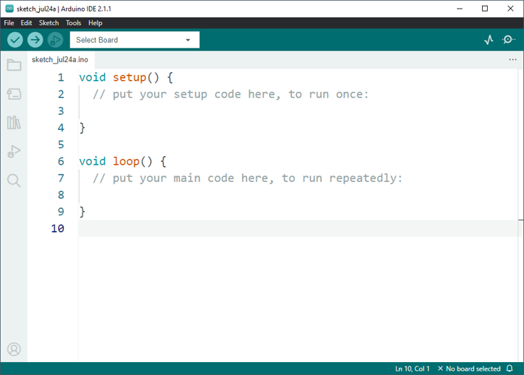
Let’s first look at the Arduino software as seen in Fig.1

Figure \(\PageIndex{1}\): Arduino Software.
The check in the upper left hand corner is a button you should push once you have written your code to verify the code and to see if there are any immediate error messages. I fyou click the arrow that points the right next to check will actually run the code and send it to the Arduino when connected. It is also important that whensending the code to the Arduino UNO board you select that board as well. You will also notice that there are two sections
• Void setup
• Void loop
The setup will contain code and statements and will execute any statements within this but only once. This code is run first and then moves to the next section, i.e. the loop. The loop will run that code repeatedly and continuously and forever so it is distinct from the setup section. Typically this will contain the main behavior of the program. After these two main sections you can typically create functions below these sections and you can make definitions or initializations above the setup section as well.
So let’s start to build our first test bed and prototype a blinking LED control and we can see the circuit pins here in Fig.2 and the LED has an anode lead that is longer than the cathode end which should be connected to the ground.

Figure \(\PageIndex{2}\): LED Pin Board
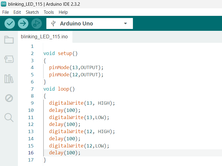
We can note start to build our Arduino code and we need to set pin 12 and 13 as our output within the setup and then in the loop we can set the LED to turn on and turn off as seen in Fig.3.
In the delay function that is time in ms and when the write is high the voltage is 5V and when it is low the voltage will be set to 0V.
This was a fantastic proof of concept but now we can move to working with our Servo Motors!.
Controlling Servo Motors

Figure \(\PageIndex{3}\): LED Arduino Code.
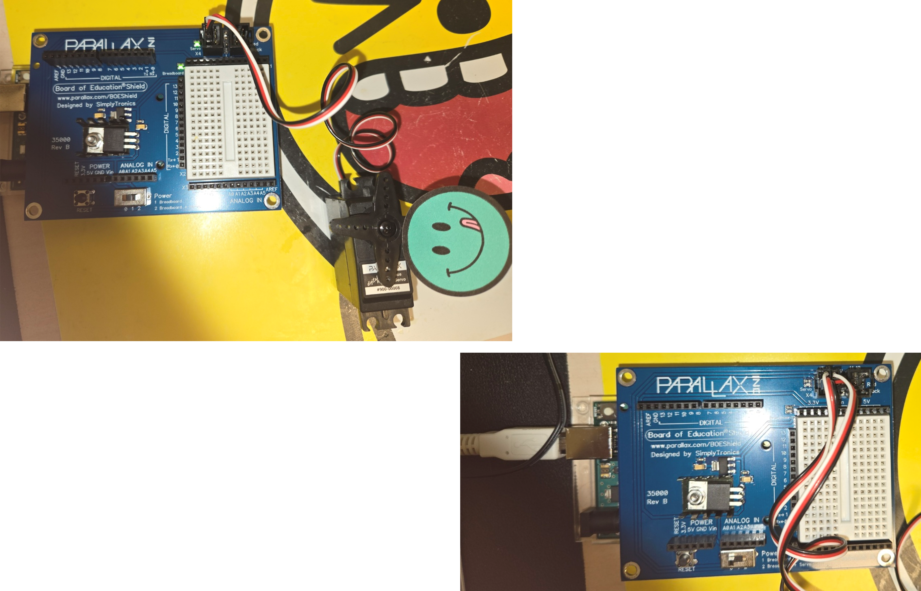
Now let’s start to control motors specifically our Servo Motors. This will be critical to drive and navigate our robot but first we need to connect the motors to our board as seen in Fig.4

Figure \(\PageIndex{4}\): Servo Motor Pin Board.
We are connecting these motors to Pin 12 and 13 here and we will have to do the following steps
• Include Servo Library
• Declare the Servo Motor
• Attach the Servo Motor to pin 12 or 13
• writeMicroseconds a value of 1500 will stay still, 1300 will go clockwise, and 1700 will go counter-clockwise
It is important that you may have to use a screwdriver to adjust the servomotor to ensure they do not turn when at a value of 1500. We can make the motors turn CW, CCW, pause, and then alternate as seen in Fig.5.

Figure \(\PageIndex{5}\): Servo Motor Sketch.
Bot Navigation
Now that we have done our initial testing we can build our robot!! Be sure to follow the steps in our video and it should look like Fig.6.

Figure \(\PageIndex{6}\): Robot Image.
We can drive the robot using the same functions that we worked with previously to drive the robot forward, backward, turn right, turn left, pivot right, and pivot left in Fig.7.

Figure \(\PageIndex{7}\): Drive Robot Sketch.
We can also use a for loop to ramp up the speed the robot as seen in Fig.8

Figure \(\PageIndex{8}\): Ramp Up Robot Speed Sketch.
Whisker Navigation
We can now begin to program and combine some more complex navigation protocols to our robot but we also want our robot to navigate autonomously. However to do that we will have to add some additional sensors to provide feedback to guide navigation there are a number of sensors that we can choose from but we will illustrate a whisker navigation technique as well as a light sensitive navigation technique.
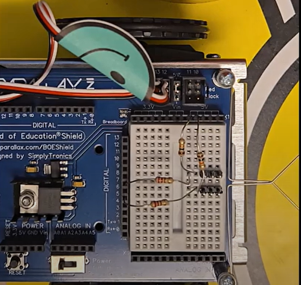
The whiskers work by either applying a 5V or if they are pressed and touch our 3 pin headers then the circuit applies 0 V. So we can utilize this digital readout that occurs if the whiskers physically run into something to change the direction of our robot. We can see our fully built robot here in Fig.9

Figure \(\PageIndex{9}\): Whisker Robot.
We can utilize if and else if function logic to navigate the robot here and we can demo this in class and in our videos.
Light Sensitive Navigation
We can also use a light sensor on our robot as seen here in Fig.10 and some of the same protocols we developed previously to move either toward or away from light.

Figure \(\PageIndex{10}\): Light Robot Robot.
We can also navigate our robot with a camera as well as LED sensors to do things like park, follow lines, or navigate a maze as well.

