
2.4.3: Simplifying Series-Parallel Components
- Page ID
- 52901

\( \newcommand{\vecs}[1]{\overset { \scriptstyle \rightharpoonup} {\mathbf{#1}} } \)
\( \newcommand{\vecd}[1]{\overset{-\!-\!\rightharpoonup}{\vphantom{a}\smash {#1}}} \)
\( \newcommand{\id}{\mathrm{id}}\) \( \newcommand{\Span}{\mathrm{span}}\)
( \newcommand{\kernel}{\mathrm{null}\,}\) \( \newcommand{\range}{\mathrm{range}\,}\)
\( \newcommand{\RealPart}{\mathrm{Re}}\) \( \newcommand{\ImaginaryPart}{\mathrm{Im}}\)
\( \newcommand{\Argument}{\mathrm{Arg}}\) \( \newcommand{\norm}[1]{\| #1 \|}\)
\( \newcommand{\inner}[2]{\langle #1, #2 \rangle}\)
\( \newcommand{\Span}{\mathrm{span}}\)
\( \newcommand{\id}{\mathrm{id}}\)
\( \newcommand{\Span}{\mathrm{span}}\)
\( \newcommand{\kernel}{\mathrm{null}\,}\)
\( \newcommand{\range}{\mathrm{range}\,}\)
\( \newcommand{\RealPart}{\mathrm{Re}}\)
\( \newcommand{\ImaginaryPart}{\mathrm{Im}}\)
\( \newcommand{\Argument}{\mathrm{Arg}}\)
\( \newcommand{\norm}[1]{\| #1 \|}\)
\( \newcommand{\inner}[2]{\langle #1, #2 \rangle}\)
\( \newcommand{\Span}{\mathrm{span}}\) \( \newcommand{\AA}{\unicode[.8,0]{x212B}}\)
\( \newcommand{\vectorA}[1]{\vec{#1}} % arrow\)
\( \newcommand{\vectorAt}[1]{\vec{\text{#1}}} % arrow\)
\( \newcommand{\vectorB}[1]{\overset { \scriptstyle \rightharpoonup} {\mathbf{#1}} } \)
\( \newcommand{\vectorC}[1]{\textbf{#1}} \)
\( \newcommand{\vectorD}[1]{\overrightarrow{#1}} \)
\( \newcommand{\vectorDt}[1]{\overrightarrow{\text{#1}}} \)
\( \newcommand{\vectE}[1]{\overset{-\!-\!\rightharpoonup}{\vphantom{a}\smash{\mathbf {#1}}}} \)
\( \newcommand{\vecs}[1]{\overset { \scriptstyle \rightharpoonup} {\mathbf{#1}} } \)
\( \newcommand{\vecd}[1]{\overset{-\!-\!\rightharpoonup}{\vphantom{a}\smash {#1}}} \)
\(\newcommand{\avec}{\mathbf a}\) \(\newcommand{\bvec}{\mathbf b}\) \(\newcommand{\cvec}{\mathbf c}\) \(\newcommand{\dvec}{\mathbf d}\) \(\newcommand{\dtil}{\widetilde{\mathbf d}}\) \(\newcommand{\evec}{\mathbf e}\) \(\newcommand{\fvec}{\mathbf f}\) \(\newcommand{\nvec}{\mathbf n}\) \(\newcommand{\pvec}{\mathbf p}\) \(\newcommand{\qvec}{\mathbf q}\) \(\newcommand{\svec}{\mathbf s}\) \(\newcommand{\tvec}{\mathbf t}\) \(\newcommand{\uvec}{\mathbf u}\) \(\newcommand{\vvec}{\mathbf v}\) \(\newcommand{\wvec}{\mathbf w}\) \(\newcommand{\xvec}{\mathbf x}\) \(\newcommand{\yvec}{\mathbf y}\) \(\newcommand{\zvec}{\mathbf z}\) \(\newcommand{\rvec}{\mathbf r}\) \(\newcommand{\mvec}{\mathbf m}\) \(\newcommand{\zerovec}{\mathbf 0}\) \(\newcommand{\onevec}{\mathbf 1}\) \(\newcommand{\real}{\mathbb R}\) \(\newcommand{\twovec}[2]{\left[\begin{array}{r}#1 \\ #2 \end{array}\right]}\) \(\newcommand{\ctwovec}[2]{\left[\begin{array}{c}#1 \\ #2 \end{array}\right]}\) \(\newcommand{\threevec}[3]{\left[\begin{array}{r}#1 \\ #2 \\ #3 \end{array}\right]}\) \(\newcommand{\cthreevec}[3]{\left[\begin{array}{c}#1 \\ #2 \\ #3 \end{array}\right]}\) \(\newcommand{\fourvec}[4]{\left[\begin{array}{r}#1 \\ #2 \\ #3 \\ #4 \end{array}\right]}\) \(\newcommand{\cfourvec}[4]{\left[\begin{array}{c}#1 \\ #2 \\ #3 \\ #4 \end{array}\right]}\) \(\newcommand{\fivevec}[5]{\left[\begin{array}{r}#1 \\ #2 \\ #3 \\ #4 \\ #5 \\ \end{array}\right]}\) \(\newcommand{\cfivevec}[5]{\left[\begin{array}{c}#1 \\ #2 \\ #3 \\ #4 \\ #5 \\ \end{array}\right]}\) \(\newcommand{\mattwo}[4]{\left[\begin{array}{rr}#1 \amp #2 \\ #3 \amp #4 \\ \end{array}\right]}\) \(\newcommand{\laspan}[1]{\text{Span}\{#1\}}\) \(\newcommand{\bcal}{\cal B}\) \(\newcommand{\ccal}{\cal C}\) \(\newcommand{\scal}{\cal S}\) \(\newcommand{\wcal}{\cal W}\) \(\newcommand{\ecal}{\cal E}\) \(\newcommand{\coords}[2]{\left\{#1\right\}_{#2}}\) \(\newcommand{\gray}[1]{\color{gray}{#1}}\) \(\newcommand{\lgray}[1]{\color{lightgray}{#1}}\) \(\newcommand{\rank}{\operatorname{rank}}\) \(\newcommand{\row}{\text{Row}}\) \(\newcommand{\col}{\text{Col}}\) \(\renewcommand{\row}{\text{Row}}\) \(\newcommand{\nul}{\text{Nul}}\) \(\newcommand{\var}{\text{Var}}\) \(\newcommand{\corr}{\text{corr}}\) \(\newcommand{\len}[1]{\left|#1\right|}\) \(\newcommand{\bbar}{\overline{\bvec}}\) \(\newcommand{\bhat}{\widehat{\bvec}}\) \(\newcommand{\bperp}{\bvec^\perp}\) \(\newcommand{\xhat}{\widehat{\xvec}}\) \(\newcommand{\vhat}{\widehat{\vvec}}\) \(\newcommand{\uhat}{\widehat{\uvec}}\) \(\newcommand{\what}{\widehat{\wvec}}\) \(\newcommand{\Sighat}{\widehat{\Sigma}}\) \(\newcommand{\lt}{<}\) \(\newcommand{\gt}{>}\) \(\newcommand{\amp}{&}\) \(\definecolor{fillinmathshade}{gray}{0.9}\)We can go beyond the simple observations presented above. Precisely how we approach this will depend on the components represented by the blocks (most often resistors, but possibly a voltage source or a current source) and how they are wired together. For starters, if all of the items in a sub-circuit are of the same type, they can just be combined using the techniques discussed in the previous chapters. Resistors in series are added, as are voltage sources in series-being wary of polarity. Resistors in parallel are combined using conductance or the product-sum rule while parallel current sources are added, again being wary of polarity. Things get a little trickier when there is a mix, such as two resistors in series with a voltage source, or a resistor in parallel with a couple of current sources. Precisely how this sort of situation is handled will become apparent shortly.
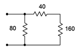
Figure 5.3.1 : A simple series-parallel resistor network.
To illustrate, let us consider the resistor configuration presented in Figure 5.3.1 . Imagine that an ohmmeter is connected to the two open terminals. What would it read? The ohmmeter would apply a small current to the circuit to determine the effective resistance of the group. The three resistors pictured here are not a simple series configuration because we can identify a current split at the 40 \(\Omega\) and 80 \(\Omega\) resistors. Similarly, it is not a parallel network because the 40 \(\Omega\) and 160 \(\Omega\) resistors are not both tied to the same two nodes. What we can say is that the 40 \(\Omega\) and 160 \(\Omega\) resistors are in series with each other as they must each see the same current. Thus, we can combine the two into a single equivalent resistance of 200 \(\Omega\). This equivalent is in parallel with the 80 \(\Omega\) resistor and 80 \(||\) 200 is approximately 57.14 \(\Omega\). That's what the ohmmeter should read. Indeed, wherever we see this configuration with these precise values, we can replace it with a single resistor of 57.14 \(\Omega\).
The simplification technique can be outlined as follows:
- Identify subgroups of resistors that exhibit series or parallel configurations within themselves.
- Replace the subgroups with a single equivalent resistance.
- Repeat the above steps until the circuit is reduced to a single resistance, or alternately, a simple series-only or parallel-only configuration.
The looping nature of the technique outlined above may need to be invoked many times, depending on the complexity of the network. In simpler networks, a single pass may be sufficient. Initially, it may be wise to redraw the circuit for each iteration of the loop. Eventually, with practice, this will not be needed except with the most complex networks. Let's look at a somewhat more involved example.
A series-parallel resistor network is shown in Figure 5.3.2 . Determine its equivalent resistance.
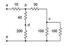
Figure 5.3.2 : Network for Example 5.3.1 .
The first step is to recognize those subgroups that are in series or in parallel with themselves. One obvious candidate is that the two 100 \(\Omega\) resistors are in parallel with each other. Two resistors of equal value in parallel are equivalent to half the resistance, or 50 \(\Omega\) in this case.
The other candidate is the 40 \(\Omega\), 200 \(\Omega\) pair. These are in series. The equivalent resistance of the pair is the series combination, or 240 \(\Omega\).
There are no other subsets of resistors that can be reduced (yet). The network is redrawn in Figure 5.3.3 with the equivalent resistances. The process is now repeated.
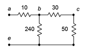
Figure 5.3.3 : Partially simplified network.
In the newly reduced network, the 50 \(\Omega\) and 30 \(\Omega\) resistances are in series, yielding 80 \(\Omega\).
Without redrawing, the process may be repeated again, this time the 240 \(\Omega\) being in parallel with the new 80 \(\Omega\) equivalent. 240 \(||\) 80 is equal to 60 \(\Omega\). This sequence has reduced the three right-most resistances down to one: the new 60 \(\Omega\) equivalent.
Finally, the 60 \(\Omega\) equivalent is in series with the 10 \(\Omega\) resistor, yielding a final equivalent resistance of 70 \(\Omega\).
Ladders
A ladder is a unique series-parallel configuration. It is arranged in a cascade of series and parallel connections. Ladders are used in a variety of applications, one of which will be examined in the next section.
The name is obvious based on the appearance of the network. An example resistive ladder network is shown in Figure 5.3.4 . The main thing to note is that the ladder network consists of “sections loading sections” repeatedly. By loading, we mean that this element (the load) draws off current and power from the prior section. As a result, simple two-resistor voltage dividers cannot be used. For example, it is a common error to assume that \(R_1\) and \(R_2\) create a voltage divider which can be used to determine \(V_{bf}\) if \(V_{af}\) is known. Similarly, the uninitiated may believe incorrectly that \(R_3\) and \(R_4\), or \(R_5\) and \(R_6\) create voltage dividers.
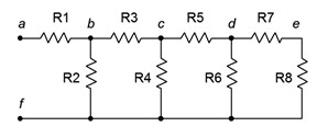
Figure 5.3.4 : A resistive ladder network.
In fact, the only proper voltage divider in this configuration is between \(R_7\) and \(R_8\). The reason for this becomes apparent if we imagine determining the equivalent resistance of the network by placing an ohmmeter at terminals \(a\) and \(f\). The ohmmeter will apply a current to node \(a\) which passes through \(R_1\). At node \(b\) this current splits, part going down \(R_2\) and part continuing through \(R_3\). Clearly then, \(R_1\) and \(R_2\) are not in series as they do not see the same current. Further, the current that flows through \(R_3\) enters node \(c\) where it splits again, part down \(R_4\) with the remainder flowing through \(R_5\). Thus, \(R_3\) and \(R_4\) are not in series, either. The same sort of thing happens again at node \(d\). This would continue for as many rungs as are on the ladder, the sole exception being the final two resistors which are in series (\(R_7\) and \(R_8\) here).
How then do we find the equivalent resistance of this network? We begin at the end farthest from the open terminals. We have already noted that \(R_7\) and \(R_8\) are in series. This pair, if treated as a single resistance, is in parallel with \(R_6\), or \(R_6||(R_7+R_8)\). This group of three is in series with \(R_5\), yielding \(R_5+R_6||(R_7+R_8)\)1. This new group of four is in parallel with \(R_4\), yielding \(R_4||(R_5+R_6||(R_7+R+8))\). This group is in series with \(R_3\), and that new group is in turn in parallel with \(R_2\). Finally, that penultimate grouping is in series with \(R_1\). Therefore, the equivalent resistance of the network is \(R_1+R_2||(R_3+ R_4||(R_5+R_6||(R_7+R_8)))\). Surely, it is a tad tedious to compute the value, but particularly difficult. A word to the wise: if the goal is determine the voltages at the various nodes or the myriad branch currents, it will be helpful to keep track of the equivalent resistances of the various groupings. For example, if \(V_{cf}\) is known and the goal is to find \(V_{df}\), the voltage divider would be \(R_6||(R_7+R_8) / (R_5+R_6||(R_7+R_8))\).
A resistive ladder network is shown in Figure 5.3.5 . Determine its equivalent resistance.
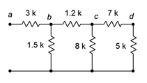
Figure 5.3.5 : Network for Example 5.3.2 .
Starting at the far end from the open terminals, we note that the 7 k\(\Omega\) and 5 k\(\Omega\) resistors are in series, yielding 12 k\(\Omega\). This is in parallel with the 8 k\(\Omega\). 12 k \(||\) 8 k is 4.8 k\(\Omega\). This is in series with the 1.2 k\(\Omega\) yielding 6 k\(\Omega\). The 6 k\(\Omega\) equivalent is in parallel with the 1.5 k\(\Omega\) which yields 1.2 k\(\Omega\).
Finally, the 1.2 k\(\Omega\) equivalent is in series with the 3 k\(\Omega\), yielding a final equivalent resistance of 4.2 k\(\Omega\).
Remember, always start at the far end and work toward the open terminals, i.e., the terminals into which you are trying to find the equivalent resistance.
A resistive ladder network is shown in Figure 5.3.6 . Determine its equivalent resistance.
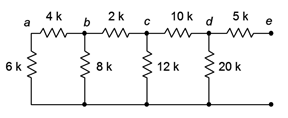
Figure 5.3.6 : Network for Example 5.3.3 .
The far end from the open terminals is the extreme left. First, the 6 k\(\Omega\) and 4 k\(\Omega\) resistors are in series, yielding 10 k\(\Omega\). This is in parallel with the 8 k\(\Omega\), achieving approximately 4.444 k\(\Omega\). In turn, this is in series with the 2 k\(\Omega\) yielding 6.444 k\(\Omega\). That result is in parallel with the 12 k\(\Omega\) which yields 4.193 k\(\Omega\). Placing this in series with the 10 k\(\Omega\) resistor yields 14.193 k\(\Omega\). This is in parallel with the 20 k\(\Omega\) yielding 8.302 k\(\Omega\).
Finally, the 8.302 k\(\Omega\) equivalent is in series with the 5 k\(\Omega\), yielding a final equivalent resistance of approximately 13.3 k\(\Omega\).
References
1Recall that \(||\) has higher precedence than + or –, therefore \(||\) is performed first, rather like multiplication when mixed with addition and subtraction.