
5.6: Exercises


- Last updated
- Jun 6, 2021
- Save as PDF

( \newcommand{\kernel}{\mathrm{null}\,}\)
Analysis
1. Given the circuit in Figure 7.6.1 , write the mesh loop equations.
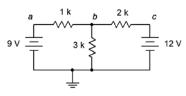
Figure 7.6.1
2. Using mesh analysis, determine the value of Vb for the circuit shown in Figure 7.6.1 .
3. For the circuit shown in Figure 7.6.1 , use mesh analysis to determine the current through the 1 kΩ resistor.
4. Given the circuit in Figure 7.6.2 , write the mesh loop equations and the associated determinants.
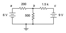
Figure 7.6.2
5. Using mesh analysis, determine the value of Vb for the circuit shown in Figure 7.6.2 .
6. For the circuit shown in Figure 7.6.2 , use mesh analysis to determine the current through the 500 Ω resistor.
7. Given the circuit in Figure 7.6.3 , write the mesh loop equations.
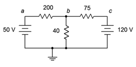
Figure 7.6.3
8. Using mesh analysis, determine the value of Vb for the circuit shown in Figure 7.6.3 .
9. For the circuit shown in Figure 7.6.3 , use mesh analysis to determine the current through the 75 Ω resistor.
10. Given the circuit in Figure 7.6.4 , write the mesh loop equations and the associated determinants.
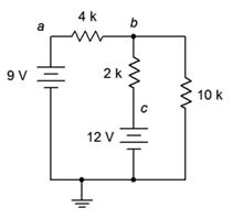
Figure 7.6.4
11. Using mesh analysis, determine the value of Vbc for the circuit shown in Figure 7.6.4 .
12. For the circuit shown in Figure 7.6.4 , use mesh analysis to determine the current through the 10 kΩ resistor.
13. Given the circuit in Figure 7.6.5 , write the mesh loop equations.
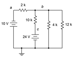
Figure 7.6.5
14. Using mesh analysis, determine the value of Vac for the circuit shown in Figure 7.6.5 .
15. For the circuit shown in Figure 7.6.5 , use mesh analysis to determine the current through the 4 kΩ resistor.
16. Given the circuit in Figure 7.6.6 , write the mesh loop equations and the associated determinants.
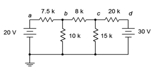
Figure 7.6.6
17. Using mesh analysis, determine the value of Vc for the circuit shown in Figure 7.6.6 .
18. For the circuit shown in Figure 7.6.6 , use mesh analysis to determine the current through the 10 kΩ resistor.
19. Given the circuit in Figure 7.6.7 , write the mesh loop equations.
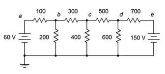
Figure 7.6.7
20. Using mesh analysis, determine the value of Vbd for the circuit shown in Figure 7.6.7 .
21. For the circuit shown in Figure 7.6.7 , use mesh analysis to determine the current through the 500 Ω resistor.
22. Given the circuit in Figure 7.6.8 , write the mesh loop equations.
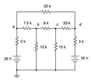
Figure 7.6.8
23. Using mesh analysis, determine the value of Vad for the circuit shown in Figure 7.6.8 .
24. For the circuit shown in Figure 7.6.8 , use mesh analysis to determine the current through the 3 kΩ resistor.
25. Given the circuit in Figure 7.6.9 , write the mesh loop equations.
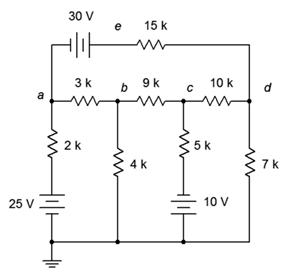
Figure 7.6.9
26. Using mesh analysis, determine the value of Ve for the circuit shown in Figure 7.6.9 .
27. For the circuit shown in Figure 7.6.9 , use mesh analysis to determine the current through the 9 kΩ resistor.
28. Given the circuit in Figure 7.6.10 , write the mesh loop equations and the associated determinants.
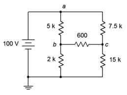
Figure 7.6.10
29. Using mesh analysis, determine the value of Vbc for the circuit shown in Figure 7.6.10 .
30. Given the circuit shown in Figure 7.6.10 , use mesh analysis to determine the current through the 600 Ω resistor.
31. Given the circuit in Figure 7.6.11 , write the mesh loop equations.
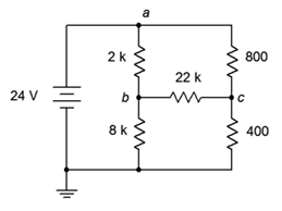
Figure 7.6.11
32. Using mesh analysis, determine the value of Vbc for the circuit shown in Figure 7.6.11 .
33. Given the circuit shown in Figure 7.6.11 , use mesh analysis to determine the current through the 800 Ω resistor.
34. For the circuit in Figure 7.6.12 , write the mesh loop equations.
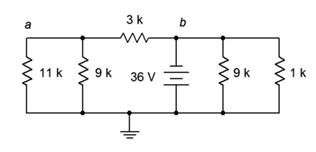
Figure 7.6.12
35. Using mesh analysis, determine the value of Va for the circuit shown in Figure 7.6.12 .
36. For the circuit shown in Figure 7.6.12 , use mesh analysis to determine the current through the 3 kΩ resistor.
37. Given the circuit in Figure 7.6.13 , write the mesh loop equations.
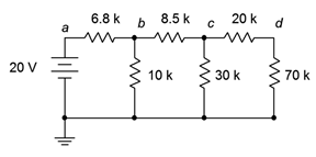
Figure 7.6.13
38. Using mesh analysis, determine the value of Vc for the circuit shown in Figure 7.6.13 .
39. For the circuit shown in Figure 7.6.13 , use mesh analysis to determine the current passing through the 8.5 kΩ resistor.
40. Given the circuit in Figure 7.6.14 , write the mesh loop equations (consider using source conversion).
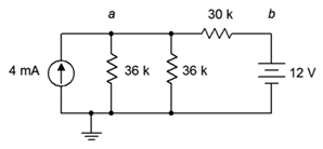
Figure 7.6.14
41. Using mesh analysis, determine the value of Va for the circuit shown in Figure 7.6.14 .
42. For the circuit shown in Figure 7.6.14 , use mesh analysis to determine the current passing through the 30 kΩ resistor.
43. Given the circuit in Figure 7.6.15 , write the mesh loop equations (consider using source conversion).
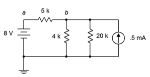
Figure 7.6.15
44. Using mesh analysis, determine the value of Vb for the circuit shown in Figure 7.6.15 .
45. For the circuit shown in Figure 7.6.15 , use mesh analysis to determine the current through the 5 kΩ resistor.
46. Given the circuit in Figure 7.6.16 , write the node equations.
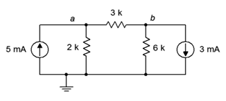
Figure 7.6.16
47. Using nodal analysis, determine the value of Vb for the circuit shown in Figure 7.6.16 .
48. For the circuit shown in Figure 7.6.16 , use nodal analysis to determine the current through the 3 kΩ resistor.
49. Given the circuit in Figure 7.6.17 , write the node equations.
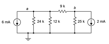
Figure 7.6.17
50. Using nodal analysis, determine the value of Vb for the circuit shown in Figure 7.6.17 .
51. For the circuit shown in Figure 7.6.17 , use nodal analysis to determine the current passing through the 12 kΩ resistor.
52. Given the circuit in Figure 7.6.18 , write the node equations.
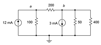
Figure 7.6.18
53. Using nodal analysis, determine the value of Vba for the circuit shown in Figure 7.6.18 .
54. For the circuit shown in Figure 7.6.18 , use nodal analysis to determine the current passing through the 100 Ω resistor.
55. Given the circuit in Figure 7.6.19 , write the node equations.
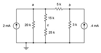
Figure 7.6.19
56. Using nodal analysis, determine the value of Vac for the circuit shown in Figure 7.6.19 .
57. For the circuit shown in Figure 7.6.19 , use nodal analysis to determine the current passing through the 20 kΩ resistor.
58. Given the circuit in Figure 7.6.20 , write the node equations.
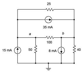
Figure 7.6.20
59. Using nodal analysis, determine the value of Vb for the circuit shown in Figure 7.6.20 .
60. For the circuit shown in Figure 7.6.20 , use nodal analysis to determine the current through the 3 kΩ resistor.
61. Given the circuit in Figure 7.6.21 , write the node equations.
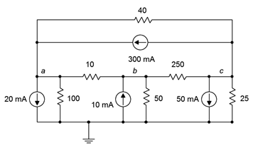
Figure 7.6.21
62. Using nodal analysis, determine the value of Vb for the circuit shown in Figure 7.6.21 .
63. For the circuit shown in Figure 7.6.21 , use nodal analysis to determine the current through the 40 Ω resistor.
64. Given the circuit in Figure 7.6.13 , write the node equations.
65. Using nodal analysis, determine the value of Vd for the circuit shown in Figure 7.6.13 .
66. For the circuit shown in Figure 7.6.13 , use nodal analysis to determine the current passing through the 20 kΩ resistor.
67. Given the circuit in Figure 7.6.14 , write the node equations using the general approach. Do not use source conversions.
68. Using nodal analysis, determine the value of Vab for the circuit shown in Figure 7.6.14 .
69. For the circuit shown in Figure 7.6.14 , use nodal analysis to determine the current passing through the 30 kΩ resistor.
70. Given the circuit in Figure 7.6.15 , write the node equations.
71. Using nodal analysis, determine the value of Vb for the circuit shown in Figure 7.6.15 .
72. For the circuit shown in Figure 7.6.15 , use nodal analysis to determine the current through the 4 kΩ resistor.
73. For the circuit of Figure 7.6.22 , determine Vb.
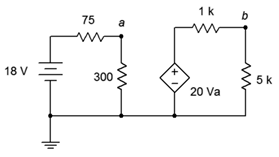
Figure 7.6.22
74. For the circuit of Figure 7.6.23 , determine Vc.
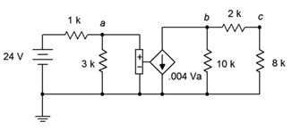
Figure 7.6.23
75. Given the circuit of Figure 7.6.24 , determine Vb.
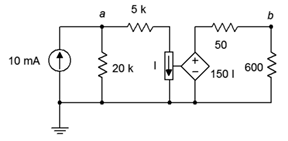
Figure 7.6.24
76. Find the current through the 10 kΩ resistor given the circuit of Figure 7.6.25 .
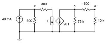
Figure 7.6.25
77. Given the circuit of Figure 7.6.26 , determine Vc.
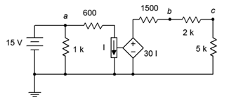
Figure 7.6.26
78. In the circuit of Figure 7.6.27 , determine Va.
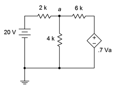
Figure 7.6.27
79. For the circuit of Figure 7.6.28 , determine Va.
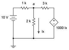
Figure 7.6.28
80. For the circuit of Figure 7.6.29 , determine Va.
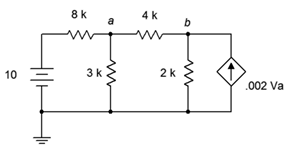
Figure 7.6.29
Challenge
81. Given the circuit in Figure 7.6.8 , write the node equations.
82. Using nodal analysis, determine the value of Vb for the circuit shown in Figure 7.6.8 .
83. For the circuit shown in Figure 7.6.8 , use nodal analysis to determine the current through the 3 kΩ resistor.
84. Given the circuit in Figure 7.6.6 , write the node equations.
85. Using nodal analysis, determine the value of Vc for the circuit shown in Figure 7.6.6 .
86. For the circuit shown in Figure 7.6.6 , use nodal analysis to determine the current through the 8 kΩ resistor.
87. Given the circuit in Figure 7.6.10 , write the node equations and the associated determinants.
88. Using nodal analysis, determine the value of Vbc for the circuit shown in Figure 7.6.10 .
89. For the circuit shown in Figure 7.6.10 , use nodal analysis to determine the current through the 2 kΩ resistor.
90. Given the circuit of Figure 7.6.30 , determine Vc.
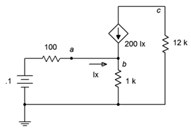
Figure 7.6.30
91. Find the current through the 10 kΩ resistor in the circuit of Figure 7.6.31 .

Figure 7.6.31
92. Given the circuit of Figure 7.6.32 , determine Vc.
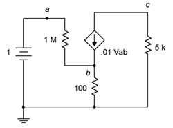
Figure 7.6.32
93. Given the circuit of Figure 7.6.33 , determine the current through the 5 kΩ resistor.
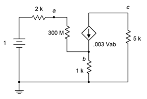
Figure 7.6.33
94. For the circuit of Figure 7.6.34 , determine Vb.
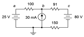
Figure 7.6.34
95. For the circuit of Figure 7.6.35 , determine Vc.
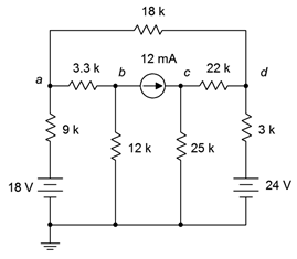
Figure 7.6.35
96. For the circuit of Figure 7.6.36 , determine Va.
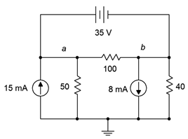
Figure 7.6.36
97. For the circuit of Figure 7.6.37 , determine Vb.
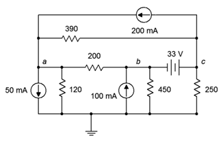
Figure 7.6.37
Simulation
98. Perform a DC bias simulation on the circuit depicted in Figure 7.6.7 to verify the component currents.
99. Perform a DC bias simulation on the circuit depicted in Figure 7.6.9 to verify the component currents.
100. Perform a DC bias simulation on the circuit depicted in Figure 7.6.7 to verify the loop currents and node voltages.
101. Perform a DC bias simulation on the circuit depicted in Figure 7.6.16 to verify the node voltages.
102. Perform a DC bias simulation on the circuit depicted in Figure 7.6.19 to verify the node voltages.
103. Perform a DC bias simulation on the circuit depicted in Figure 7.6.20 to verify the node voltages.