
12.8: Exercises
- Page ID
- 52975

\( \newcommand{\vecs}[1]{\overset { \scriptstyle \rightharpoonup} {\mathbf{#1}} } \)
\( \newcommand{\vecd}[1]{\overset{-\!-\!\rightharpoonup}{\vphantom{a}\smash {#1}}} \)
\( \newcommand{\dsum}{\displaystyle\sum\limits} \)
\( \newcommand{\dint}{\displaystyle\int\limits} \)
\( \newcommand{\dlim}{\displaystyle\lim\limits} \)
\( \newcommand{\id}{\mathrm{id}}\) \( \newcommand{\Span}{\mathrm{span}}\)
( \newcommand{\kernel}{\mathrm{null}\,}\) \( \newcommand{\range}{\mathrm{range}\,}\)
\( \newcommand{\RealPart}{\mathrm{Re}}\) \( \newcommand{\ImaginaryPart}{\mathrm{Im}}\)
\( \newcommand{\Argument}{\mathrm{Arg}}\) \( \newcommand{\norm}[1]{\| #1 \|}\)
\( \newcommand{\inner}[2]{\langle #1, #2 \rangle}\)
\( \newcommand{\Span}{\mathrm{span}}\)
\( \newcommand{\id}{\mathrm{id}}\)
\( \newcommand{\Span}{\mathrm{span}}\)
\( \newcommand{\kernel}{\mathrm{null}\,}\)
\( \newcommand{\range}{\mathrm{range}\,}\)
\( \newcommand{\RealPart}{\mathrm{Re}}\)
\( \newcommand{\ImaginaryPart}{\mathrm{Im}}\)
\( \newcommand{\Argument}{\mathrm{Arg}}\)
\( \newcommand{\norm}[1]{\| #1 \|}\)
\( \newcommand{\inner}[2]{\langle #1, #2 \rangle}\)
\( \newcommand{\Span}{\mathrm{span}}\) \( \newcommand{\AA}{\unicode[.8,0]{x212B}}\)
\( \newcommand{\vectorA}[1]{\vec{#1}} % arrow\)
\( \newcommand{\vectorAt}[1]{\vec{\text{#1}}} % arrow\)
\( \newcommand{\vectorB}[1]{\overset { \scriptstyle \rightharpoonup} {\mathbf{#1}} } \)
\( \newcommand{\vectorC}[1]{\textbf{#1}} \)
\( \newcommand{\vectorD}[1]{\overrightarrow{#1}} \)
\( \newcommand{\vectorDt}[1]{\overrightarrow{\text{#1}}} \)
\( \newcommand{\vectE}[1]{\overset{-\!-\!\rightharpoonup}{\vphantom{a}\smash{\mathbf {#1}}}} \)
\( \newcommand{\vecs}[1]{\overset { \scriptstyle \rightharpoonup} {\mathbf{#1}} } \)
\(\newcommand{\longvect}{\overrightarrow}\)
\( \newcommand{\vecd}[1]{\overset{-\!-\!\rightharpoonup}{\vphantom{a}\smash {#1}}} \)
\(\newcommand{\avec}{\mathbf a}\) \(\newcommand{\bvec}{\mathbf b}\) \(\newcommand{\cvec}{\mathbf c}\) \(\newcommand{\dvec}{\mathbf d}\) \(\newcommand{\dtil}{\widetilde{\mathbf d}}\) \(\newcommand{\evec}{\mathbf e}\) \(\newcommand{\fvec}{\mathbf f}\) \(\newcommand{\nvec}{\mathbf n}\) \(\newcommand{\pvec}{\mathbf p}\) \(\newcommand{\qvec}{\mathbf q}\) \(\newcommand{\svec}{\mathbf s}\) \(\newcommand{\tvec}{\mathbf t}\) \(\newcommand{\uvec}{\mathbf u}\) \(\newcommand{\vvec}{\mathbf v}\) \(\newcommand{\wvec}{\mathbf w}\) \(\newcommand{\xvec}{\mathbf x}\) \(\newcommand{\yvec}{\mathbf y}\) \(\newcommand{\zvec}{\mathbf z}\) \(\newcommand{\rvec}{\mathbf r}\) \(\newcommand{\mvec}{\mathbf m}\) \(\newcommand{\zerovec}{\mathbf 0}\) \(\newcommand{\onevec}{\mathbf 1}\) \(\newcommand{\real}{\mathbb R}\) \(\newcommand{\twovec}[2]{\left[\begin{array}{r}#1 \\ #2 \end{array}\right]}\) \(\newcommand{\ctwovec}[2]{\left[\begin{array}{c}#1 \\ #2 \end{array}\right]}\) \(\newcommand{\threevec}[3]{\left[\begin{array}{r}#1 \\ #2 \\ #3 \end{array}\right]}\) \(\newcommand{\cthreevec}[3]{\left[\begin{array}{c}#1 \\ #2 \\ #3 \end{array}\right]}\) \(\newcommand{\fourvec}[4]{\left[\begin{array}{r}#1 \\ #2 \\ #3 \\ #4 \end{array}\right]}\) \(\newcommand{\cfourvec}[4]{\left[\begin{array}{c}#1 \\ #2 \\ #3 \\ #4 \end{array}\right]}\) \(\newcommand{\fivevec}[5]{\left[\begin{array}{r}#1 \\ #2 \\ #3 \\ #4 \\ #5 \\ \end{array}\right]}\) \(\newcommand{\cfivevec}[5]{\left[\begin{array}{c}#1 \\ #2 \\ #3 \\ #4 \\ #5 \\ \end{array}\right]}\) \(\newcommand{\mattwo}[4]{\left[\begin{array}{rr}#1 \amp #2 \\ #3 \amp #4 \\ \end{array}\right]}\) \(\newcommand{\laspan}[1]{\text{Span}\{#1\}}\) \(\newcommand{\bcal}{\cal B}\) \(\newcommand{\ccal}{\cal C}\) \(\newcommand{\scal}{\cal S}\) \(\newcommand{\wcal}{\cal W}\) \(\newcommand{\ecal}{\cal E}\) \(\newcommand{\coords}[2]{\left\{#1\right\}_{#2}}\) \(\newcommand{\gray}[1]{\color{gray}{#1}}\) \(\newcommand{\lgray}[1]{\color{lightgray}{#1}}\) \(\newcommand{\rank}{\operatorname{rank}}\) \(\newcommand{\row}{\text{Row}}\) \(\newcommand{\col}{\text{Col}}\) \(\renewcommand{\row}{\text{Row}}\) \(\newcommand{\nul}{\text{Nul}}\) \(\newcommand{\var}{\text{Var}}\) \(\newcommand{\corr}{\text{corr}}\) \(\newcommand{\len}[1]{\left|#1\right|}\) \(\newcommand{\bbar}{\overline{\bvec}}\) \(\newcommand{\bhat}{\widehat{\bvec}}\) \(\newcommand{\bperp}{\bvec^\perp}\) \(\newcommand{\xhat}{\widehat{\xvec}}\) \(\newcommand{\vhat}{\widehat{\vvec}}\) \(\newcommand{\uhat}{\widehat{\uvec}}\) \(\newcommand{\what}{\widehat{\wvec}}\) \(\newcommand{\Sighat}{\widehat{\Sigma}}\) \(\newcommand{\lt}{<}\) \(\newcommand{\gt}{>}\) \(\newcommand{\amp}{&}\) \(\definecolor{fillinmathshade}{gray}{0.9}\)Analysis
1. For the circuit shown in Figure \(\PageIndex{1}\), use superposition to find \(v_b\).
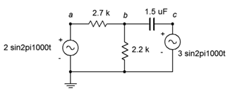
Figure \(\PageIndex{1}\)
2. For the circuit shown in Figure \(\PageIndex{1}\), use superposition to find the current through the capacitor.
3. Use superposition to find the current through the 82 \(\Omega\) resistor. For the circuit shown in Figure \(\PageIndex{2}\).
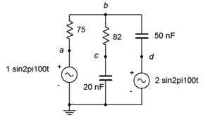
Figure \(\PageIndex{2}\)
4. Use superposition to find \(v_b\) and \(v_{cd}\) for the circuit shown in Figure \(\PageIndex{2}\).
5. In the circuit of Figure \(\PageIndex{3}\), use superposition to find \(v_b\). Source one is one volt peak and source two is two volts peak.
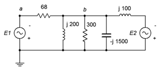
Figure \(\PageIndex{3}\)
6. In the circuit of Figure \(\PageIndex{3}\), use superposition to find the currents through the two inductors. Source one is two volts peak and source two is three volts peak.
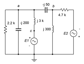
Figure \(\PageIndex{4}\)
7. Use superposition to find the current through the 2.2 k\(\Omega\) resistor for the circuit of Figure \(\PageIndex{4}\). \(E1 = 1 \angle 0^{\circ}\) and \(E2 = 10 \angle 90^{\circ}\).
8. Use superposition to find \(v_{ab}\) for In the circuit of Figure \(\PageIndex{4}\). \(E1 = 1 \angle 0^{\circ}\) and \(E2 = 2 \angle 45^{\circ}\).
9. In the circuit of Figure \(\PageIndex{5}\), use superposition to find \(v_b\) and \(v_{cd}\). The sources are in phase.
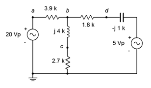
Figure \(\PageIndex{5}\)
10. In the circuit of Figure \(\PageIndex{5}\), use superposition to find the current through the capacitor. The sources are in phase.
11. Use superposition to find the two source currents for In the circuit of Figure \(\PageIndex{6}\). Source one is 100 mV peak and source two is 500 mV peak (in phase).
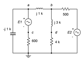
Figure \(\PageIndex{6}\)
12. Use superposition to find \(v_{cd}\) for the circuit of Figure \(\PageIndex{6}\). Source one is 100 mV peak and source two is 1 V peak (in phase).
13. In the circuit of Figure \(\PageIndex{7}\), use superposition to find \(v_{ab}\).
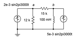
Figure \(\PageIndex{7}\)
14. In the circuit of Figure \(\PageIndex{7}\), use superposition to find the current through the 15 k\(\Omega\) resistor.
15. In the circuit of Figure \(\PageIndex{8}\), use superposition to find \(v_{ab}\).
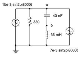
Figure \(\PageIndex{8}\)
16. In the circuit of Figure \(\PageIndex{8}\), use superposition to find the current flowing through the resistor.
17. For the circuit of Figure \(\PageIndex{9}\), use superposition to find \(v_a\) and \(v_b\). The sources are in phase.
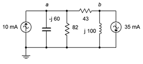
Figure \(\PageIndex{9}\)
18. For the circuit of Figure \(\PageIndex{9}\), use superposition to find the currents through the inductor and capacitor. The sources are in phase.
19. Use superposition in the circuit of Figure \(\PageIndex{10}\) to find the currents through the inductor and capacitor. \(I1 = 1 \angle 45^{\circ}\) and \(I2 = 2 \angle 45^{\circ}\).
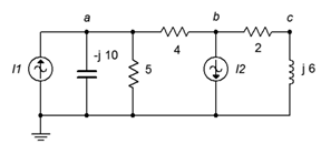
Figure \(\PageIndex{10}\)
20. Use superposition in the circuit of Figure \(\PageIndex{10}\) to find \(v_{ab}\) and \(v_{bc}\). \(I1 = 1 \angle 0^{\circ}\) and \(I2 = 2 \angle 90^{\circ}\).
21. In the circuit of Figure \(\PageIndex{11}\), Use superposition to find \(v_{bc}\). \(I1 = 10 \angle 0^{\circ}\) and \(I2 = 6 \angle 0^{\circ}\).
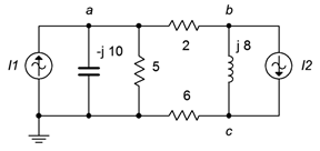
Figure \(\PageIndex{11}\)
22. In the circuit of Figure \(\PageIndex{11}\), Use superposition to find the current flowing through the 2 \(\Omega\) resistor. \(I1 = 4 \angle 120^{\circ}\) and \(I2 = 6 \angle 0^{\circ}\).
23. Use superposition to determine the current of source \(E\) in the circuit of Figure \(\PageIndex{12}\). \(E = 40 \angle 180^{\circ}\) and \(I = 20E−3 \angle 0^{\circ}\).
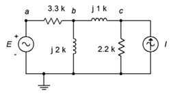
Figure \(\PageIndex{12}\)
24. Use superposition to determine \(v_{ac}\) in the circuit of Figure \(\PageIndex{12}\). \(E = 28 \angle 0^{\circ}\) and \(I = 8E−3 \angle −180^{\circ}\).
25. Use superposition to determine vb in the circuit of Figure \(\PageIndex{13}\). \(I = 3E−3 \angle 0^{\circ}\) and \(E = 9 \angle 0^{\circ}\).
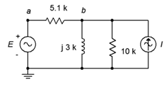
Figure \(\PageIndex{13}\)
26. Use superposition to determine the inductor current in the circuit of Figure \(\PageIndex{13}\). \(I = 4E−3 \angle 0^{\circ}\) and \(E = 18 \angle −45^{\circ}\).
27. For the circuit of Figure \(\PageIndex{14}\), use superposition to determine the inductor current. \(I = 100E−3 \angle 0^{\circ}\) and \(E = 26 \angle 0^{\circ}\).
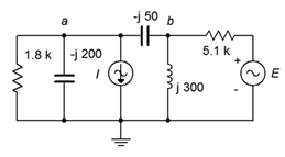
Figure \(\PageIndex{14}\)
28. For the circuit of Figure \(\PageIndex{14}\), use superposition to determine \(v_{ab}\). \(I = 50E−3 \angle 0^{\circ}\) and \(E = 18 \angle 90^{\circ}\).
29. Use superposition to determine \(v_{ab}\) in the circuit of Figure \(\PageIndex{15}\). \(I = 10E−3 \angle 0^{\circ}\) and \(E = 12 \angle 0^{\circ}\).
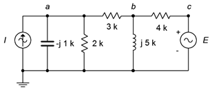
Figure \(\PageIndex{15}\)
30. Use superposition to determine the capacitor current in the circuit of Figure \(\PageIndex{15}\). \(I = 5E−3 \angle 0^{\circ}\) and \(E = 18 \angle 120^{\circ}\).
31. For the circuit of Figure \(\PageIndex{16}\), determine the Thévenin equivalent that drives the 20 nF capacitor.
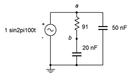
Figure \(\PageIndex{16}\)
32. Given the circuit of Figure \(\PageIndex{16}\), determine the Norton equivalent that drives the 20 nF capacitor.
33. For the circuit of Figure \(\PageIndex{17}\), determine the Thévenin and Norton equivalents that drive the 600 \(\Omega\) resistor if the source \(E = 12 \angle 0^{\circ}\).
34. Given the circuit of Figure \(\PageIndex{17}\), determine the Thévenin equivalent that drives the \(j1\) k\(\Omega\) inductive reactance if \(E = 9 \angle 0^{\circ}\).
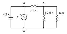
Figure \(\PageIndex{17}\)
35. Given the circuit of Figure \(\PageIndex{17}\), determine the Norton equivalent that drives the \(j2.5\) k\(\Omega\) inductive reactance if \(E = 24 \angle 45^{\circ}\).
36. Use Thévenin's theorem to find \(v_b\) in the circuit of Figure \(\PageIndex{17}\) if \(E = 18 \angle 0^{\circ}\).
37. Use Thévenin's theorem to find \(v_b\) in the circuit of Figure \(\PageIndex{18}\).
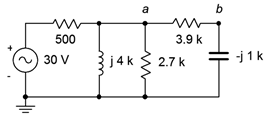
Figure \(\PageIndex{18}\)
38. Determine the Thévenin equivalent that drives the \(3.9 k\Omega + j1 k\Omega\) combo in the circuit of Figure \(\PageIndex{18}\). Does this combo's impedance achieve maximum load power? If not, what combo will achieve maximum power and what is the resulting power?
39. Determine the Norton equivalent that drives the 500 \(\Omega\) resistor in the circuit of Figure \(\PageIndex{18}\). Determine the value of component(s) that when placed in series with the 500 \(\Omega\) resistor will achieve maximum load power (i.e., for the combo as the load).
40. For the circuit of Figure \(\PageIndex{19}\), determine the Thévenin and Norton equivalents that drive the combo of \(36 \Omega + j100 \Omega\). Does this combo achieve maximum load power? If not, what combo will achieve maximum power and what is the resulting power?
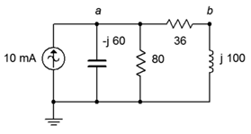
Figure \(\PageIndex{19}\)
41. For the circuit of Figure \(\PageIndex{20}\), determine the Thévenin and Norton equivalents that drive the combo of 300 \(\Omega\) in parallel with \(−j1500\) \(\Omega\). Does this combo achieve maximum load power? If not, what combo will achieve maximum power and what is the resulting power? \(E = 120 \angle 0^{\circ}\).
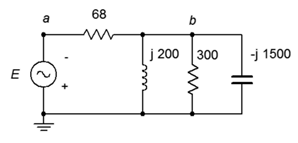
Figure \(\PageIndex{20}\)
42. For the circuit of Figure \(\PageIndex{21}\), determine the Thévenin and Norton equivalents that drive the combo of 4.7 k\(\Omega\) in parallel with \(j300\) \(\Omega\). Does this combo achieve maximum load power? If not, what combo will achieve maximum power and what is the resulting power? \(I = 200E−3 \angle 0^{\circ}\).
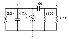
Figure \(\PageIndex{21}\)
43. Determine the equivalent Y (T) network for the circuit of Figure \(\PageIndex{22}\). \(R_1 = R_2 = R_3 = 10 k\Omega\) and \(X_{L1} = X_{L2} = X_{L3} = j10 k\Omega\).
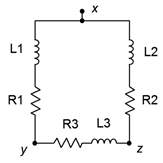
Figure \(\PageIndex{22}\)
44. Determine the equivalent Y (T) network for the circuit of Figure \(\PageIndex{23}\).
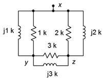
Figure \(\PageIndex{23}\)
45. Determine the equivalent Y (T) network for the circuit of Figure \(\PageIndex{24}\). \(R_1 = R_2 = R_3 = 4 k\Omega\) and \(X_{C1} = X_{C2} = X_{C3} = −j3 k\Omega\).
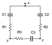
Figure \(\PageIndex{24}\)
46. Determine the equivalent Y (T) network for the circuit of Figure \(\PageIndex{25}\).
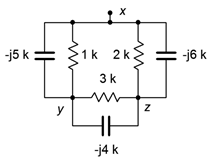
Figure \(\PageIndex{25}\)
47. Determine the equivalent delta (pi) network for the circuit of Figure \(\PageIndex{26}\).
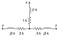
Figure \(\PageIndex{26}\)
48. Determine the equivalent delta (pi) network for the circuit of Figure \(\PageIndex{27}\).
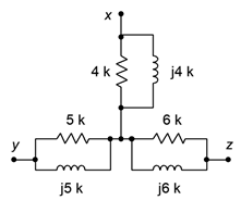
Figure \(\PageIndex{27}\)
49. Determine the equivalent delta (pi) network for the circuit of Figure \(\PageIndex{28}\).
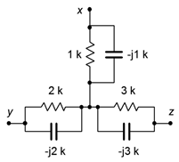
Figure \(\PageIndex{28}\)
50. Determine the equivalent delta (pi) network for the circuit of Figure \(\PageIndex{29}\).
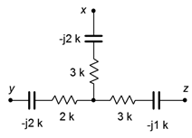
Figure \(\PageIndex{29}\)
51. Find voltage \(v_{bc}\) in the circuit of Figure \(\PageIndex{30}\) through the use of one or more delta-Y conversions. \(E = 10 \angle 0^{\circ}\), \(R_1 = 1 k\Omega\), \(R_2 = 2 k\Omega\), \(R_3 = 3 k\Omega\), \(X_C = −j4 k\Omega\) and \(X_L = j8 k\Omega\).
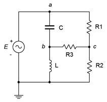
Figure \(\PageIndex{30}\)
52. Find voltage \(v_{bc}\) in the circuit of Figure \(\PageIndex{31}\) through the use of one or more delta-Y conversions. \(E = 20 \angle 0^{\circ}\), \(R_1 = 1 k\Omega\), \(R_2 = 8 k\Omega\), \(R_3 = 3 k\Omega\), \(X_C = −j4 k\Omega\) and \(X_L = j2 k\Omega\).
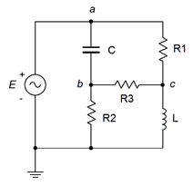
Figure \(\PageIndex{31}\)
Design
53. Design an equivalent current source for Figure \(\PageIndex{32}\). \(E = 12 \angle 90^{\circ}\), \(R = 1 k\Omega\) and \(X_C = − j200 \Omega\). The source frequency is 10 kHz.
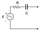
Figure \(\PageIndex{32}\)
54. Design an equivalent current source for Figure \(\PageIndex{32}\) if \(E = 10 \angle 0^{\circ}\), \(R = 2.2 k\Omega\) and \(C\) = 100 nF. The source frequency is 1 kHz.
55. Design an equivalent current source for Figure \(\PageIndex{33}\) if \(E = 1 \angle 0^{\circ}\), \(R\) = 600 \(\Omega\) and \(L\) = 2 mH. The source frequency is 20 kHz.
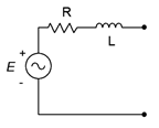
Figure \(\PageIndex{33}\)
56. Design an equivalent current source for Figure \(\PageIndex{33}\). \(E = 2 \angle 90^{\circ}\), \(R\) = 10 k\(\Omega\) and \(X_L = j900 \Omega\).
57. Design an equivalent voltage source for Figure \(\PageIndex{34}\). \(I = 300E−3 \angle 0^{\circ}\), \(R = 4.3 k\Omega\) and \(X_C = −j5 k\Omega\).
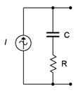
Figure \(\PageIndex{34}\)
58. Design an equivalent voltage source for Figure \(\PageIndex{34}\) if \(I = 100E−3 \angle 120^{\circ}\), \(R\) = 75 \(\Omega\) and \(L\) = 1 mH. The source frequency is 10 kHz.
59. Design an equivalent voltage source for Figure \(\PageIndex{35}\) if \(I = 10E−3 \angle 0^{\circ}\), \(R\) = 9.1 k\(\Omega\) and \(L\) = 5 mH. The source frequency is 100 kHz.
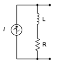
Figure \(\PageIndex{35}\)
60. Design an equivalent voltage source for Figure \(\PageIndex{35}\) if \(I = 50E−3 \angle 0^{\circ}\), \(R\) = 560 \(\Omega\) and \(X_L = j350 \Omega\).
61. Reconfigure the circuit of Figure \(\PageIndex{36}\) so that it uses only voltage sources. Express all new component and source values in terms of the original labels.
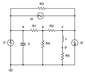
Figure \(\PageIndex{36}\)
62. Reconfigure the circuit of Figure \(\PageIndex{37}\) so that it uses only current sources. Express all new component and source values in terms of the original labels.
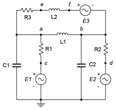
Figure \(\PageIndex{37}\)
63. Redesign the circuit of Figure \(\PageIndex{1}\) so that it uses only current sources and produces the same node voltages as the original circuit.
64. Consider the 600 \(\Omega\) resistor to be the load in Figure \(\PageIndex{17}\). Determine a new value for the load in order to achieve maximum load power. Also determine the maximum load power.
65. Using Thévenin's theorem with the circuit of Figure \(\PageIndex{18}\), determine a new value of capacitive reactance such that it cancels the Thévenin reactance.
66. Using Norton's theorem with the circuit of Figure \(\PageIndex{19}\), determine a new value of inductive reactance such that the inductor current is 1 mA in magnitude.
Challenge
67. Redesign the circuit of problem 7 (Figure \(\PageIndex{4}\)) so that it uses only current sources and produces the same node voltages as the original circuit.
68. In the circuit of Figure \(\PageIndex{38}\), use any method or combination of methods to determine \(v_{ab}\). \(I1 = 0.05 \angle 0^{\circ}\), \(I2 = 0.1 \angle 0^{\circ}\) and \(I3 = 0.2 \angle 90^{\circ}\).
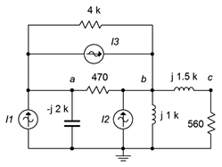
Figure \(\PageIndex{38}\)
69. In the circuit of Figure \(\PageIndex{39}\), use any method or combination of methods to determine \(v_{ab}\). \(E1 = 5 \angle 0^{\circ}\), \(E2 = 10 \angle 90^{\circ}\) and \(E3 = 15 \angle 0^{\circ}\).
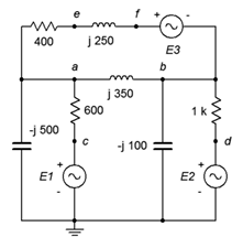
Figure \(\PageIndex{39}\)
70. In the circuit of Figure \(\PageIndex{39}\), use any method or combination of methods to determine \(v_{ce}\). \(E1 = 15 \angle 0^{\circ}\), \(E2 = 30 \angle 90^{\circ}\) and \(E3 = 45 \angle 0^{\circ}\).
71. Use any method or combination of methods in the circuit of Figure \(\PageIndex{40}\) to determine \(v_{ad}\). \(E1 = 90 \angle 0^{\circ}\), \(E2 = 120 \angle 0^{\circ}\) and \(I = 400E−3 \angle 180^{\circ}\).
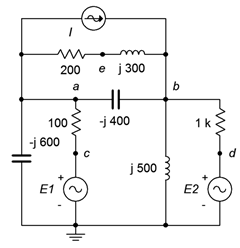
Figure \(\PageIndex{40}\)
72. Consider the \(2.7 k\Omega + j4 k\Omega\) combo to be the load in Figure \(\PageIndex{5}\). Determine if this value achieves maximum load power. If not, determine a new value for the load in order to achieve maximum load power. Also determine the maximum load power.
73. In the circuit of Figure \(\PageIndex{41}\), assume the source \(E\) is 120 volts RMS at 60 Hz. Determine the value for the load, \(Z\), that will produce maximum load power. Express \(Z\) in terms of a resistor and either an inductor or capacitor. Further, specify both the series and parallel equivalents for the load.
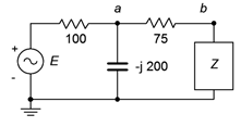
Figure \(\PageIndex{41}\)
74. Convert the circuit of Figure \(\PageIndex{42}\) into the equivalent delta configuration.
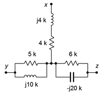
Figure \(\PageIndex{42}\)
75. Find the Thévenin equivalent looking into nodes \(a\) and \(b\) for the circuit of Figure \(\PageIndex{43}\). \(I = 4 \angle 0^{\circ}\).
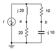
Figure \(\PageIndex{43}\)
76. Find voltage \(v_{bc}\) in the circuit of Figure \(\PageIndex{44}\) through the use of one or more delta-Y conversions. \(E = 100 \angle 0^{\circ}\), \(R_1 = R2 = 2 k\Omega\), \(R_3 = 3 k\Omega\), \(R_4 = 10 k\Omega\), \(R_5 = 5 k\Omega\), \(X_{C1} = X_{C2} = −j2 k\Omega\).
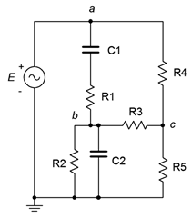
Figure \(\PageIndex{44}\)
77. Given the circuit of Figure \(\PageIndex{45}\), determine an equivalent circuit using a single voltage source. \(E1 = 100 \angle 0^{\circ}\), \(E2 = 60 \angle 180^{\circ}\), \(E3 = 40 \angle 90^{\circ}\), \(E4 = 75 \angle 0^{\circ}\).
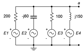
Figure \(\PageIndex{45}\)
78. As mentioned earlier, it is possible that certain AC Y and delta networks cannot be converted. Consider the circuit of Figure \(\PageIndex{46}\). Can this circuit be converted with a practical outcome? Why/why not?
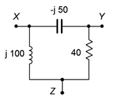
Figure \(\PageIndex{46}\)
Simulation
79. Verify the voltage computed for problem 1 by running a transient analysis.
80. Verify the voltage computed for problem 4 by running a transient analysis.
81. Using multiple transient analysis simulations, compare the original circuit of problem 54 to its converted equivalent. Do this by connecting various components to the output terminals, trying several different impedance values and checking to see if the two circuits always produce the same voltage across this impedance.
82. Using multiple transient analysis simulations, compare the original circuit of problem 59 to its converted equivalent. Do this by connecting various components to the output terminals, trying several different impedance values and checking to see if the two circuits always produce the same voltage across this impedance.
83. Run a transient analysis to verify the design of problem 70.
84. Run a transient analysis to verify the design of problem 71.