
13.4: Power Systems
- Page ID
- 52980

\( \newcommand{\vecs}[1]{\overset { \scriptstyle \rightharpoonup} {\mathbf{#1}} } \)
\( \newcommand{\vecd}[1]{\overset{-\!-\!\rightharpoonup}{\vphantom{a}\smash {#1}}} \)
\( \newcommand{\dsum}{\displaystyle\sum\limits} \)
\( \newcommand{\dint}{\displaystyle\int\limits} \)
\( \newcommand{\dlim}{\displaystyle\lim\limits} \)
\( \newcommand{\id}{\mathrm{id}}\) \( \newcommand{\Span}{\mathrm{span}}\)
( \newcommand{\kernel}{\mathrm{null}\,}\) \( \newcommand{\range}{\mathrm{range}\,}\)
\( \newcommand{\RealPart}{\mathrm{Re}}\) \( \newcommand{\ImaginaryPart}{\mathrm{Im}}\)
\( \newcommand{\Argument}{\mathrm{Arg}}\) \( \newcommand{\norm}[1]{\| #1 \|}\)
\( \newcommand{\inner}[2]{\langle #1, #2 \rangle}\)
\( \newcommand{\Span}{\mathrm{span}}\)
\( \newcommand{\id}{\mathrm{id}}\)
\( \newcommand{\Span}{\mathrm{span}}\)
\( \newcommand{\kernel}{\mathrm{null}\,}\)
\( \newcommand{\range}{\mathrm{range}\,}\)
\( \newcommand{\RealPart}{\mathrm{Re}}\)
\( \newcommand{\ImaginaryPart}{\mathrm{Im}}\)
\( \newcommand{\Argument}{\mathrm{Arg}}\)
\( \newcommand{\norm}[1]{\| #1 \|}\)
\( \newcommand{\inner}[2]{\langle #1, #2 \rangle}\)
\( \newcommand{\Span}{\mathrm{span}}\) \( \newcommand{\AA}{\unicode[.8,0]{x212B}}\)
\( \newcommand{\vectorA}[1]{\vec{#1}} % arrow\)
\( \newcommand{\vectorAt}[1]{\vec{\text{#1}}} % arrow\)
\( \newcommand{\vectorB}[1]{\overset { \scriptstyle \rightharpoonup} {\mathbf{#1}} } \)
\( \newcommand{\vectorC}[1]{\textbf{#1}} \)
\( \newcommand{\vectorD}[1]{\overrightarrow{#1}} \)
\( \newcommand{\vectorDt}[1]{\overrightarrow{\text{#1}}} \)
\( \newcommand{\vectE}[1]{\overset{-\!-\!\rightharpoonup}{\vphantom{a}\smash{\mathbf {#1}}}} \)
\( \newcommand{\vecs}[1]{\overset { \scriptstyle \rightharpoonup} {\mathbf{#1}} } \)
\(\newcommand{\longvect}{\overrightarrow}\)
\( \newcommand{\vecd}[1]{\overset{-\!-\!\rightharpoonup}{\vphantom{a}\smash {#1}}} \)
\(\newcommand{\avec}{\mathbf a}\) \(\newcommand{\bvec}{\mathbf b}\) \(\newcommand{\cvec}{\mathbf c}\) \(\newcommand{\dvec}{\mathbf d}\) \(\newcommand{\dtil}{\widetilde{\mathbf d}}\) \(\newcommand{\evec}{\mathbf e}\) \(\newcommand{\fvec}{\mathbf f}\) \(\newcommand{\nvec}{\mathbf n}\) \(\newcommand{\pvec}{\mathbf p}\) \(\newcommand{\qvec}{\mathbf q}\) \(\newcommand{\svec}{\mathbf s}\) \(\newcommand{\tvec}{\mathbf t}\) \(\newcommand{\uvec}{\mathbf u}\) \(\newcommand{\vvec}{\mathbf v}\) \(\newcommand{\wvec}{\mathbf w}\) \(\newcommand{\xvec}{\mathbf x}\) \(\newcommand{\yvec}{\mathbf y}\) \(\newcommand{\zvec}{\mathbf z}\) \(\newcommand{\rvec}{\mathbf r}\) \(\newcommand{\mvec}{\mathbf m}\) \(\newcommand{\zerovec}{\mathbf 0}\) \(\newcommand{\onevec}{\mathbf 1}\) \(\newcommand{\real}{\mathbb R}\) \(\newcommand{\twovec}[2]{\left[\begin{array}{r}#1 \\ #2 \end{array}\right]}\) \(\newcommand{\ctwovec}[2]{\left[\begin{array}{c}#1 \\ #2 \end{array}\right]}\) \(\newcommand{\threevec}[3]{\left[\begin{array}{r}#1 \\ #2 \\ #3 \end{array}\right]}\) \(\newcommand{\cthreevec}[3]{\left[\begin{array}{c}#1 \\ #2 \\ #3 \end{array}\right]}\) \(\newcommand{\fourvec}[4]{\left[\begin{array}{r}#1 \\ #2 \\ #3 \\ #4 \end{array}\right]}\) \(\newcommand{\cfourvec}[4]{\left[\begin{array}{c}#1 \\ #2 \\ #3 \\ #4 \end{array}\right]}\) \(\newcommand{\fivevec}[5]{\left[\begin{array}{r}#1 \\ #2 \\ #3 \\ #4 \\ #5 \\ \end{array}\right]}\) \(\newcommand{\cfivevec}[5]{\left[\begin{array}{c}#1 \\ #2 \\ #3 \\ #4 \\ #5 \\ \end{array}\right]}\) \(\newcommand{\mattwo}[4]{\left[\begin{array}{rr}#1 \amp #2 \\ #3 \amp #4 \\ \end{array}\right]}\) \(\newcommand{\laspan}[1]{\text{Span}\{#1\}}\) \(\newcommand{\bcal}{\cal B}\) \(\newcommand{\ccal}{\cal C}\) \(\newcommand{\scal}{\cal S}\) \(\newcommand{\wcal}{\cal W}\) \(\newcommand{\ecal}{\cal E}\) \(\newcommand{\coords}[2]{\left\{#1\right\}_{#2}}\) \(\newcommand{\gray}[1]{\color{gray}{#1}}\) \(\newcommand{\lgray}[1]{\color{lightgray}{#1}}\) \(\newcommand{\rank}{\operatorname{rank}}\) \(\newcommand{\row}{\text{Row}}\) \(\newcommand{\col}{\text{Col}}\) \(\renewcommand{\row}{\text{Row}}\) \(\newcommand{\nul}{\text{Nul}}\) \(\newcommand{\var}{\text{Var}}\) \(\newcommand{\corr}{\text{corr}}\) \(\newcommand{\len}[1]{\left|#1\right|}\) \(\newcommand{\bbar}{\overline{\bvec}}\) \(\newcommand{\bhat}{\widehat{\bvec}}\) \(\newcommand{\bperp}{\bvec^\perp}\) \(\newcommand{\xhat}{\widehat{\xvec}}\) \(\newcommand{\vhat}{\widehat{\vvec}}\) \(\newcommand{\uhat}{\widehat{\uvec}}\) \(\newcommand{\what}{\widehat{\wvec}}\) \(\newcommand{\Sighat}{\widehat{\Sigma}}\) \(\newcommand{\lt}{<}\) \(\newcommand{\gt}{>}\) \(\newcommand{\amp}{&}\) \(\definecolor{fillinmathshade}{gray}{0.9}\)In this section we shall change our focus and consider power systems at a more functional or abstract level rather than at the component level. Specifically, we would like to consider common loads such as motors, heating elements, lighting devices and the like, and how to analyze a system consisting of a variety of different loads. For the most part, we shall stick with the basic scheme of multiple loads being supplied by a common and ideally constant voltage source with each load configured in parallel with the others. Systems do not have to be configured this way but it is typical of residential and commercial applications.
Typical Loads
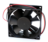
Three common loads are heating elements, lighting devices and motors or compressors. The first two are fairly obvious, but the the latter are also quite common, although often hidden from view inside devices such as refrigerators, air conditioners and heat pumps. We can classify loads in terms of their typical impedance. Devices such as baseboard electrical heating units, toasters, coffee makers and electric ovens are classified as resistive heating devices. The load they present is easily approximated as a simple resistance. The same is true for incandescent lights, however, there can be a very large change in resistance between the on and off states of incandescent lights. Motors, and other devices integrating motors such as compressors, present an inductive impedance. This is due to the large coils of wire, or windings, inside the motor. Any motorized electrical device falls into this category, such as a washing machine, drill press or the fan of Figure \(\PageIndex{1}\).
Purely capacitive loads are not nearly as common but some everyday devices exhibit highly complex impedances that can vary widely in both amplitude and angle. A standard moving coil dynamic loudspeaker falls into this category. While you would never plug a loudspeaker directly into an AC power system1, the amplifier that drives it must be designed to meet the challenges of an impedance whose magnitude can change by a factor of ten across the audible range of frequencies. To complicate matters, while the phase typically is inductive, at some frequencies it can be purely resistive or even capacitive.
Efficiency
Efficiency is defined as usable power output divided by applied power input and is denoted by the Greek letter eta, \eta . Normally it is expressed as a percentage and it can never be over 100%.
\[\eta = \frac{P_{output}}{P_{input}} \label{7.12} \]
Some loads, such as typical heating elements, can be thought of as being 100% efficient, meaning that all of the electrical input is turned into useful output (in this case that's heat, although there are more effective ways of using that electrical input to generate heat, such as a heat pump2). In contrast, incandescent light bulbs turn very little of their input into the desired quantity (light) and thus suffer from low efficiency. Just a few percent of the electrical energy fed into an incandescent bulb turns into light while the vast majority turns into heat. From that perspective, incandescent lights are more efficient at producing heat than light. LED lighting, on the other hand, is perhaps an order of magnitude more efficient than incandescent lighting, meaning that we can get the same light output for a much smaller electrical power input while simultaneously producing less heat.
Motors lose power in the form of mechanical losses (e.g., friction) and electrical losses (e.g., resistance of windings). Motors are rated in terms of their output power, not the power they draw from the source. For example, a motor with a 1 HP rating might be said to generate 1 HP (approximately 745.7 W) at the shaft. If the motor is 90% efficient, the electrical draw would be 745.7 W/0.9 or 829 W. This situation is further complicated by the phase angle (i.e., power factor) of the motor due to reactive elements, as noted in the previous sections. Compared to motors, home loudspeakers are particularly inefficient, typically converting only about 1% of the electrical input into usable acoustic output.
Example \(\PageIndex{1}\)
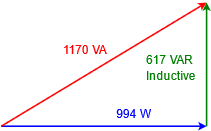
A certain 120 VAC RMS 60 Hz 1.2 HP motor has an efficiency of 90% and a lagging power factor of 0.85. Determine the apparent power and the current drawn from the system. Also draw the power triangle. 1 HP \(\approx\) 745.7 watts.
The motor output is 1.2 horsepower which is equivalent to:
\[P_{watts} \approx 1.2 HP\times 745.7W/HP \nonumber \]
\[P_{watts} \approx 895W \nonumber \]
The input required to achieve this is computed with Equation \ref{7.12}.
\[P_{input} = \frac{P_{output}}{\eta} \nonumber \]
\[P_{input} = \frac{895W}{0.9} \nonumber \]
\[P_{input} = 994 W \nonumber \]
From Equations 7.3.7 and 7.3.8, the remaining powers are:
\[S = \frac{P}{PF} \nonumber \]
\[S = \frac{994W}{0.85} \nonumber \]
\[S = 1170VA \nonumber \]
\[Q = \sqrt{S^2−P^2} \nonumber \]
\[Q = \sqrt{(1170VA)^2−(994W)^2} \nonumber \]
\[Q = 617 VAR \nonumber \]
The current is found via Equation 7.3.1, essentially power law:
\[S = v_{RMS} \times i_{RMS} \nonumber \]
\[i_{RMS} = \frac{S}{v_{RMS}} \nonumber \]
\[i_{RMS} = \frac{1170 VA}{120V} \nonumber \]
\[i_{RMS} = 9.75 A \nonumber \]
The power triangle is shown in Figure \(\PageIndex{2}\).
Example \(\PageIndex{2}\)
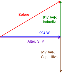
For the motor described in Example \(\PageIndex{1}\), determine an appropriate component that when placed in parallel will produce unity power factor. Draw the complete power triangle for the system and determine the new current draw.
In Example \(\PageIndex{1}\) the reactive power was determined to be 617 VAR and was inductive, so we'll need 617 VAR capacitive to compensate. The new power triangle is shown in Figure \(\PageIndex{3}\). The source voltage was stated to be 120 V. We can use a variation on power law to determine the required reactance.
\[Q = \frac{v_{RMS}^2}{X_C} \nonumber \]
\[X_C = \frac{v_{RMS}^2}{Q} \nonumber \]
\[X_C = \frac{120 V^2}{617 VAR} \nonumber \]
\[X_C =− j 23.34 \Omega \nonumber \]
Now use the capacitive reactance formula to determine the capacitance value. The line frequency was specified as 60 Hz.
\[C = \frac{1}{2\pi f X_C} \nonumber \]
\[C = \frac{1}{2\pi 60 Hz 23.34\Omega} \nonumber \]
\[C = 114\mu F \nonumber \]
After correction, the apparent power and real power are the same. Thus,
\[i_{RMS} = \frac{S}{v_{RMS}} \nonumber \]
\[i_{RMS} = \frac{994 VA}{120 V} \nonumber \]
\[i_{RMS} = 8.28A \nonumber \]
The current draw has been reduced by nearly 1.5 amps, a considerable savings. The new current is 85% of what it used to be.
Now let's consider a larger system that contains several devices.
Example \(\PageIndex{3}\)
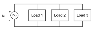
The system shown in Figure \(\PageIndex{4}\) is supplied by a 240 VAC RMS 60 Hz source. Load 1 is 1000 watts of resistive heating elements. Load 2 is a 3 HP motor with an efficiency of 92% and a lagging power factor of 0.75. Load 3 is a capacitor bank equivalent to 75 \(\mu\) F. Draw the system power triangle and determine whether or not load 3 is appropriate to bring the system power factor to unity.
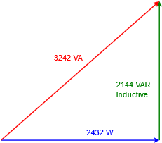
First, determine the power triangle for the motor. Then we can add the other loads to it to create a system power triangle. The motor output is 3 HP which is equivalent to:
\[P_{watts} \approx 3 HP\times 745.7W/HP \nonumber \]
\[P_{watts} \approx 2237W \nonumber \]
The required input power is.
\[P_{input} = \frac{P_{output}}{\eta} \nonumber \]
\[P_{input} = \frac{2237W}{0.92} \nonumber \]
\[P_{input} = 2432W \nonumber \]
The computations for apparent and reactive power follow.
\[S = \frac{P}{PF} \nonumber \]
\[S = \frac{2432W}{0.75} \nonumber \]
\[S = 3242VA \nonumber \]
\[Q = \sqrt{S^2−P^2} \nonumber \]
\[Q = \sqrt{(3242VA)^2−(2432W)^2} \nonumber \]
\[Q = 2144 \text{ VAR, inductive} \nonumber \]
The power triangle for the motor is shown in Figure \(\PageIndex{5}\).
Now for the capacitor. First, we need to determine the reactance, then we can use the \(v^2 /Z\) form of power law to determine \(Q\).
\[X_C = \frac{1}{2\pi f C} \nonumber \]
\[X_C = \frac{1}{2 \pi 60 Hz 75\mu F} \nonumber \]
\[X_C =− j 35.37\Omega \nonumber \]
\[Q = \frac{v^2}{X} \nonumber \]
\[Q = \frac{(240 V)^2}{35.37\Omega} \nonumber \]
\[Q = 1629 \text{ VAR, capacitive} \nonumber \]
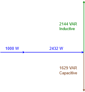
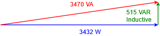
There are no other reactive elements in the system to consider. We have 515 fewer capacitive VAR than inductive VAR, so the correction will not be ideal. We would need to increase the total capacitance by about 24 \mu F to achieve a power factor of unity. The system power diagram with all of the individual parts is shown in Figure \(\PageIndex{6}\). This is then simplified to the final system power triangle as shown in Figure \(\PageIndex{7}\). The system \(PF\) is 0.989 lagging.
References
1That is, unless you enjoy hearing a short-lived blast of sound which is followed by a burst of flames. Plugging a nominal 8 \(\Omega\) loudspeaker into a 120 VAC outlet would generate 1800 watts of power, well beyond the design limits of any common loudspeaker.
2A heat pump moves heat from one place to another. In a properly designed system it takes less energy to move heat than it takes to generate it, and thus it's much more effective than simple resistive heating when it comes to warming the interior of a building.