
9.3: Relationship Types
- Page ID
- 92187
\( \newcommand{\vecs}[1]{\overset { \scriptstyle \rightharpoonup} {\mathbf{#1}} } \)
\( \newcommand{\vecd}[1]{\overset{-\!-\!\rightharpoonup}{\vphantom{a}\smash {#1}}} \)
\( \newcommand{\dsum}{\displaystyle\sum\limits} \)
\( \newcommand{\dint}{\displaystyle\int\limits} \)
\( \newcommand{\dlim}{\displaystyle\lim\limits} \)
\( \newcommand{\id}{\mathrm{id}}\) \( \newcommand{\Span}{\mathrm{span}}\)
( \newcommand{\kernel}{\mathrm{null}\,}\) \( \newcommand{\range}{\mathrm{range}\,}\)
\( \newcommand{\RealPart}{\mathrm{Re}}\) \( \newcommand{\ImaginaryPart}{\mathrm{Im}}\)
\( \newcommand{\Argument}{\mathrm{Arg}}\) \( \newcommand{\norm}[1]{\| #1 \|}\)
\( \newcommand{\inner}[2]{\langle #1, #2 \rangle}\)
\( \newcommand{\Span}{\mathrm{span}}\)
\( \newcommand{\id}{\mathrm{id}}\)
\( \newcommand{\Span}{\mathrm{span}}\)
\( \newcommand{\kernel}{\mathrm{null}\,}\)
\( \newcommand{\range}{\mathrm{range}\,}\)
\( \newcommand{\RealPart}{\mathrm{Re}}\)
\( \newcommand{\ImaginaryPart}{\mathrm{Im}}\)
\( \newcommand{\Argument}{\mathrm{Arg}}\)
\( \newcommand{\norm}[1]{\| #1 \|}\)
\( \newcommand{\inner}[2]{\langle #1, #2 \rangle}\)
\( \newcommand{\Span}{\mathrm{span}}\) \( \newcommand{\AA}{\unicode[.8,0]{x212B}}\)
\( \newcommand{\vectorA}[1]{\vec{#1}} % arrow\)
\( \newcommand{\vectorAt}[1]{\vec{\text{#1}}} % arrow\)
\( \newcommand{\vectorB}[1]{\overset { \scriptstyle \rightharpoonup} {\mathbf{#1}} } \)
\( \newcommand{\vectorC}[1]{\textbf{#1}} \)
\( \newcommand{\vectorD}[1]{\overrightarrow{#1}} \)
\( \newcommand{\vectorDt}[1]{\overrightarrow{\text{#1}}} \)
\( \newcommand{\vectE}[1]{\overset{-\!-\!\rightharpoonup}{\vphantom{a}\smash{\mathbf {#1}}}} \)
\( \newcommand{\vecs}[1]{\overset { \scriptstyle \rightharpoonup} {\mathbf{#1}} } \)
\(\newcommand{\longvect}{\overrightarrow}\)
\( \newcommand{\vecd}[1]{\overset{-\!-\!\rightharpoonup}{\vphantom{a}\smash {#1}}} \)
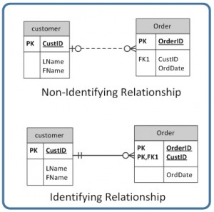
\(\newcommand{\avec}{\mathbf a}\) \(\newcommand{\bvec}{\mathbf b}\) \(\newcommand{\cvec}{\mathbf c}\) \(\newcommand{\dvec}{\mathbf d}\) \(\newcommand{\dtil}{\widetilde{\mathbf d}}\) \(\newcommand{\evec}{\mathbf e}\) \(\newcommand{\fvec}{\mathbf f}\) \(\newcommand{\nvec}{\mathbf n}\) \(\newcommand{\pvec}{\mathbf p}\) \(\newcommand{\qvec}{\mathbf q}\) \(\newcommand{\svec}{\mathbf s}\) \(\newcommand{\tvec}{\mathbf t}\) \(\newcommand{\uvec}{\mathbf u}\) \(\newcommand{\vvec}{\mathbf v}\) \(\newcommand{\wvec}{\mathbf w}\) \(\newcommand{\xvec}{\mathbf x}\) \(\newcommand{\yvec}{\mathbf y}\) \(\newcommand{\zvec}{\mathbf z}\) \(\newcommand{\rvec}{\mathbf r}\) \(\newcommand{\mvec}{\mathbf m}\) \(\newcommand{\zerovec}{\mathbf 0}\) \(\newcommand{\onevec}{\mathbf 1}\) \(\newcommand{\real}{\mathbb R}\) \(\newcommand{\twovec}[2]{\left[\begin{array}{r}#1 \\ #2 \end{array}\right]}\) \(\newcommand{\ctwovec}[2]{\left[\begin{array}{c}#1 \\ #2 \end{array}\right]}\) \(\newcommand{\threevec}[3]{\left[\begin{array}{r}#1 \\ #2 \\ #3 \end{array}\right]}\) \(\newcommand{\cthreevec}[3]{\left[\begin{array}{c}#1 \\ #2 \\ #3 \end{array}\right]}\) \(\newcommand{\fourvec}[4]{\left[\begin{array}{r}#1 \\ #2 \\ #3 \\ #4 \end{array}\right]}\) \(\newcommand{\cfourvec}[4]{\left[\begin{array}{c}#1 \\ #2 \\ #3 \\ #4 \end{array}\right]}\) \(\newcommand{\fivevec}[5]{\left[\begin{array}{r}#1 \\ #2 \\ #3 \\ #4 \\ #5 \\ \end{array}\right]}\) \(\newcommand{\cfivevec}[5]{\left[\begin{array}{c}#1 \\ #2 \\ #3 \\ #4 \\ #5 \\ \end{array}\right]}\) \(\newcommand{\mattwo}[4]{\left[\begin{array}{rr}#1 \amp #2 \\ #3 \amp #4 \\ \end{array}\right]}\) \(\newcommand{\laspan}[1]{\text{Span}\{#1\}}\) \(\newcommand{\bcal}{\cal B}\) \(\newcommand{\ccal}{\cal C}\) \(\newcommand{\scal}{\cal S}\) \(\newcommand{\wcal}{\cal W}\) \(\newcommand{\ecal}{\cal E}\) \(\newcommand{\coords}[2]{\left\{#1\right\}_{#2}}\) \(\newcommand{\gray}[1]{\color{gray}{#1}}\) \(\newcommand{\lgray}[1]{\color{lightgray}{#1}}\) \(\newcommand{\rank}{\operatorname{rank}}\) \(\newcommand{\row}{\text{Row}}\) \(\newcommand{\col}{\text{Col}}\) \(\renewcommand{\row}{\text{Row}}\) \(\newcommand{\nul}{\text{Nul}}\) \(\newcommand{\var}{\text{Var}}\) \(\newcommand{\corr}{\text{corr}}\) \(\newcommand{\len}[1]{\left|#1\right|}\) \(\newcommand{\bbar}{\overline{\bvec}}\) \(\newcommand{\bhat}{\widehat{\bvec}}\) \(\newcommand{\bperp}{\bvec^\perp}\) \(\newcommand{\xhat}{\widehat{\xvec}}\) \(\newcommand{\vhat}{\widehat{\vvec}}\) \(\newcommand{\uhat}{\widehat{\uvec}}\) \(\newcommand{\what}{\widehat{\wvec}}\) \(\newcommand{\Sighat}{\widehat{\Sigma}}\) \(\newcommand{\lt}{<}\) \(\newcommand{\gt}{>}\) \(\newcommand{\amp}{&}\) \(\definecolor{fillinmathshade}{gray}{0.9}\)The line that connects two tables, in an ERD, indicates the relationship type between the tables: either identifying or non-identifying. An identifying relationship will have a solid line (where the PK contains the FK). A non-identifying relationship is indicated by a broken line and does not contain the FK in the PK. See the section in Chapter 8 that discusses weak and strong relationships for more explanation.
Optional relationships
In an optional relationship, the FK can be null or the parent table does not need to have a corresponding child table occurrence. The symbol, shown in Figure \(\PageIndex{2}\), illustrates one type with a zero and three prongs (indicating many) which is interpreted as zero OR many.

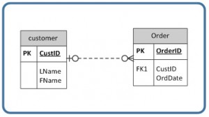
For example, if you look at the Order table on the right-hand side of Figure \(\PageIndex{3}\), you’ll notice that a customer doesn’t need to place an order to be a customer. In other words, the many side is optional.
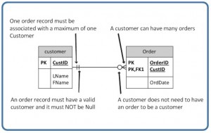
The relationship symbol in Figure \(\PageIndex{3}\) can also be read as follows:
- Left side: The order entity must contain a minimum of one related entity in the Customer table and a maximum of one related entity.
- Right side: A customer can place a minimum of zero orders or a maximum of many orders.
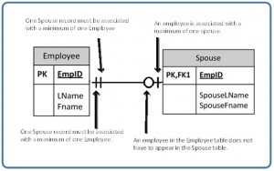
Figure \(\PageIndex{4}\) shows another type of optional relationship symbol with a zero and one, meaning zero OR one. The one side is optional.
Figure \(\PageIndex{5}\) gives an example of how a zero to one symbol might be used.
Mandatory relationships
In a mandatory relationship, one entity occurrence requires a corresponding entity occurrence. The symbol for this relationship shows one and only one as shown in Figure \(\PageIndex{6}\). The one side is mandatory.

See Figure \(\PageIndex{7}\) for an example of how the one and only one mandatory symbol is used.
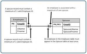
Figure \(\PageIndex{8}\) illustrates what a one to many relationship symbol looks like where the many side is mandatory.

Refer to Figure \(\PageIndex{9}\) for an example of how the one to many symbol may be used.

So far we have seen that the innermost side of a relationship symbol (on the left-side of the symbol in Figure \(\PageIndex{10}\)) can have a 0 (zero) cardinality and a connectivity of many (shown on the right-side of the symbol in Figure \(\PageIndex{10}\)), or one (not shown).

However, it cannot have a connectivity of 0 (zero), as displayed in Figure \(\PageIndex{11}\). The connectivity can only be 1.

The connectivity symbols show maximums. So if you think about it logically, if the connectivity symbol on the left side shows 0 (zero), then there would be no connection between the tables.
The way to read a relationship symbol, such as the one in Figure \(\PageIndex{12}\), is as follows.
- The CustID in the Order table must also be found in the Customer table a minimum of 0 and a maximum of 1 times.
- The 0 means that the CustID in the Order table may be null.
- The left-most 1 (right before the 0 representing connectivity) says that if there is a CustID in the Order table, it can only be in the Customer table once.
- When you see the 0 symbol for cardinality, you can assume two things: T
- the FK in the Order table allows nulls, and
- the FK is not part of the PK since PKs must not contain null values.
Key Terms
business rules: obtained from users when gathering requirements and are used to determine cardinality
cardinality: expresses the minimum and maximum number of entity occurrences associated with one occurrence of a related entity
connectivity: the relationship between two tables, e.g., one to one or one to many
constraints: the rules that force DBMSs to check that data satisfies the semantics
entity integrity: requires that every table have a primary key; neither the primary key, nor any part of it, can contain null values
identifying relationship: where the primary key contains the foreign key; indicated in an ERD by a solid line
integrity constraints: logical statements that state what data values are or are not allowed and which format is suitable for an attribute
mandatory relationship:one entity occurrence requires a corresponding entity occurrence.
non-identifying relationship: does not contain the foreign key in the primary key; indicated in an ERD by a dotted line
optional relationship: the FK can be null or the parent table does not need to have a corresponding child table occurrence
orphan record: a record whose foreign key value is not found in the corresponding entity – the entity where the primary key is located
referential integrity: requires that a foreign key must have a matching primary key or it must be null
relational database management system (RDBMS): a popular database system based on the relational model introduced by E. F. Codd of IBM’s San Jose Research Laboratory
relationship type: the type of relationship between two tables in an ERD (either identifying or non-identifying); this relationship is indicated by a line drawn between the two tables.
Exercises
Read the following description and then answer questions 1-5 at the end.
The swim club database in Figure 9.5.16 has been designed to hold information about students who are enrolled in swim classes. The following information is stored: students, enrollment, swim classes, pools where classes are held, instructors for the classes, and various levels of swim classes. Use Figure 9.5.16 to answer questions 1 to 5.
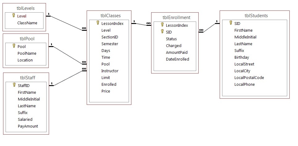
The primary keys are identified below. The following data types are defined in the SQL Server.
tblLevels
Level – Identity PK
ClassName – text 20 – nulls are not allowed
tblPool
Pool – Identity PK
PoolName – text 20 – nulls are not allowed
Location – text 30
tblStaff
StaffID – Identity PK
FirstName – text 20
MiddleInitial – text 3
LastName – text 30
Suffix – text 3
Salaried – Bit
PayAmount – money
tblClasses
LessonIndex – Identity PK
Level – Integer FK
SectionID – Integer
Semester – TinyInt
Days – text 20
Time – datetime (formatted for time)
Pool – Integer FK
Instructor – Integer FK
Limit – TinyInt
Enrolled – TinyInt
Price – money
tblEnrollment
LessonIndex – Integer FK
SID – Integer FK (LessonIndex and SID) Primary Key
Status – text 30
Charged – bit
AmountPaid – money
DateEnrolled – datetime
tblStudents
SID – Identity PK
FirstName – text 20
MiddleInitial – text 3
LastName – text 30
Suffix – text 3
Birthday – datetime
LocalStreet – text 30
LocalCity – text 20
LocalPostalCode – text 6
LocalPhone – text 10
Implement this schema in SQL Server or access (you will need to pick comparable data types). Submit a screenshot of your ERD in the database.
- Explain the relationship rules for each relationship (e.g., tblEnrollment and tblStudents: A student can enroll in many classes).
- Identify cardinality for each relationship, assuming the following rules:
- A pool may or may not ever have a class.
- The levels table must always be associated with at least one class.
- The staff table may not have ever taught a class.
- All students must be enrolled in at least one class.
- The class must have students enrolled in it.
- The class must have a valid pool.
- The class may not have an instructor assigned.
- The class must always be associated with an existing level.
- Which tables are weak and which tables are strong (covered in an earlier chapter)?
- Which of the tables are non-identifying and which are identifying?