
8.2.3: Point Absorbers
- Page ID
- 85134
\( \newcommand{\vecs}[1]{\overset { \scriptstyle \rightharpoonup} {\mathbf{#1}} } \)
\( \newcommand{\vecd}[1]{\overset{-\!-\!\rightharpoonup}{\vphantom{a}\smash {#1}}} \)
\( \newcommand{\id}{\mathrm{id}}\) \( \newcommand{\Span}{\mathrm{span}}\)
( \newcommand{\kernel}{\mathrm{null}\,}\) \( \newcommand{\range}{\mathrm{range}\,}\)
\( \newcommand{\RealPart}{\mathrm{Re}}\) \( \newcommand{\ImaginaryPart}{\mathrm{Im}}\)
\( \newcommand{\Argument}{\mathrm{Arg}}\) \( \newcommand{\norm}[1]{\| #1 \|}\)
\( \newcommand{\inner}[2]{\langle #1, #2 \rangle}\)
\( \newcommand{\Span}{\mathrm{span}}\)
\( \newcommand{\id}{\mathrm{id}}\)
\( \newcommand{\Span}{\mathrm{span}}\)
\( \newcommand{\kernel}{\mathrm{null}\,}\)
\( \newcommand{\range}{\mathrm{range}\,}\)
\( \newcommand{\RealPart}{\mathrm{Re}}\)
\( \newcommand{\ImaginaryPart}{\mathrm{Im}}\)
\( \newcommand{\Argument}{\mathrm{Arg}}\)
\( \newcommand{\norm}[1]{\| #1 \|}\)
\( \newcommand{\inner}[2]{\langle #1, #2 \rangle}\)
\( \newcommand{\Span}{\mathrm{span}}\) \( \newcommand{\AA}{\unicode[.8,0]{x212B}}\)
\( \newcommand{\vectorA}[1]{\vec{#1}} % arrow\)
\( \newcommand{\vectorAt}[1]{\vec{\text{#1}}} % arrow\)
\( \newcommand{\vectorB}[1]{\overset { \scriptstyle \rightharpoonup} {\mathbf{#1}} } \)
\( \newcommand{\vectorC}[1]{\textbf{#1}} \)
\( \newcommand{\vectorD}[1]{\overrightarrow{#1}} \)
\( \newcommand{\vectorDt}[1]{\overrightarrow{\text{#1}}} \)
\( \newcommand{\vectE}[1]{\overset{-\!-\!\rightharpoonup}{\vphantom{a}\smash{\mathbf {#1}}}} \)
\( \newcommand{\vecs}[1]{\overset { \scriptstyle \rightharpoonup} {\mathbf{#1}} } \)
\( \newcommand{\vecd}[1]{\overset{-\!-\!\rightharpoonup}{\vphantom{a}\smash {#1}}} \)
\(\newcommand{\avec}{\mathbf a}\) \(\newcommand{\bvec}{\mathbf b}\) \(\newcommand{\cvec}{\mathbf c}\) \(\newcommand{\dvec}{\mathbf d}\) \(\newcommand{\dtil}{\widetilde{\mathbf d}}\) \(\newcommand{\evec}{\mathbf e}\) \(\newcommand{\fvec}{\mathbf f}\) \(\newcommand{\nvec}{\mathbf n}\) \(\newcommand{\pvec}{\mathbf p}\) \(\newcommand{\qvec}{\mathbf q}\) \(\newcommand{\svec}{\mathbf s}\) \(\newcommand{\tvec}{\mathbf t}\) \(\newcommand{\uvec}{\mathbf u}\) \(\newcommand{\vvec}{\mathbf v}\) \(\newcommand{\wvec}{\mathbf w}\) \(\newcommand{\xvec}{\mathbf x}\) \(\newcommand{\yvec}{\mathbf y}\) \(\newcommand{\zvec}{\mathbf z}\) \(\newcommand{\rvec}{\mathbf r}\) \(\newcommand{\mvec}{\mathbf m}\) \(\newcommand{\zerovec}{\mathbf 0}\) \(\newcommand{\onevec}{\mathbf 1}\) \(\newcommand{\real}{\mathbb R}\) \(\newcommand{\twovec}[2]{\left[\begin{array}{r}#1 \\ #2 \end{array}\right]}\) \(\newcommand{\ctwovec}[2]{\left[\begin{array}{c}#1 \\ #2 \end{array}\right]}\) \(\newcommand{\threevec}[3]{\left[\begin{array}{r}#1 \\ #2 \\ #3 \end{array}\right]}\) \(\newcommand{\cthreevec}[3]{\left[\begin{array}{c}#1 \\ #2 \\ #3 \end{array}\right]}\) \(\newcommand{\fourvec}[4]{\left[\begin{array}{r}#1 \\ #2 \\ #3 \\ #4 \end{array}\right]}\) \(\newcommand{\cfourvec}[4]{\left[\begin{array}{c}#1 \\ #2 \\ #3 \\ #4 \end{array}\right]}\) \(\newcommand{\fivevec}[5]{\left[\begin{array}{r}#1 \\ #2 \\ #3 \\ #4 \\ #5 \\ \end{array}\right]}\) \(\newcommand{\cfivevec}[5]{\left[\begin{array}{c}#1 \\ #2 \\ #3 \\ #4 \\ #5 \\ \end{array}\right]}\) \(\newcommand{\mattwo}[4]{\left[\begin{array}{rr}#1 \amp #2 \\ #3 \amp #4 \\ \end{array}\right]}\) \(\newcommand{\laspan}[1]{\text{Span}\{#1\}}\) \(\newcommand{\bcal}{\cal B}\) \(\newcommand{\ccal}{\cal C}\) \(\newcommand{\scal}{\cal S}\) \(\newcommand{\wcal}{\cal W}\) \(\newcommand{\ecal}{\cal E}\) \(\newcommand{\coords}[2]{\left\{#1\right\}_{#2}}\) \(\newcommand{\gray}[1]{\color{gray}{#1}}\) \(\newcommand{\lgray}[1]{\color{lightgray}{#1}}\) \(\newcommand{\rank}{\operatorname{rank}}\) \(\newcommand{\row}{\text{Row}}\) \(\newcommand{\col}{\text{Col}}\) \(\renewcommand{\row}{\text{Row}}\) \(\newcommand{\nul}{\text{Nul}}\) \(\newcommand{\var}{\text{Var}}\) \(\newcommand{\corr}{\text{corr}}\) \(\newcommand{\len}[1]{\left|#1\right|}\) \(\newcommand{\bbar}{\overline{\bvec}}\) \(\newcommand{\bhat}{\widehat{\bvec}}\) \(\newcommand{\bperp}{\bvec^\perp}\) \(\newcommand{\xhat}{\widehat{\xvec}}\) \(\newcommand{\vhat}{\widehat{\vvec}}\) \(\newcommand{\uhat}{\widehat{\uvec}}\) \(\newcommand{\what}{\widehat{\wvec}}\) \(\newcommand{\Sighat}{\widehat{\Sigma}}\) \(\newcommand{\lt}{<}\) \(\newcommand{\gt}{>}\) \(\newcommand{\amp}{&}\) \(\definecolor{fillinmathshade}{gray}{0.9}\)The other important category of wavepower-to-electric-power converters we would like to describe in somewhat closer detail are Point Absorbers. In general, they are buoys anchored to the bottom by a cable. Usually, they con- sist of a floating cylinder that is attached to the cable, so it stays at a constant distance from the bottom – and of surrounding it another doughnut-shaped floating element that can move up and down. When waves are passing, the outer element moves up and down relative to he inner cylinder.
The relative motion of these two parts should be translated to an electric signal. There are several conceivable methods of doing this, e.g., with first to use a rack-and-pinon gear to change the reciprocating linear motion to rotary motion, and then to use the latter to turn a conventional electric generator. However, a most ingenious and elegant of the existing solution is certainly the one invented at OSU. Namely, it’s based on a direct conversion of linear reciprocating motion into an electric signal. As any electric generator, it’s based on the Faraday’s Law of Electromagnetic Induction. It states, in short, that a variable magnetic field passing through a solenoid generates electric current in it. More accurately, it needs to be the magnetic flux Φ in the solenoid, the product of the magnetic field’s magnitude (commonly denotes as B)in the solenoid and the cross-section area of it, Φ = πr2B, where r is the solenoid’s radius. If something in physics is variable, it means that it time derivative is not zero. Accordingly, for generating current in a solenoid it must be:
\[ \frac{d \Phi}{d t} \neq 0 \]
The mathematical form of the Faraday's Law is very simple, it just says that voltage \(\mathrm{E}\) generated in a single ring of wire is:
\[ \mathcal{E}=-\frac{d \Phi}{d t} \]
The minus sign in the formula simply tells one what's the direction of the current induces, but it's not so important for our considerations, because we are mostly interested in the magnitude of the induced current, while it's direction is not particularly relevant. So, if a solenoid is not a single ring, but it consists of \(N\) turns of wire, the voltage is \(N\) times larger:
\[ \mathcal{E}=-N \frac{d \Phi}{d t} \]
But \(\Phi\), as we say, is the product of \(B\) and the cross section area \(\pi r^{2}\) of the solenoid. A solenoid has a fixed size, so in the \(\pi r^{2} B\) expression only \(B\) may vary in time. Therefore, one can factor out \(\pi r^{2}\) from the derivative, and the equation becomes:
\[ \mathcal{E}=-N \pi r^{2} \frac{d B}{d t} \]
The simplest way of varying the field B in a solenoid is to stick a bar magnet forth and back into it. It indeed induces voltage in a solenoid, as is demonstrated, for instance in this instructive YouTube clip, or in another Youtube clip. In both it is shown that the strength of the induced signal is proportional to N , and to how fast the magnetic field penetrating the solenoid is changing.
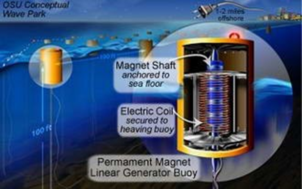
The design of the point-absorber OSU buoy is a bit more complicated. The coils is mounted in the moving part of the device, but instead of a single bar magnets, in the inner cylinder moored to the bottom there is a number of disc magnets, as shown in Fig. 8.6.
Everybody knows the devices called alternators – they produce electricity in our cars, and if they break down, there is a drama. Such alternators con- vert rotary motion to an electric signal. In contrast, the coil plus the rod including multiple magnets in the buoys constitute a device known as a linear alternator. More information about the design of such alternators specially designed to work in wave power converters can be found, e.g., in this document from Louisiana State University authored by Rajkumar Parthasarathy. We will not discuss any further the parameters of the electric signal generated, and how the signal is furtjer processed – the information of importance for us is that a single OSU buoy can generate as much as 50 kW of electric power. And at the end, it’s worth watching a short YouTube piece showing an OSU L10 converter and the way of how it is installed.