
2: Walls, Curtain Walls, Windows and Doors
- Page ID
- 88762

\( \newcommand{\vecs}[1]{\overset { \scriptstyle \rightharpoonup} {\mathbf{#1}} } \)
\( \newcommand{\vecd}[1]{\overset{-\!-\!\rightharpoonup}{\vphantom{a}\smash {#1}}} \)
\( \newcommand{\dsum}{\displaystyle\sum\limits} \)
\( \newcommand{\dint}{\displaystyle\int\limits} \)
\( \newcommand{\dlim}{\displaystyle\lim\limits} \)
\( \newcommand{\id}{\mathrm{id}}\) \( \newcommand{\Span}{\mathrm{span}}\)
( \newcommand{\kernel}{\mathrm{null}\,}\) \( \newcommand{\range}{\mathrm{range}\,}\)
\( \newcommand{\RealPart}{\mathrm{Re}}\) \( \newcommand{\ImaginaryPart}{\mathrm{Im}}\)
\( \newcommand{\Argument}{\mathrm{Arg}}\) \( \newcommand{\norm}[1]{\| #1 \|}\)
\( \newcommand{\inner}[2]{\langle #1, #2 \rangle}\)
\( \newcommand{\Span}{\mathrm{span}}\)
\( \newcommand{\id}{\mathrm{id}}\)
\( \newcommand{\Span}{\mathrm{span}}\)
\( \newcommand{\kernel}{\mathrm{null}\,}\)
\( \newcommand{\range}{\mathrm{range}\,}\)
\( \newcommand{\RealPart}{\mathrm{Re}}\)
\( \newcommand{\ImaginaryPart}{\mathrm{Im}}\)
\( \newcommand{\Argument}{\mathrm{Arg}}\)
\( \newcommand{\norm}[1]{\| #1 \|}\)
\( \newcommand{\inner}[2]{\langle #1, #2 \rangle}\)
\( \newcommand{\Span}{\mathrm{span}}\) \( \newcommand{\AA}{\unicode[.8,0]{x212B}}\)
\( \newcommand{\vectorA}[1]{\vec{#1}} % arrow\)
\( \newcommand{\vectorAt}[1]{\vec{\text{#1}}} % arrow\)
\( \newcommand{\vectorB}[1]{\overset { \scriptstyle \rightharpoonup} {\mathbf{#1}} } \)
\( \newcommand{\vectorC}[1]{\textbf{#1}} \)
\( \newcommand{\vectorD}[1]{\overrightarrow{#1}} \)
\( \newcommand{\vectorDt}[1]{\overrightarrow{\text{#1}}} \)
\( \newcommand{\vectE}[1]{\overset{-\!-\!\rightharpoonup}{\vphantom{a}\smash{\mathbf {#1}}}} \)
\( \newcommand{\vecs}[1]{\overset { \scriptstyle \rightharpoonup} {\mathbf{#1}} } \)
\(\newcommand{\longvect}{\overrightarrow}\)
\( \newcommand{\vecd}[1]{\overset{-\!-\!\rightharpoonup}{\vphantom{a}\smash {#1}}} \)
\(\newcommand{\avec}{\mathbf a}\) \(\newcommand{\bvec}{\mathbf b}\) \(\newcommand{\cvec}{\mathbf c}\) \(\newcommand{\dvec}{\mathbf d}\) \(\newcommand{\dtil}{\widetilde{\mathbf d}}\) \(\newcommand{\evec}{\mathbf e}\) \(\newcommand{\fvec}{\mathbf f}\) \(\newcommand{\nvec}{\mathbf n}\) \(\newcommand{\pvec}{\mathbf p}\) \(\newcommand{\qvec}{\mathbf q}\) \(\newcommand{\svec}{\mathbf s}\) \(\newcommand{\tvec}{\mathbf t}\) \(\newcommand{\uvec}{\mathbf u}\) \(\newcommand{\vvec}{\mathbf v}\) \(\newcommand{\wvec}{\mathbf w}\) \(\newcommand{\xvec}{\mathbf x}\) \(\newcommand{\yvec}{\mathbf y}\) \(\newcommand{\zvec}{\mathbf z}\) \(\newcommand{\rvec}{\mathbf r}\) \(\newcommand{\mvec}{\mathbf m}\) \(\newcommand{\zerovec}{\mathbf 0}\) \(\newcommand{\onevec}{\mathbf 1}\) \(\newcommand{\real}{\mathbb R}\) \(\newcommand{\twovec}[2]{\left[\begin{array}{r}#1 \\ #2 \end{array}\right]}\) \(\newcommand{\ctwovec}[2]{\left[\begin{array}{c}#1 \\ #2 \end{array}\right]}\) \(\newcommand{\threevec}[3]{\left[\begin{array}{r}#1 \\ #2 \\ #3 \end{array}\right]}\) \(\newcommand{\cthreevec}[3]{\left[\begin{array}{c}#1 \\ #2 \\ #3 \end{array}\right]}\) \(\newcommand{\fourvec}[4]{\left[\begin{array}{r}#1 \\ #2 \\ #3 \\ #4 \end{array}\right]}\) \(\newcommand{\cfourvec}[4]{\left[\begin{array}{c}#1 \\ #2 \\ #3 \\ #4 \end{array}\right]}\) \(\newcommand{\fivevec}[5]{\left[\begin{array}{r}#1 \\ #2 \\ #3 \\ #4 \\ #5 \\ \end{array}\right]}\) \(\newcommand{\cfivevec}[5]{\left[\begin{array}{c}#1 \\ #2 \\ #3 \\ #4 \\ #5 \\ \end{array}\right]}\) \(\newcommand{\mattwo}[4]{\left[\begin{array}{rr}#1 \amp #2 \\ #3 \amp #4 \\ \end{array}\right]}\) \(\newcommand{\laspan}[1]{\text{Span}\{#1\}}\) \(\newcommand{\bcal}{\cal B}\) \(\newcommand{\ccal}{\cal C}\) \(\newcommand{\scal}{\cal S}\) \(\newcommand{\wcal}{\cal W}\) \(\newcommand{\ecal}{\cal E}\) \(\newcommand{\coords}[2]{\left\{#1\right\}_{#2}}\) \(\newcommand{\gray}[1]{\color{gray}{#1}}\) \(\newcommand{\lgray}[1]{\color{lightgray}{#1}}\) \(\newcommand{\rank}{\operatorname{rank}}\) \(\newcommand{\row}{\text{Row}}\) \(\newcommand{\col}{\text{Col}}\) \(\renewcommand{\row}{\text{Row}}\) \(\newcommand{\nul}{\text{Nul}}\) \(\newcommand{\var}{\text{Var}}\) \(\newcommand{\corr}{\text{corr}}\) \(\newcommand{\len}[1]{\left|#1\right|}\) \(\newcommand{\bbar}{\overline{\bvec}}\) \(\newcommand{\bhat}{\widehat{\bvec}}\) \(\newcommand{\bperp}{\bvec^\perp}\) \(\newcommand{\xhat}{\widehat{\xvec}}\) \(\newcommand{\vhat}{\widehat{\vvec}}\) \(\newcommand{\uhat}{\widehat{\uvec}}\) \(\newcommand{\what}{\widehat{\wvec}}\) \(\newcommand{\Sighat}{\widehat{\Sigma}}\) \(\newcommand{\lt}{<}\) \(\newcommand{\gt}{>}\) \(\newcommand{\amp}{&}\) \(\definecolor{fillinmathshade}{gray}{0.9}\)2.1 TYPES OF WALLS
Basic Walls
Generic
A Basic Wall is a blank element with no applied materials. The default sizes available are 6, 8, and 12 inches thick. A material, pattern, texture, or color can be applied, and its depth altered. Other examples of Basic Wall are Generic Masonry, Generic Filled, Generic Brick, Brick on CMU, Brick on Metal Stud, CMU Insulated, CMU on Metal Stud, EIFS on Metal Stud, Interior Partition, Retaining wall, and GWB on Metal Stud.
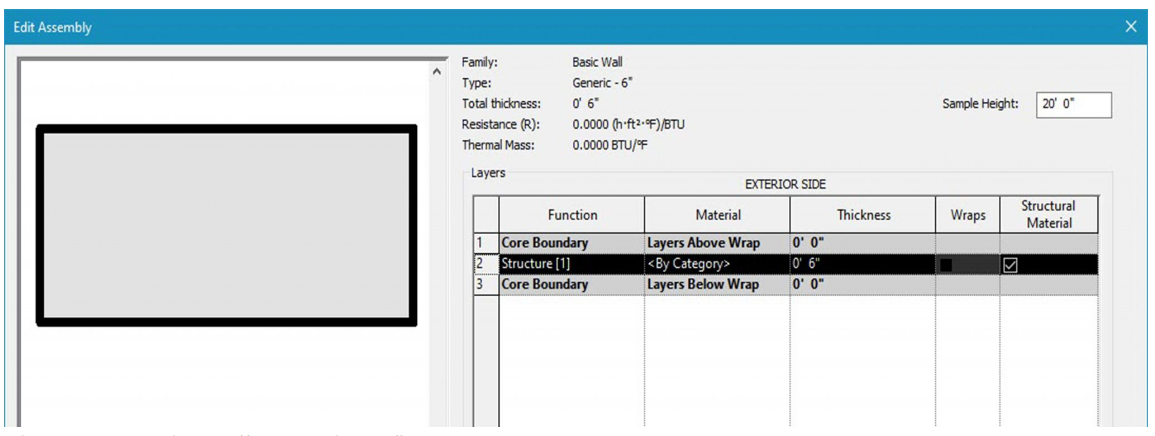
Figure 2.1 Basic Wall Generic – 6”
Generic Masonry
A generic masonry wall has a solid masonry material applied to it. The default sizes are 6, 8 and 12 inches thick.
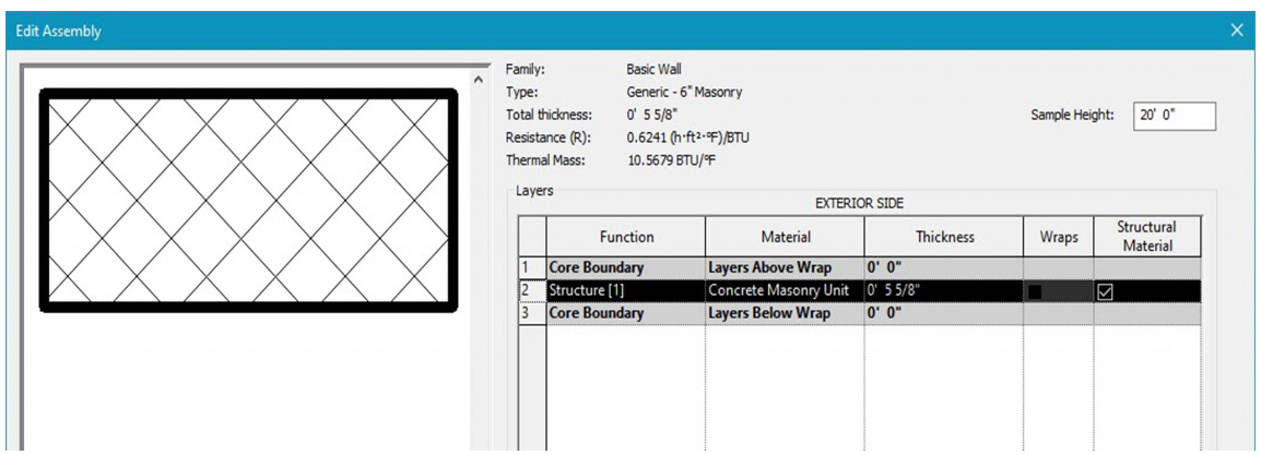
Figure 2.2 Basic Wall Generic – 6” Masonry
Generic Filled
A generic filled wall comes 8 inches thick and shows poched in section.
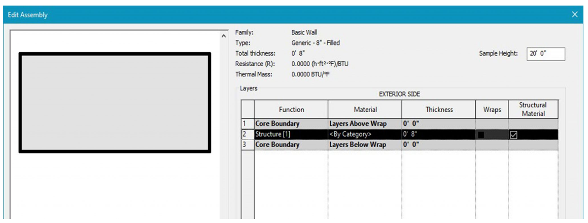
Figure 2.3 Basic Wall Generic – 8” – Filled
Generic Brick
A generic brick wall follows the nominal thickness of a 4-inch brick wall.
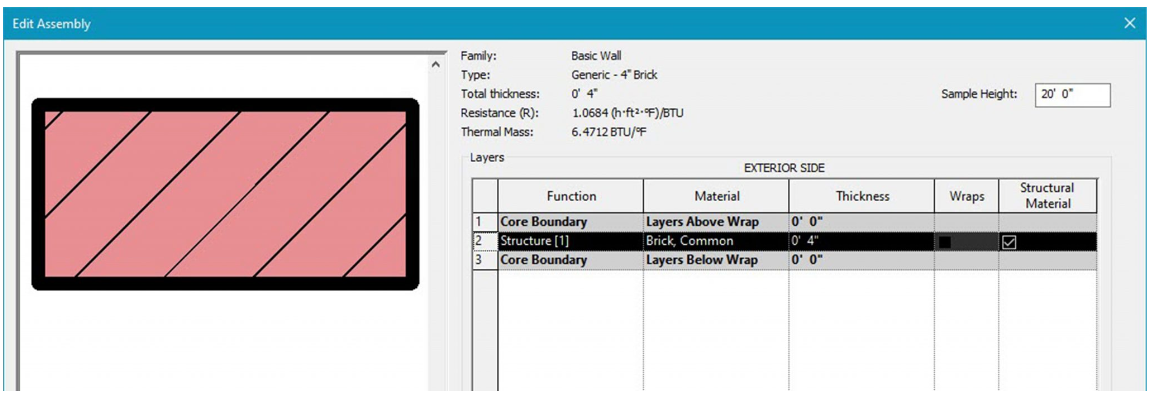
Figure 2.4 Basic Wall Generic – 4” Brick
Exterior walls
Exterior Brick on CMU
In section, this wall follows the correct layering of materials required by code to install brick over a structural CMU (Concrete Masonry Unit) wall.
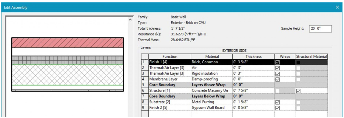
Figure 2.5 Basic Wall Exterior – Brick on CMU
Exterior Brick and CMU on MTL stud
In section, this wall follows the correct layering of materials required by code to install brick over a structural CMU (Concrete Masonry Unit) wall.
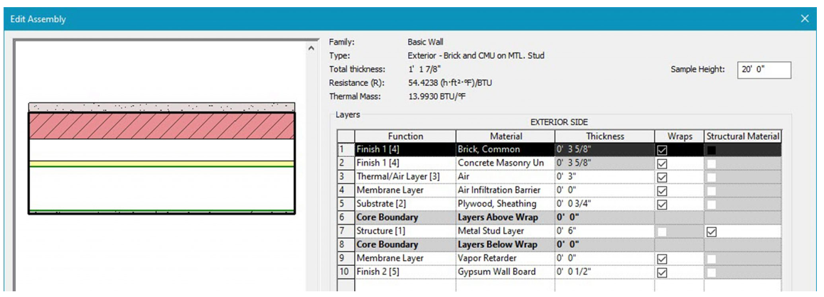
Figure 2.6 Basic Wall Exterior – Brick on CMU on MTL. Stud
Exterior Brick on MTL. Stud
In section, this wall follows the correct layering of materials required by code to install brick on a structural metal stud wall.
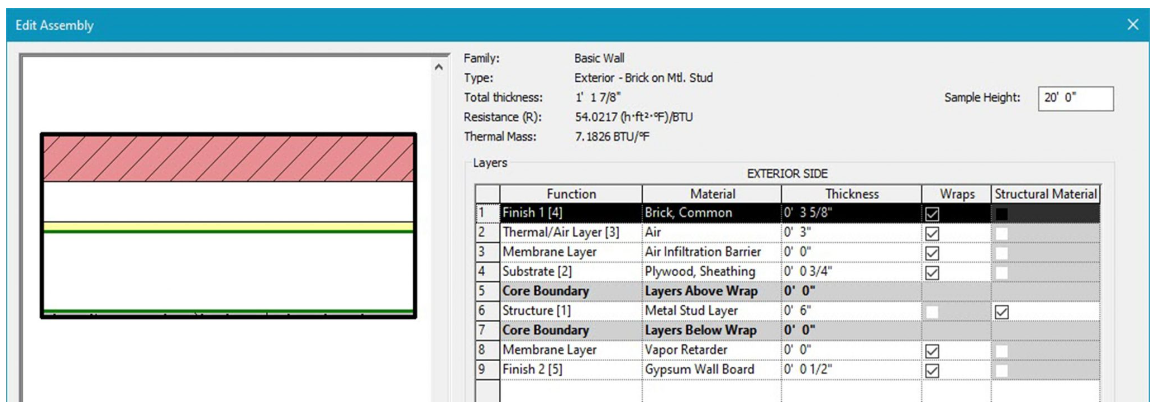
Figure 2.7 Basic Wall Exterior – Brick on Mtl. Stud
Exterior CMU Insulated
In section, this wall follows the correct layering of materials required by code to install insulated CMU blocks.
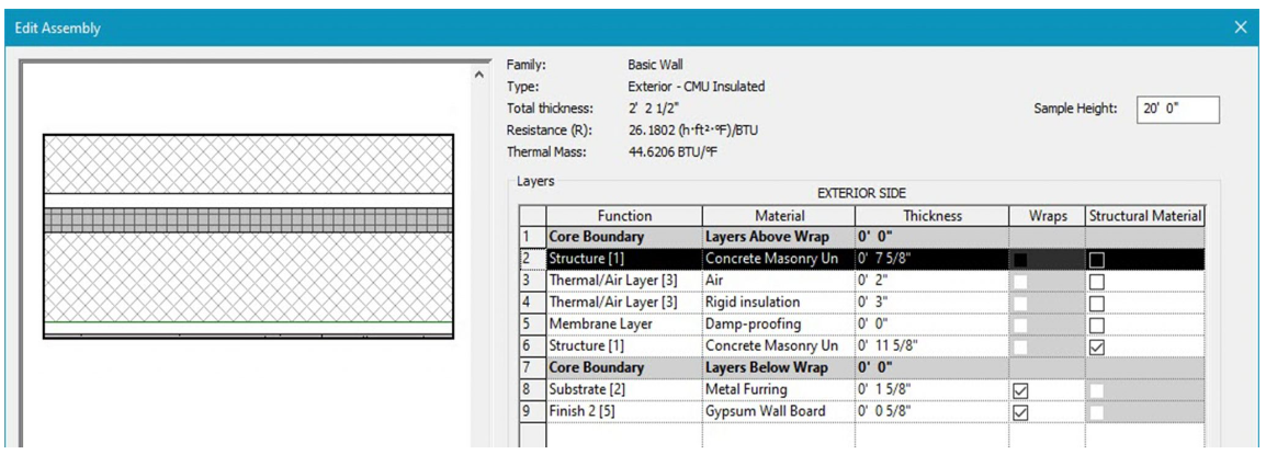
Figure 2.8 Basic Wall Exterior – CMU Insulated
Exterior CMU on MTL. Stud
In section, this wall follows the correct layering of materials required by code to install CMU as the exterior facing with a metal stud wall on the interior.
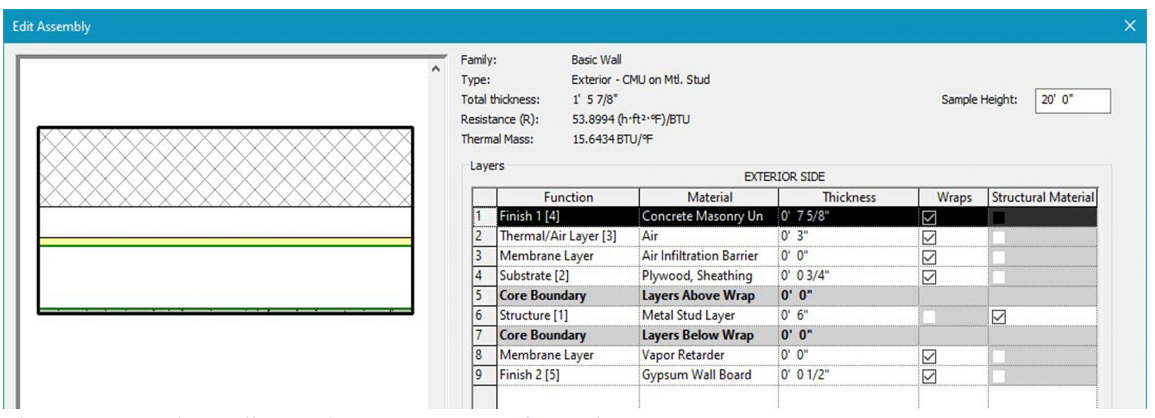
Figure 2.9 Basic Wall Exterior – CMU on Mtl. Stud
Exterior EIFS on Mtl. Stud
In section, this wall follows the correct layering of materials required by code to install an Exterior Insulation and Finishing System on the exterior facing of a metal stud wall.
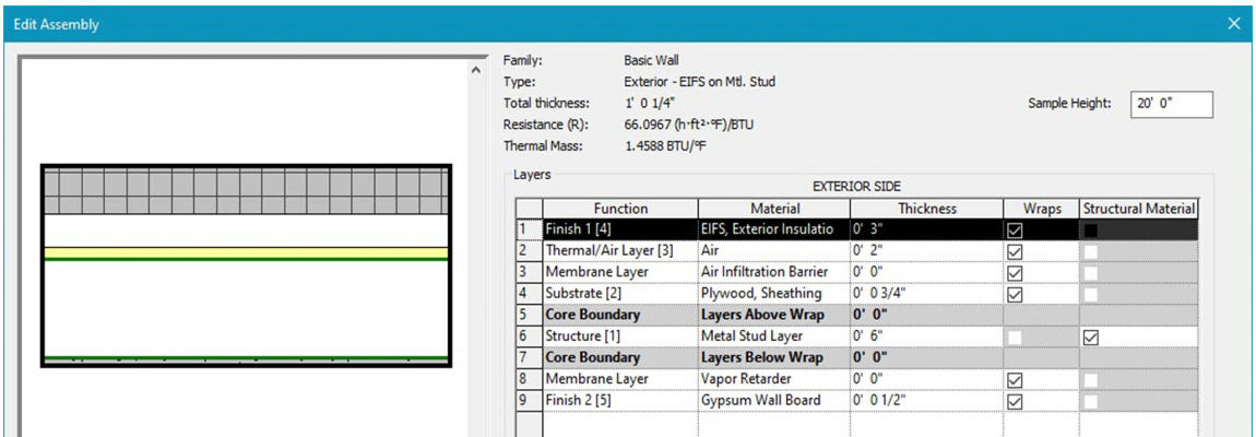
Figure 2.10 Basic Wall Exterior – EIFS on Mtl. Stud
Interior Walls
Interior Partition (1-hr)
An interior partition wall has metal studs at its core with 1 hour rated gypsum board on both facings. The default wall sizes are 3-1/8”, 4-7/8” and 5-1/2” thick.
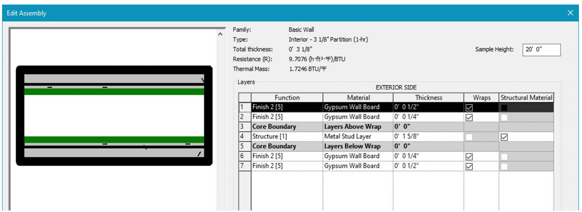
Figure 2.11 Basic Wall Interior – 3 1/8” Partition (1-hr)
Interior Partition (2-hr)
An interior partition wall has metal studs at its core with 2 hour rated gypsum board on both facings. The default wall sizes are 5” and 6-1/8” thick.
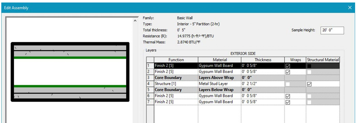
Figure 2.12 Basic Wall Interior – 5” Partition (2-hr)
Other Walls
Retaining 12” Concrete
A retaining wall is made from concrete that is cast-in-place, on-site.
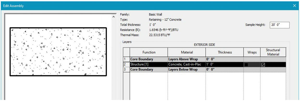
Figure 2.13 Basic Wall Retaining – 12” Concrete
Soffit ½” GWB and Metal Stud
A soffit is usually the eave overhang that connects the roof back to the exterior face of the wall. It can also be the material area underneath a balcony or other such elements.
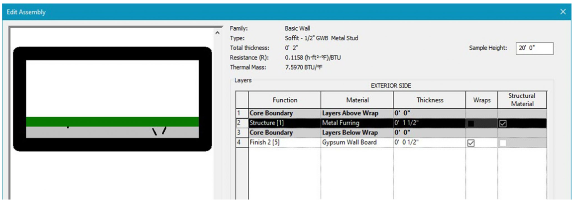
Figure 2.14 Basic Wall Soffit – ½” GWB Metal Stud
Foundation Concrete
Foundation concrete is used underneath structural walls to create a soil retaining barrier. These elements are often referred to as footings and are always thicker than the structural wall above.
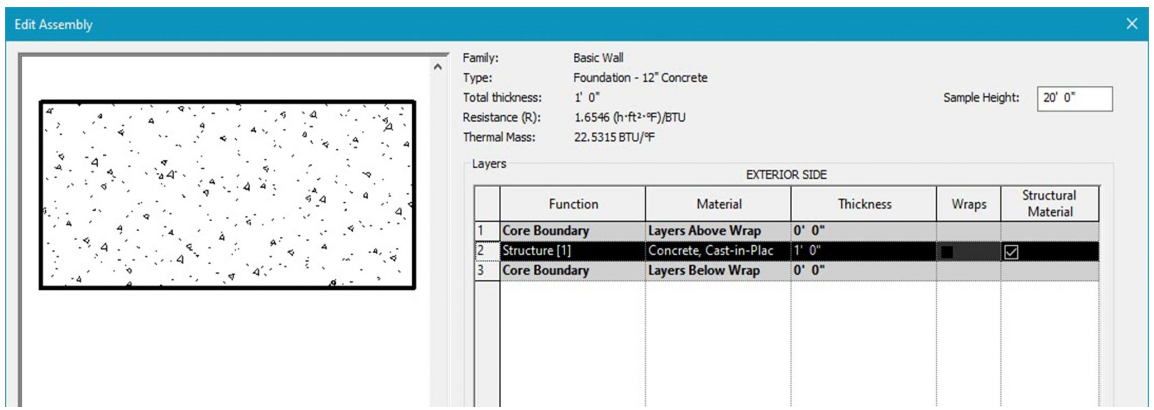
Figure 2.15 Basic Wall Foundation – 12” Concrete
Revit Curtain Walls
Curtain Wall
A glass curtain wall system is connected from the building’s floor plates typically seen on high-rise buildings. These walls do not carry any loads of floors, roofs, or structure to the ground. The Curtain Wall type in Revit is a blank glass wall with no set parameters as a base for grids and mullions to be designed.
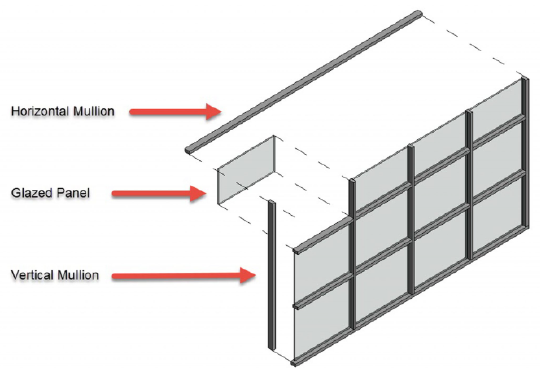
Figure 2.16 Curtain wall in 3D view and cut in section
Exterior Glazing
Exterior Glazing has a preset grid where the parameters can be altered and designed through the Properties Palette.
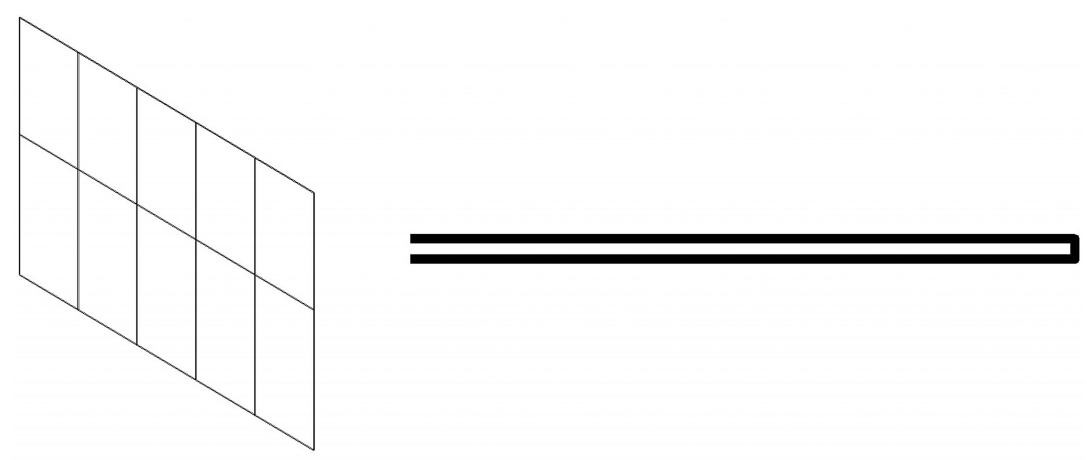
Figure 2.17 Exterior Glazing in 3D view and cut in section
Storefront
A storefront system is typically installed between floor plates typically low-rise and commercial buildings. The Storefront wall option offers a ready-to-go wall with a set grid and set mullions that can be altered and designed through the Properties Palette.
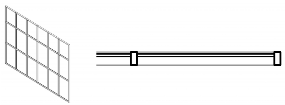
Figure 2.18 Storefront in 3D view and cut in section
Stacked Wall
Exterior Brick over CMU with Metal Stud
The Revit Stacked Wall option offers a wall built from two different materials stacked one on top of the other. In this specific type the lower portion is a CMU block and the top is a Brick wall tied to a metal stud wall. These walls can be modified or designed using the Properties Palette.
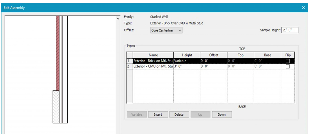
Figure 2.19 Stacked Wall Exterior – Brick over CMU w Metal Stud
2.2 CREATE AND MODIFY WALLS
This Building Information Modeling book will continually build in one tutorial file through every chapter.
- Start a New Project and select the Architectural Template
- Use Figure 2.20 to add the levels
 in an elevation view
 - Use Figure 2.21 to add grid lines in the Level 1 view at 20 feet. Make sure to lock the grid lines using the pin tool

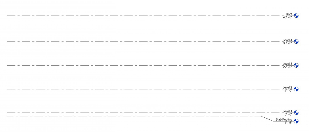
Figure 2.20 Project Levels in the East elevation
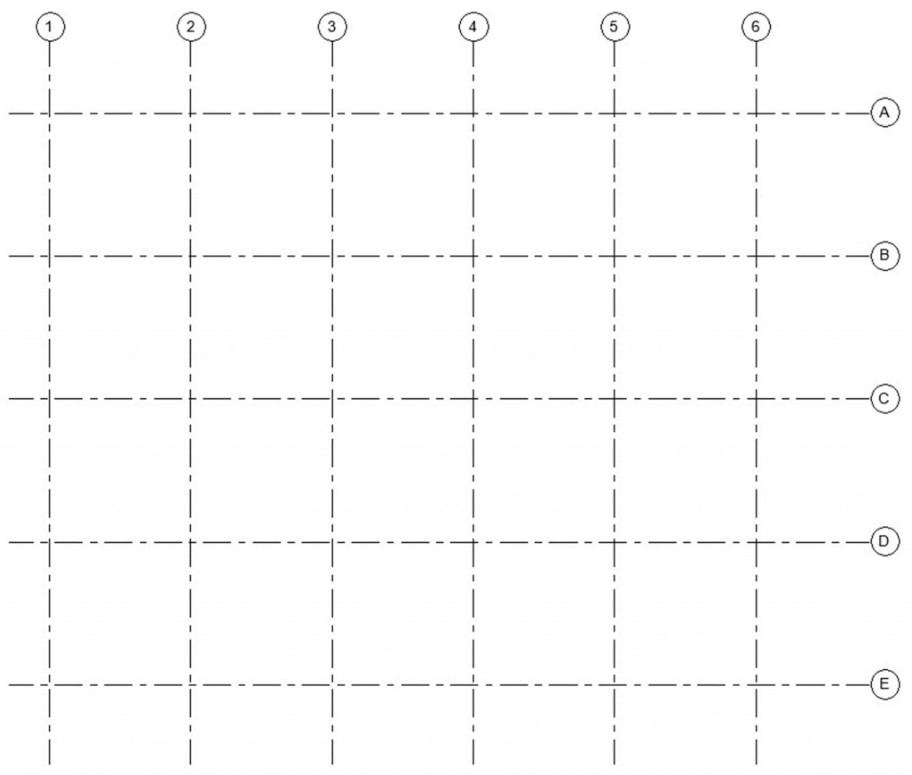
Figure 2.21 Grid Lines in the Level 1 view
Create a wall using the line tool
- In the Level 1 view, click to open the Architecture tab
- Click the Wall icon
 from the Ribbon, under the Build panel
 - Use the Type Selector to choose the Generic – 12”
- In the Properties Palette set the following parameters
- Location Line: Wall Centerline
- Base Constraint: Level 1
- Top Constraint: Up to level: Roof Level
- Under the Draw panel, click the Line tool

- Click once to begin a wall from Figure 2.22
- Drag the cursor and type the dimension
- Press Enter to complete the first wall
- Drag and type the dimension until all 5 walls are placed
- Press ESC twice to exit the command
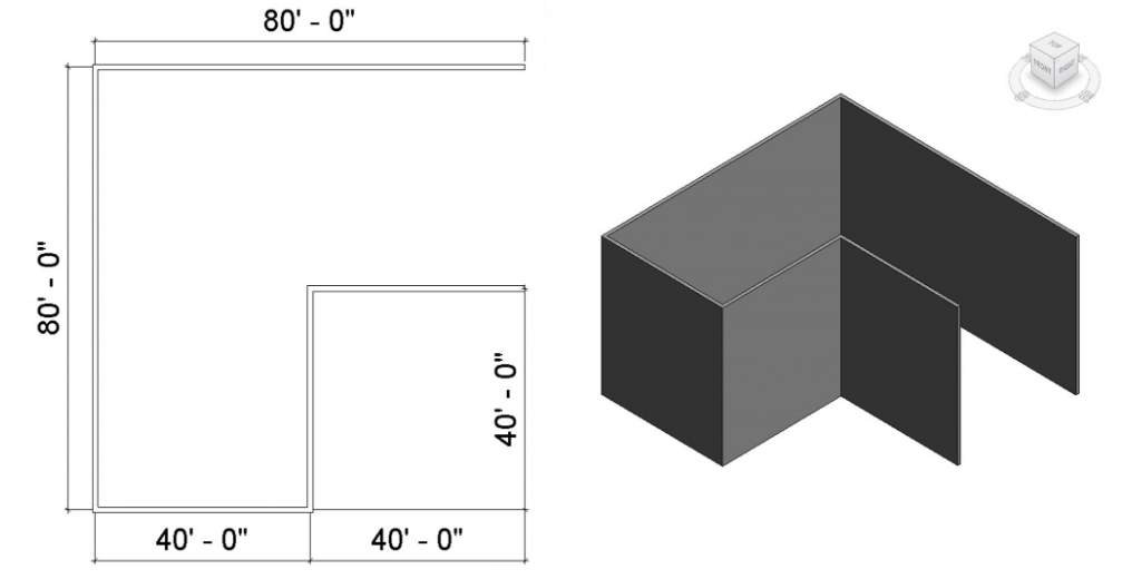
Figure 2.22 Generic 12” walls in plan view and 3D view
TIP
- The Options Bar is also used to set parameters
- To view the model in 3D, click the Default 3D View icon
 from the Quick Access Tool Bar
Modify a wall
- In the Level 1 or 3D view, click to open the Architecture tab
- Click the wall icon
- Use the Type Selector to choose the Generic – 4″ Brick
- Click the Edit Type button

- Click the Duplicate button
- Rename the duplicate “Generic – 4” Brick w/ Reveals
- In the Type Properties window, next to Structures, click Edit…
- At the bottom of the window, click the Preview button to view the wall system
- Use the View drop-down menu to choose Section
- Click the Reveals button
- Click the Add button
- Select the Default line
- Navigate through the Imperial Library to find the profile
- Profiles folder
- Wall folder
- Choose the Wall Sweep – Brick Soldier Couse
- Click Open
- Use the drop-down to change from Default to Reveal – Brick Course: 3 Brick
- Click OK to close the Reveals, Edit Assembly, and Type Properties windows
- In the 3D view, select the buildings West wall
- Use the Type Selector to change the wall to CMU – Insulated
- Change the Top Constraint to Level 3
- Open the Level 3 View
- Click the wall icon
- Change the Top Constraints to Roof
- Draw a wall to fill in the top half of the West wall elevation
- Select the CMU – Insulated wall
- Click the Edit Profile icon

- Following Figure 2.23 redraw the profile of the wall
- Click the green checkmark
 to complete the modified wall
 - With the modified CMU wall selected click the Attach Top/Base icon
 on the ribbon.
 - Select the Brick wall above the CMU wall
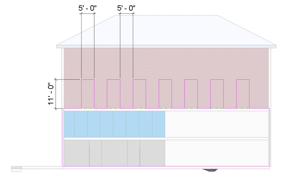
Figure 2.23 Modified profile on CMU wall
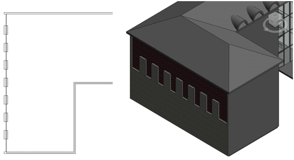
Figure 2.24 Stacked exterior wall shown in the Level 3 plan view and in the 3D view
TIP
Create interior walls
- In the Level 1 view click the Architecture tab
- Click the Wall icon from the ribbon, under the Build panel
- Use the Type Selector to choose the Interior 4-7/8” Partition (1-hr)
- In the Properties Palette set the following parameters
- Location Line: Wall Centerline
- Base Constraint: Level 1
- Top Constraint: Up to level: Level 2
- Under the Draw panel, click the Line tool
- Draw 8 enclosed rooms as shown in Figure 2.25
- Click the Architecture tab
- Click the Wall icon
- Use the Type Selector to choose the Interior 3-1/8” Partition (1-hr)
- In the Properties Palette change the following parameters
- Top Constraint: Unconnected
- Unconnected Height: 3’6”
- Refer to Figure 2.26 to draw the cubicle partition walls
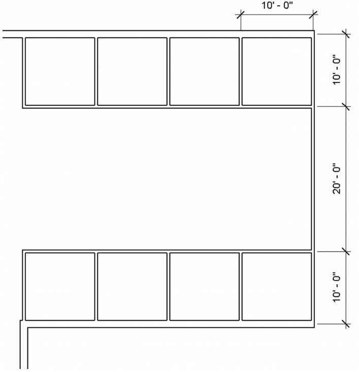
Figure 2.25 Eight enclosed rooms with dimension lines
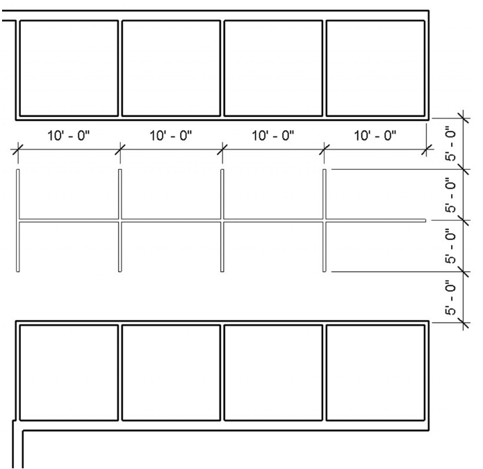
Figure 2.26 Interior walls with dimension lines
TIP
- The Options Bar is also used to set parameters
- Press the ESC key once to discontinue a wall and begin a new wall in a different location
Create curved walls
- In the Level 1 view, select the Wall icon from the ribbon, under the Build panel
- Use the Type Selector to choose the Interior 4-7/8” Partition (1-hr)
- In the Properties Palette set the following parameters
- Location Line: Wall Centerline
- Base Constraint: Level 1
- Top Constraint: Up to level: Level 2
- Under the Draw panel, use the Start-End-Radius Arc tool
 and the line tool to draw the rooms. Refer to the dimensions in Figure 2.27
 - Create 2 more identical rooms using the Copy
 and Paste icons
- Center each on the intersection grid lines using the Move tool

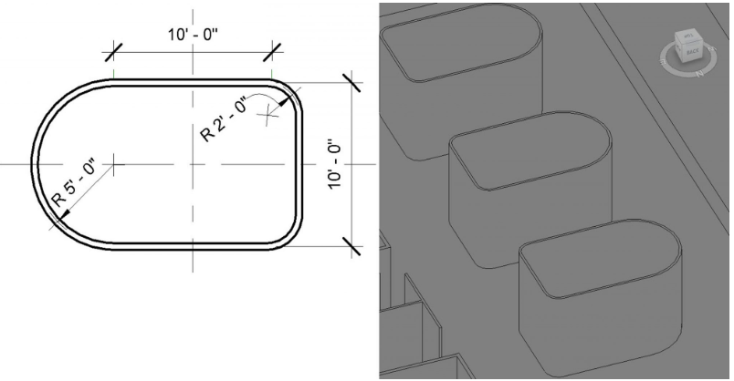
Figure 2.27 Dimensions for the room with curved walls
Add an opening
- In the 3D view, Click the Architecture tab
- On the ribbon, click the Wall icon
 from the Opening panel
 - Select the wall to cut an opening in
- The cursor will change to a draw rectangle tool

- Click once to begin the opening
- Drag the cursor diagonally and click to place the opening
- Press the ESC key twice to exit the command
- Select the opening and use the witness lines to change the dimensions as shown in Figure 2.28.
- Create identical openings for the other 2 rooms
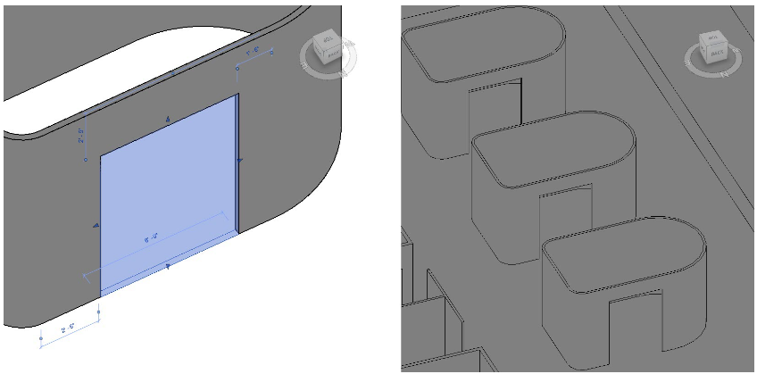
Figure 2.28 Wall Opening with witness line dimensions
Create a Curtain Wall
- Click the Architecture tab
- In the Level 2 view, click the Wall icon from the ribbon, under the Build panel
- Use the Type Selector to choose the Curtain Wall 1
- In the Properties Palette set the following parameters
- Location Line: Wall Centerline
- Base Constraint: Level 1
- Top Constraint: Up to level: Level 2
- Under the Draw panel, choose the Line tool
- Draw one wall as shown in Figure 2.29
- Press the ESC key twice to exit the command
- In the 3D view, select the Curtain Grid icon
 from the ribbon, under the Build panel
 - Hover the cursor over the curtain walls top edge and click to place vertical grid lines every 5 feet as shown in Figure 2.30
- Hover the cursor over the curtain walls side edge and click to place horizontal grid lines every 11 feet as shown in Figure 2.30
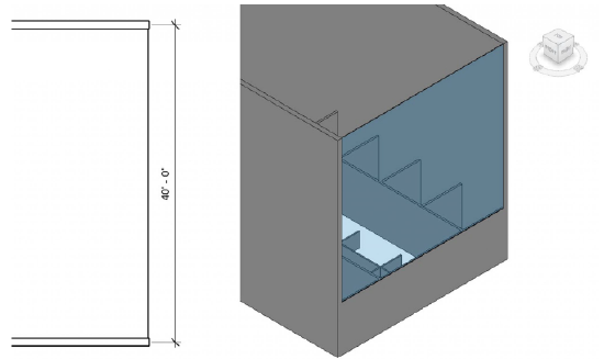
Figure 2.29 Curtain Wall 1 shown in plan view and in 3D view
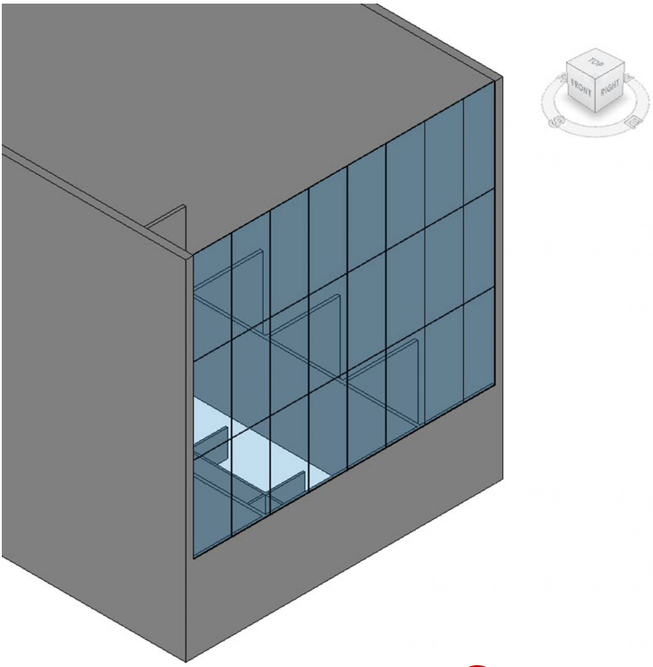
Figure 2.30 Curtain Wall 1 with added grid lines
Modify a Curtain Wall
- Click the Architecture tab
- In the Level 1 view, select the Wall icon from the ribbon, under the Build panel
- Use the Type Selector to choose the Curtain Wall 1
- In the Properties Palette set the following parameters
- Location Line: Wall Centerline
- Base Constraint: Level 1
- Top Constraint: Up to level: Roof Level
- Click the Edit Type button in the Properties Palette
- The Type Properties window will open, click the Duplicate button as shown in Figure 2.31
- Name the Duplicate My Curtain Wall
- Change the following parameters
- Construction
- Curtain Panel: System Panel: Glazed
- Join Condition: Border and Vertical Grid Conditions
- Vertical Grid
- Layout: Fixed Distance
- Spacing: 5’ 0”
- Horizontal Grid
- Layout: Fixed Distance
- Spacing: 11’ 0”
- Vertical Mullions
- Interior Type: Rectangular Mullion: 1.5” X 2.5” rectangular
- Border Type 1: Rectangular Mullion: 1.5” X 2.5” rectangular
- Horizontal Mullions
- Interior Type: Rectangular Mullion: 1.5” X 2.5” rectangular
- Border Type 1: Rectangular Mullion: 1.5” X 2.5” rectangular
- Click OK to accept parameters
- Construction
- Under the Draw panel, click the Line tool
- Draw three walls as shown in Figure 2.32
- Press the ESC key twice to exit the command
- Select the Modify icon
 on the ribbon
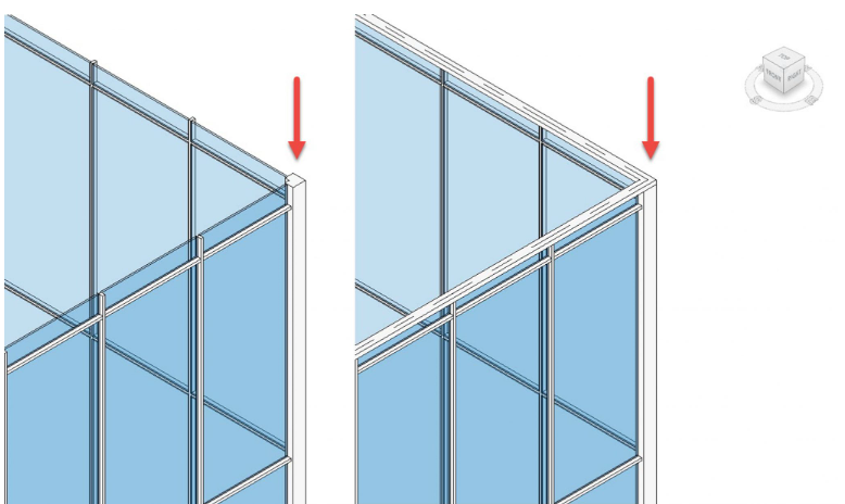
 - Select the vertical corner mullion
- Right–click and click the Select Mullions option, then click On Gridline from the submenu
- On the ribbon, click the Unpin tool

- Use the Type Selector to change the mullion to L Corner Mullion: 5” X 5”, use Figure 2.33 for reference
- Repeat steps 11 through 15 for the other corner condition
- On the ribbon, select the Mullion icon

- Select the top edge of the curtain wall to add mullions to finish off the wall as shown in Figure 2.33
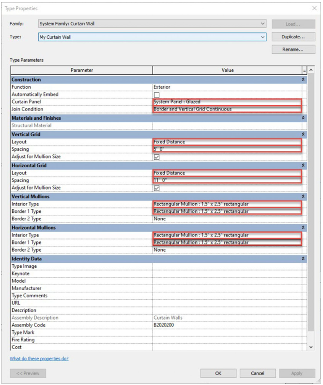
Figure 2.31 Curtain wall Type Parameters
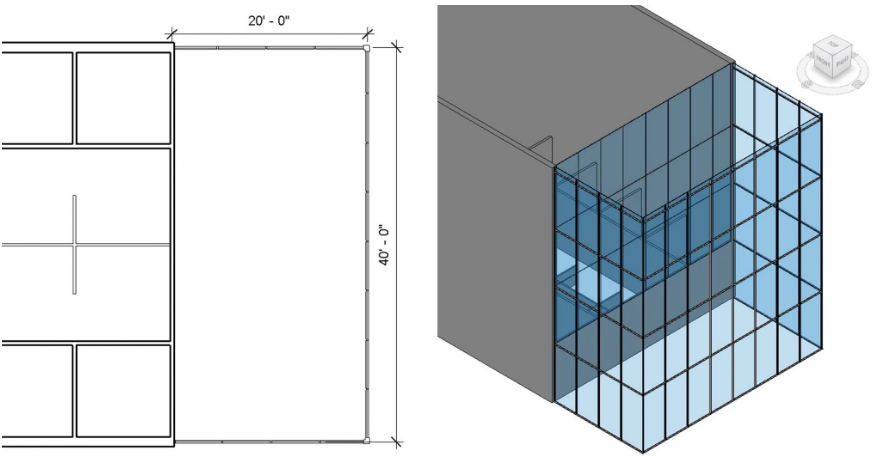
Figure 2.32 My Curtain Wall in plan view and in 3D view
 S
S
Figure 2.33 Modified corner mullions (left) and added top mullion (right)
TIP
Hover over an item and press the Tab key to cycle through the selection options
Embed and edit a curtain wall
- Change the South curtain wall type to Storefront
- Click the Edit Type button in the Properties Palette
- The Type Properties window will open, click the Duplicate button
- Name the Duplicate My Storefront Wall
- Change the following parameters
- Vertical Grid
- Layout: Fixed Distance
- Horizontal Grid
- Spacing: 11’ 0”
- Click OK to accept the changes
- Vertical Grid
- Hover the cursor over one of the bottom two center mullions
- Select the mullion and click the Unpin tool on the ribbon
- Press the Delete key
- Repeat steps 7 through 9 on the other bottom center mullion
- Hover the cursor over one of the center panes of glass
- Select the glass pane and click the Unpin tool on the ribbon
- In the Properties palette, click the Edit Type button
- The Type Properties window will open
- Click the Load button
- Open the Doors folder
- Select the Door-Curtain-Wall-Single-Glass
- Click Open
- Click OK
- Select the other center glass pane
- Select the glass pane and click the Unpin tool on the ribbon
- Use the Type Selector to change the glass pane to the Door-Curtain-Wall-Single-Glass
- In the Level 1 view, adjust the door swing directions as shown in Figure 2.34
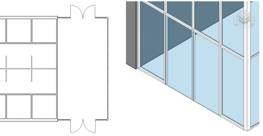
Figure 2.34 Storefront doors shown in plan and in 3D view
TIP
- Hover over an item and press the Tab key to cycle through the selection options
- With an element selected, press the Space bar to cycle through the rotations or position options
2.3 PLACING DOORS
- Click the Architecture tab
- In the Level 1 view, click the Door icon
 from the ribbon, under the Build panel
 - Use the Type Selector to choose the Single-Flush 36” X 84”
- Click to place doors as shown in Figure 2.35
- Select each door and use the witness lines to adjust the placement to 2’6” between the open door and the neighboring wall. See Figure 2.35 for reference
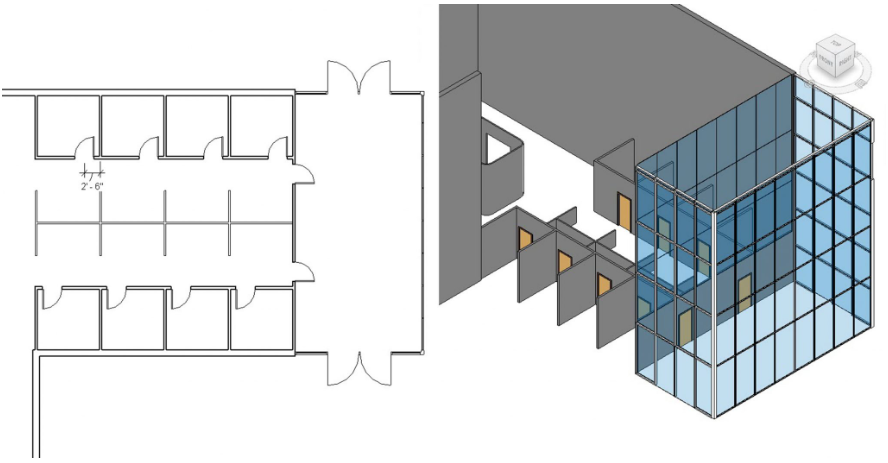
Figure 2.35 Placed doors in plan view and in 3D view
(One wall in the 3D view is hidden to better show the door placements)
2.4 PLACING WINDOWS
- Click the Architecture tab
- In the Level 1 view, select the Window icon
 from the ribbon, under the Build panel
 - Use the Type Selector to choose the Fixed 36” X 72” window
- Click to place the windows as shown in Figure 2.36
- On the ribbon, select the Align Dimension icon

- Hover the cursor over the center of the window, when the centerline highlights blue, click to place a dimension line
- Click to add the remaining 3 windows.
- Drag the dimension line outside of the building
- Click anywhere on the dimension line to finish placing
- Press the ESC twice to exit the command
- Select the dimensions and click the
 to activate equally spacing the windows
 - Follow steps 5 through 11 for the second set of windows
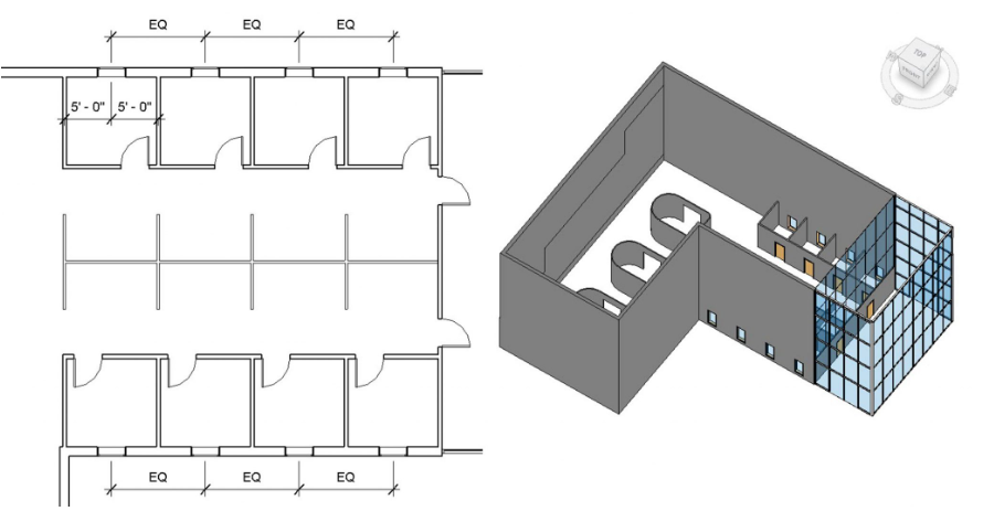
Figure 2.36 Placed windows in plan view and in 3D view