
3: Floors, Roofs and Ceilings
- Page ID
- 88763

\( \newcommand{\vecs}[1]{\overset { \scriptstyle \rightharpoonup} {\mathbf{#1}} } \)
\( \newcommand{\vecd}[1]{\overset{-\!-\!\rightharpoonup}{\vphantom{a}\smash {#1}}} \)
\( \newcommand{\dsum}{\displaystyle\sum\limits} \)
\( \newcommand{\dint}{\displaystyle\int\limits} \)
\( \newcommand{\dlim}{\displaystyle\lim\limits} \)
\( \newcommand{\id}{\mathrm{id}}\) \( \newcommand{\Span}{\mathrm{span}}\)
( \newcommand{\kernel}{\mathrm{null}\,}\) \( \newcommand{\range}{\mathrm{range}\,}\)
\( \newcommand{\RealPart}{\mathrm{Re}}\) \( \newcommand{\ImaginaryPart}{\mathrm{Im}}\)
\( \newcommand{\Argument}{\mathrm{Arg}}\) \( \newcommand{\norm}[1]{\| #1 \|}\)
\( \newcommand{\inner}[2]{\langle #1, #2 \rangle}\)
\( \newcommand{\Span}{\mathrm{span}}\)
\( \newcommand{\id}{\mathrm{id}}\)
\( \newcommand{\Span}{\mathrm{span}}\)
\( \newcommand{\kernel}{\mathrm{null}\,}\)
\( \newcommand{\range}{\mathrm{range}\,}\)
\( \newcommand{\RealPart}{\mathrm{Re}}\)
\( \newcommand{\ImaginaryPart}{\mathrm{Im}}\)
\( \newcommand{\Argument}{\mathrm{Arg}}\)
\( \newcommand{\norm}[1]{\| #1 \|}\)
\( \newcommand{\inner}[2]{\langle #1, #2 \rangle}\)
\( \newcommand{\Span}{\mathrm{span}}\) \( \newcommand{\AA}{\unicode[.8,0]{x212B}}\)
\( \newcommand{\vectorA}[1]{\vec{#1}} % arrow\)
\( \newcommand{\vectorAt}[1]{\vec{\text{#1}}} % arrow\)
\( \newcommand{\vectorB}[1]{\overset { \scriptstyle \rightharpoonup} {\mathbf{#1}} } \)
\( \newcommand{\vectorC}[1]{\textbf{#1}} \)
\( \newcommand{\vectorD}[1]{\overrightarrow{#1}} \)
\( \newcommand{\vectorDt}[1]{\overrightarrow{\text{#1}}} \)
\( \newcommand{\vectE}[1]{\overset{-\!-\!\rightharpoonup}{\vphantom{a}\smash{\mathbf {#1}}}} \)
\( \newcommand{\vecs}[1]{\overset { \scriptstyle \rightharpoonup} {\mathbf{#1}} } \)
\(\newcommand{\longvect}{\overrightarrow}\)
\( \newcommand{\vecd}[1]{\overset{-\!-\!\rightharpoonup}{\vphantom{a}\smash {#1}}} \)
\(\newcommand{\avec}{\mathbf a}\) \(\newcommand{\bvec}{\mathbf b}\) \(\newcommand{\cvec}{\mathbf c}\) \(\newcommand{\dvec}{\mathbf d}\) \(\newcommand{\dtil}{\widetilde{\mathbf d}}\) \(\newcommand{\evec}{\mathbf e}\) \(\newcommand{\fvec}{\mathbf f}\) \(\newcommand{\nvec}{\mathbf n}\) \(\newcommand{\pvec}{\mathbf p}\) \(\newcommand{\qvec}{\mathbf q}\) \(\newcommand{\svec}{\mathbf s}\) \(\newcommand{\tvec}{\mathbf t}\) \(\newcommand{\uvec}{\mathbf u}\) \(\newcommand{\vvec}{\mathbf v}\) \(\newcommand{\wvec}{\mathbf w}\) \(\newcommand{\xvec}{\mathbf x}\) \(\newcommand{\yvec}{\mathbf y}\) \(\newcommand{\zvec}{\mathbf z}\) \(\newcommand{\rvec}{\mathbf r}\) \(\newcommand{\mvec}{\mathbf m}\) \(\newcommand{\zerovec}{\mathbf 0}\) \(\newcommand{\onevec}{\mathbf 1}\) \(\newcommand{\real}{\mathbb R}\) \(\newcommand{\twovec}[2]{\left[\begin{array}{r}#1 \\ #2 \end{array}\right]}\) \(\newcommand{\ctwovec}[2]{\left[\begin{array}{c}#1 \\ #2 \end{array}\right]}\) \(\newcommand{\threevec}[3]{\left[\begin{array}{r}#1 \\ #2 \\ #3 \end{array}\right]}\) \(\newcommand{\cthreevec}[3]{\left[\begin{array}{c}#1 \\ #2 \\ #3 \end{array}\right]}\) \(\newcommand{\fourvec}[4]{\left[\begin{array}{r}#1 \\ #2 \\ #3 \\ #4 \end{array}\right]}\) \(\newcommand{\cfourvec}[4]{\left[\begin{array}{c}#1 \\ #2 \\ #3 \\ #4 \end{array}\right]}\) \(\newcommand{\fivevec}[5]{\left[\begin{array}{r}#1 \\ #2 \\ #3 \\ #4 \\ #5 \\ \end{array}\right]}\) \(\newcommand{\cfivevec}[5]{\left[\begin{array}{c}#1 \\ #2 \\ #3 \\ #4 \\ #5 \\ \end{array}\right]}\) \(\newcommand{\mattwo}[4]{\left[\begin{array}{rr}#1 \amp #2 \\ #3 \amp #4 \\ \end{array}\right]}\) \(\newcommand{\laspan}[1]{\text{Span}\{#1\}}\) \(\newcommand{\bcal}{\cal B}\) \(\newcommand{\ccal}{\cal C}\) \(\newcommand{\scal}{\cal S}\) \(\newcommand{\wcal}{\cal W}\) \(\newcommand{\ecal}{\cal E}\) \(\newcommand{\coords}[2]{\left\{#1\right\}_{#2}}\) \(\newcommand{\gray}[1]{\color{gray}{#1}}\) \(\newcommand{\lgray}[1]{\color{lightgray}{#1}}\) \(\newcommand{\rank}{\operatorname{rank}}\) \(\newcommand{\row}{\text{Row}}\) \(\newcommand{\col}{\text{Col}}\) \(\renewcommand{\row}{\text{Row}}\) \(\newcommand{\nul}{\text{Nul}}\) \(\newcommand{\var}{\text{Var}}\) \(\newcommand{\corr}{\text{corr}}\) \(\newcommand{\len}[1]{\left|#1\right|}\) \(\newcommand{\bbar}{\overline{\bvec}}\) \(\newcommand{\bhat}{\widehat{\bvec}}\) \(\newcommand{\bperp}{\bvec^\perp}\) \(\newcommand{\xhat}{\widehat{\xvec}}\) \(\newcommand{\vhat}{\widehat{\vvec}}\) \(\newcommand{\uhat}{\widehat{\uvec}}\) \(\newcommand{\what}{\widehat{\wvec}}\) \(\newcommand{\Sighat}{\widehat{\Sigma}}\) \(\newcommand{\lt}{<}\) \(\newcommand{\gt}{>}\) \(\newcommand{\amp}{&}\) \(\definecolor{fillinmathshade}{gray}{0.9}\)3.1 TYPES OF FLOORS
Basic Floor
Generic Floor
A Generic Floor is a blank element with no applied materials. The default size is 12 inches thick. A material, pattern, texture, or color can be applied, and its depth altered.
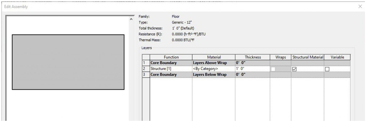
Figure 3.1 Floor Generic – 12”
Generic Filled
A generic filled floor comes 12 inches thick and shows poched in section.
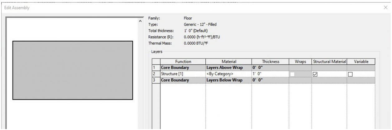
Figure 3.2 Floor Generic – 12” – Filled
Detailed Floors
LW Concrete on Metal Deck
In section, this wall follows the correct layering of materials required by code to install Light Weight concrete over metal decking material.
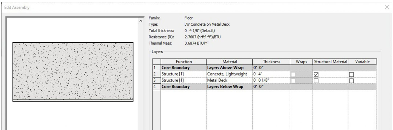
Figure 3.3LW Concrete on Metal Deck
3” LW Concrete on 2” Metal Deck
In section, this wall follows the correct layering of materials required by code to install Light Weight concrete over metal decking. The 3 inches refers to the thickness of concrete above the corrugated metal while the 2 inches refers to the depth of the corrugated metal deck channels.
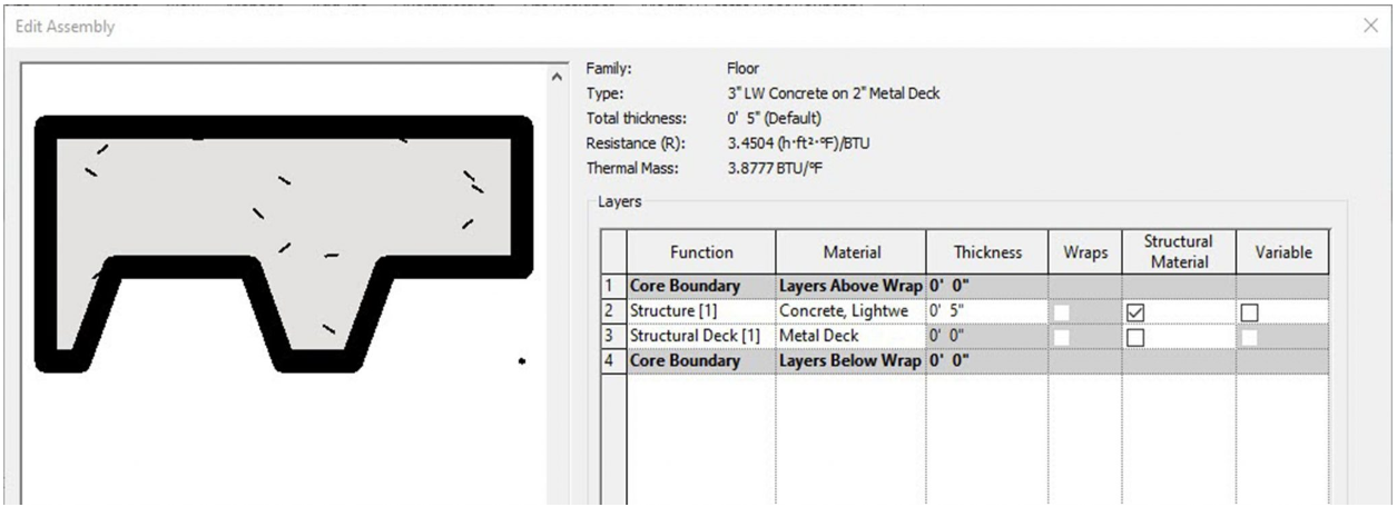
Figure 3.4 Floor 3” LW Concrete on 2” Metal Deck
Steel Bar Joist 14” – VCT on Concrete
In section, this wall follows the correct layering of materials required by code to install vinyl composition tile over lightweight concrete and metal decking. This floor system lays on top of structural steel joists that are 14” in depth.
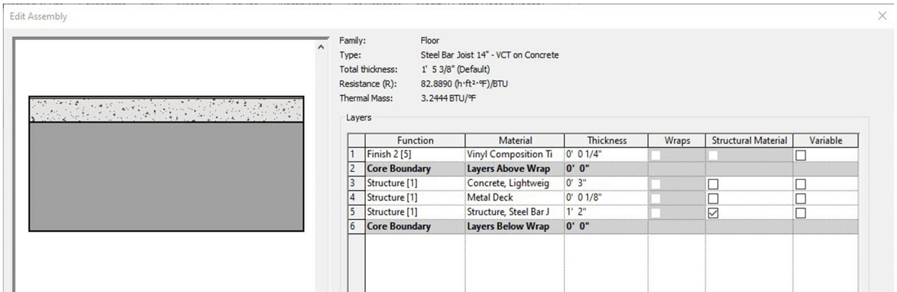
Figure 3.5 Floor Steel Bar Joist 14” – VCT on Concrete
Wood Joist 10” – Ceramic Tile
In section, this wall follows the correct layering of materials required by code to install ceramic tile over a wooden structure. This floor system lays on top of structural wood joists that are 10” in depth.
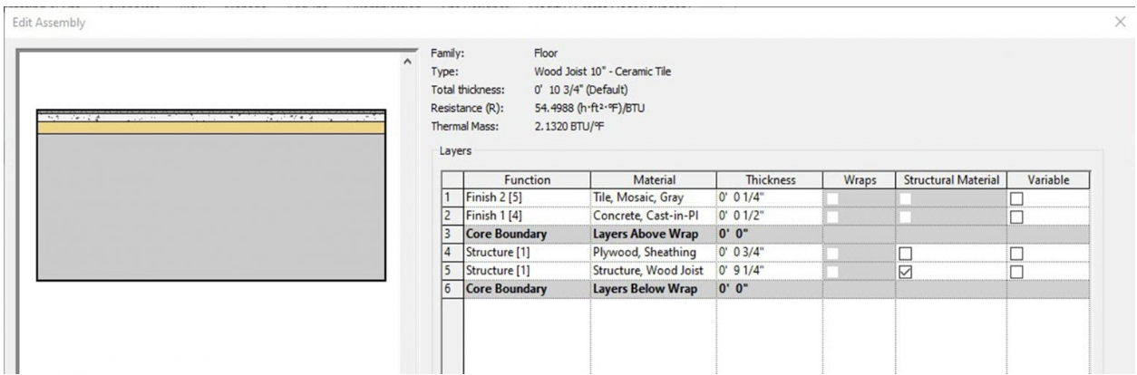
Figure 3.6 Floor Wood Joist 10” – Ceramic Tile
Wood Joist 10” – Wood Finish
In section, this wall follows the correct layering of materials required by code to install wood flooring over a wooden structure. This floor system lays on top of structural wood joists that are 10” in depth.
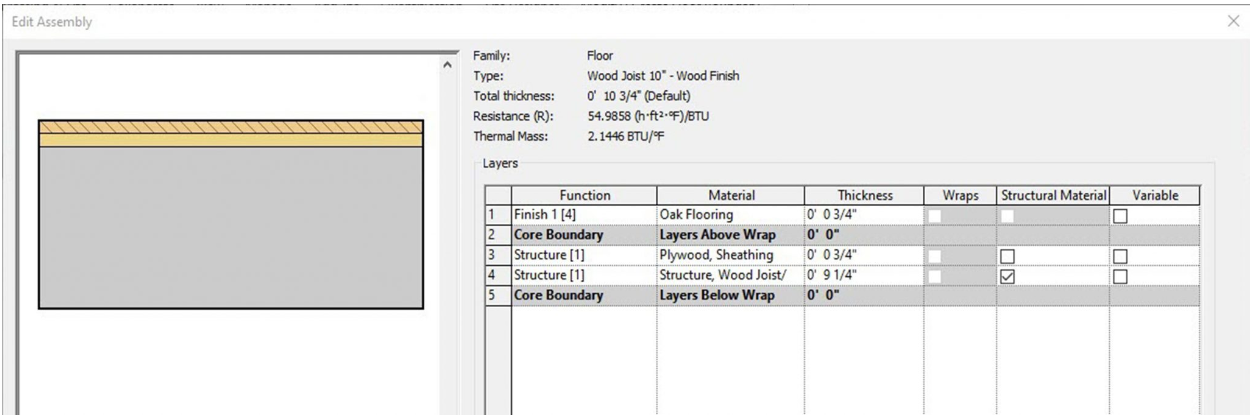
Figure 3.7 Floor Wood Joist 10” – Wood Finish
Wood Truss Joist 12” – Carpet Finish
In section, this wall follows the correct layering of materials required by code to install carpet flooring over a wooden structure. This floor system lays on top of structural wood joists that are 12” in depth.
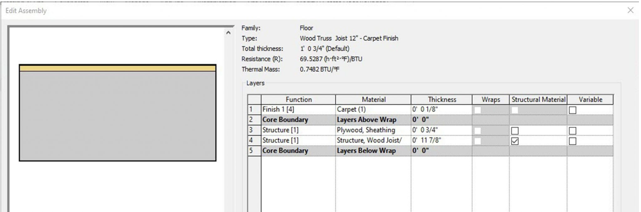
Figure 3.8 Floor Wood Truss Joist 10” – Carpet Finish
3.2 CREATE AND MODIFY FLOORS
Continue building on the project from Chapter 2: Walls, Curtain Walls, Doors, and Windows.
Create a floor using the Line tool
- Click the Architecture tab
- In the Level 1 view, click the Floor icon
 from the ribbon, under the Build panel
 - Use the Type Selector to choose the Generic – 12”
- Under the Draw panel, click the Line tool

- Draw a 20’ 0” X 80’ 0” floor as shown in Figure 3.9
- On the ribbon, click the green checkmark
 to complete the floor
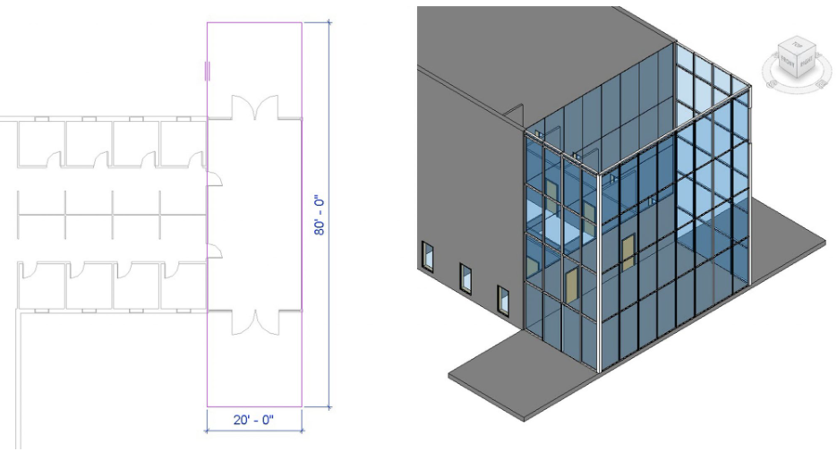
Figure 3.9 Floor shown in plan view and finished floor in 3D view
Create a floor using the Pick line tool
- Click the Architecture tab
- In the Level 1 view, click the Floor icon from the ribbon, under the Build panel
- Use the Type Selector to choose the Generic – 12”
- Under the Draw panel, click the Pick Line tool

- Hover the cursor over any wall, use the Tab key to cycle through the selection options until the centerline is highlighted with a blue line, click to select the line. Follow this step until all boundaries have been selected as shown on the left in Figure 3.10
- Click the green checkmark to complete the floor
- Select the floor
- On the ribbon, click the Copy icon

- On the ribbon, click the Paste icons
 drop-down arrow
 - Click the Aligned to Selected Levels

- The Select Levels window will open. Hold down the Control key and click levels 2, 3 and 4
- Click OK. The result is shown on the right in Figure 3.10
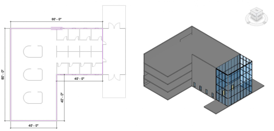
Figure 3.10 Floor shown in plan view and finished floor in 3D view
(In the 3D view two walls have been hidden to show the multiple floor plates)
Edit a floor
- Click the Architecture tab
- Open the Level 2 plan view from the Project Browser
- Select the floor
- On the ribbon, click the Edit Boundary icon

- Use the Line tool to add a 5-foot-wide mezzanine as shown in Figure 3.11
- Click the green checkmark to complete the floor
- Repeat steps 1 through 5 for Levels 3 and 4 floors.
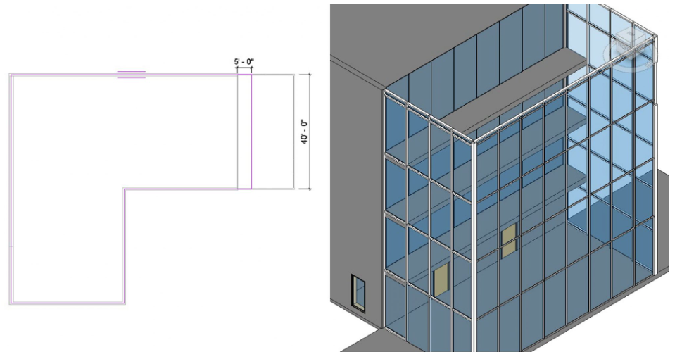
Figure 3.11 Modified floor shown in plan view and finished floor in 3D view
TIP
Create a slope using the Slope Arrow
- Click the Architecture tab
- In the Level 1 view, click the Floor icon from the ribbon, under the Build panel
- Use the Type Selector to choose the Generic – 12”
- Create a 4’ 0” X 12’ 0” floor using the line tool as shown in Figure 3.12
- Select the Slope Arrow icon
 and draw the arrow from the right to the left
 - In the Properties Palette, change the Height Offset from Level to -1’ 0”
- Click the green checkmark to complete the floor
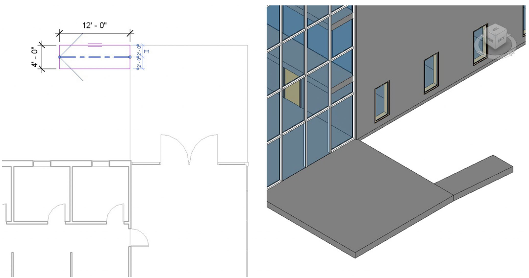
Figure 3.12 Sloped floor plan shown in plan view and 3D view
Create a slope using the Split Line tool
- Click the Architecture tab
- Select the entryway floor
- On the ribbon, click the Edit Boundary icon
- Use the Line tool and Trim tool
 to cut off a 5ft X 5ft corner from the slab as shown in Figure 3.13
 - Click the green checkmark to complete the floor
- Select the floor
- On the ribbon select the Add Split Line icon

- In the Properties Palette, change the Height Offset from Level to -1’ 0”
- Add split lines as shown in Figure 3.13
- Select the center green dashed line
- Select the witness line dimension box that appears
- Type -1’ 0”
- Press the Enter key
- Press the ESC key twice to exit the command
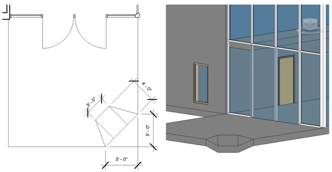
Figure 3.13 Split line slope shown in plan view and 3D view
Add an Opening By Face
- Click the Architecture tab
- In the 3D view, click the By Face icon
 on the ribbon under the Opening panel
 - Select the Level 4 floor
- Draw a 15ft X 15ft square as shown in Figure 3.14
- Use the move tool
 to center the opening as shown in Figure 3.14
 - Click the green checkmark to complete the floor
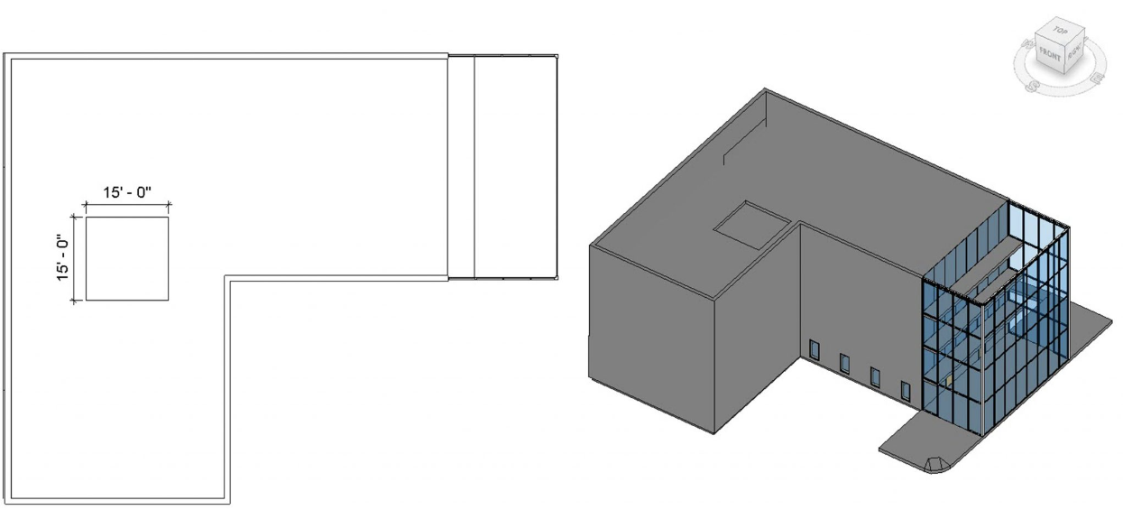
Figure 3.14 Opening by Face shown in plan view and 3D view
Add Shaft Opening
- Click the Architecture tab
- In the Level 2 view, select the Shaft icon
 on the ribbon, under the Opening panel
 - In the Properties Palette, change the following parameters
- Base Constraint: Level 2
- Base Offset: -1’ 0”
- Top Constraint: Up to Level 6
- Top Offset: 1’ 0”
- Draw a 15ft X 9ft as shown in Figure 3.15
- Click the green checkmark to complete the floor
- In the 3D view, reposition the View Cube to verify the shaft opening cuts through all 3 floors
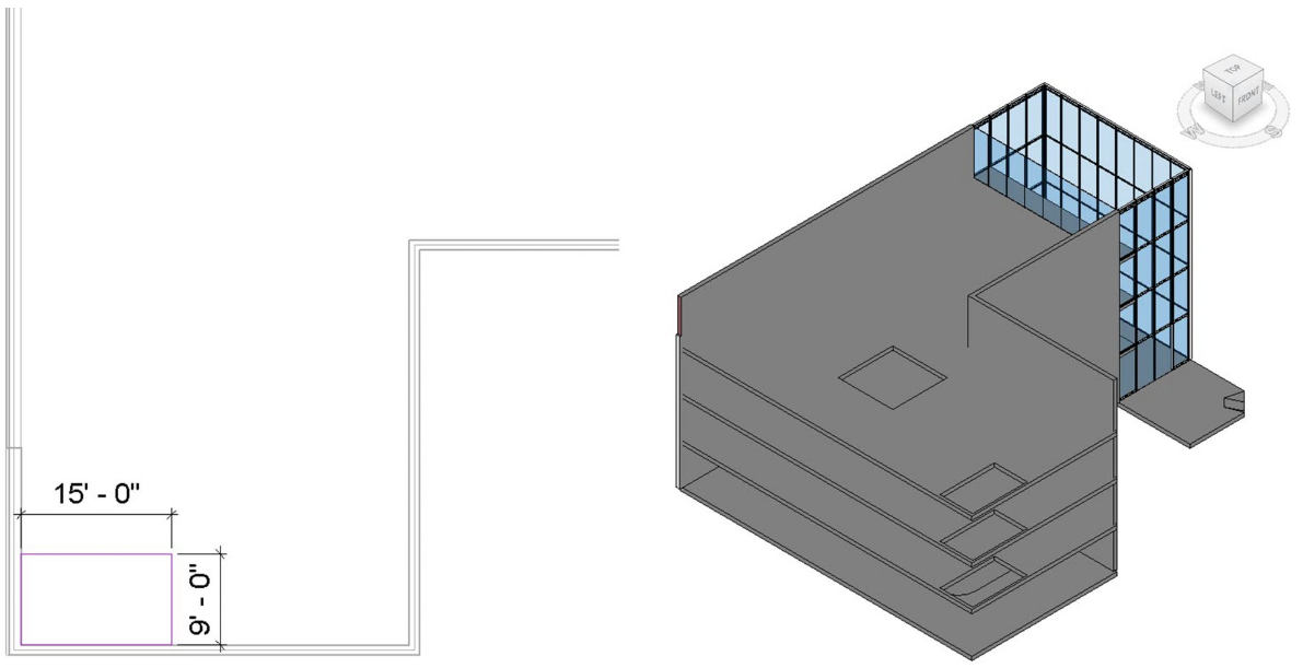
Figure 3.15 Shaft Opening shown in plan view and 3D view
(Two walls are Hidden from view to show the shaft cutting through multiple floors)
3.3 ROOFS
Basic Roofs
Generic Roofs
A Generic Roof is a blank element with no applied materials. The default sizes are 9, 12, and 18 inches thick. A material, pattern, texture, or color can be applied, and its depth altered.
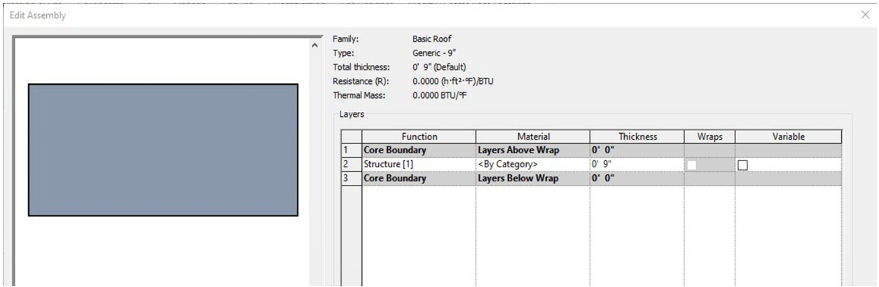
Figure 3.16 Basic Roof Generic – 9”
Generic Filled
A generic filled roof comes 12 inches thick and shows poched in section.
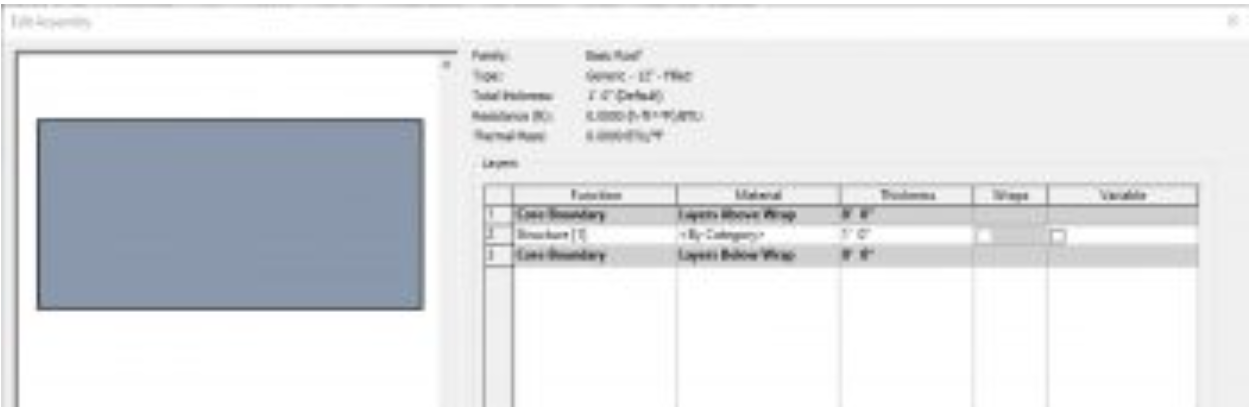
Figure 3.17 Basic Roof Generic – 12” – Filled
Detailed Roofs
Steel Truss – Insulation on Metal Deck – EPDM
In section, this roof follows the correct layering of materials required by code to install EPDM (Ethylene Propylene Diene Terpolymer) and rigid insulation over a steel structure.
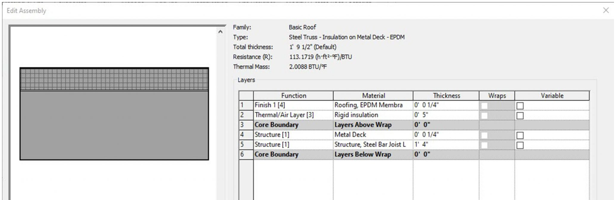
Figure 3.18 Basic Roof Steel Truss – Insulation on Metal Deck – EPDM
Wood Rafters 8” – Asphalt Shingle – Insulated
In section, this roof follows the correct layering of materials required by code to install asphalt shingles over a wooden structure.
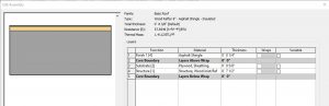
Figure 3.19 Basic Roof Wood Rafter 8” – Asphalt Shingle – Insulated
3.4 CREATE AND MODIFY ROOFS
Create a roof using the Line tool
- Open the Roof floor plan view in the Project Browser
- In the Properties Palette, under the Underlay section, change the Range: Base Level to Level 4
- Select the Roof icon
 from the Ribbon, under the Build panel
 - Use the Type Selector to choose the Generic – 12”
- Under the Draw panel, choose the Line tool or the Pick Lines tool
- On the Options Bar, change the following parameters
- Uncheck the box next to Defines Slope
- Overhang: 2’ 0”
- Draw or select lines to outline the building as shown in Figure 3.20
- Select the four walls shown in Figure 3.20 and check the box next to Defines Slope in the Properties Palette
- On the ribbon, click the green checkmark to complete the floor
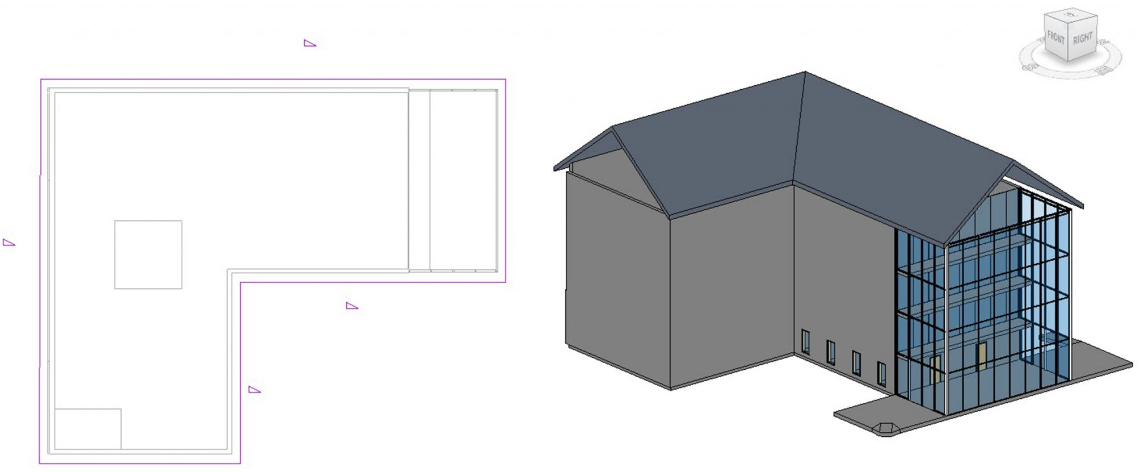
Figure 3.20 Roof outline in plan view and finished roof in 3D view
Attaching walls to a roof
- Select an exterior wall on the model
- Select the Attach Top/Base icon
 from the ribbon, under the Modify Wall panel
 - Select the Roof
- Repeat steps 1 through 3 until all the walls are attached to the roof
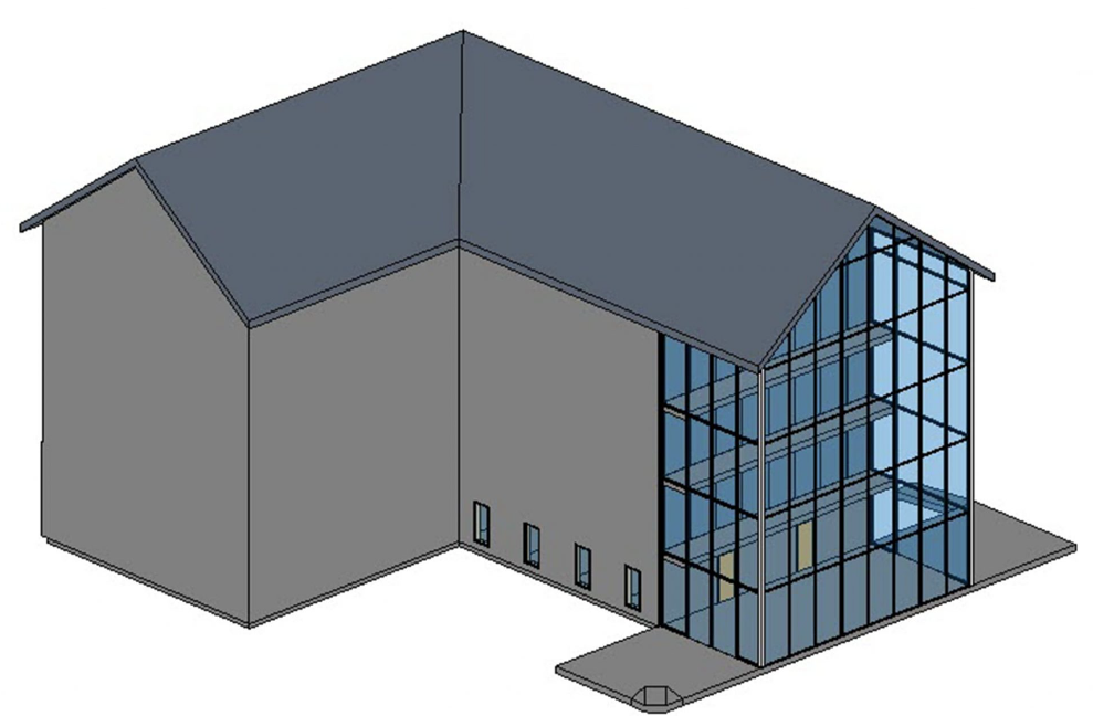
Figure 3.21 Attached walls to roof in 3D view
TIP
Editing a roof boundary
- In the Roof level, select the roof
- Select the Edit Footprint icon
- Check the box by Defines Slope for all walls in the Properties Palette as shown in Figure 3.22
- In the Properties Palette change the Slope to 6” / 12”
- Click the green checkmark to complete the Roof
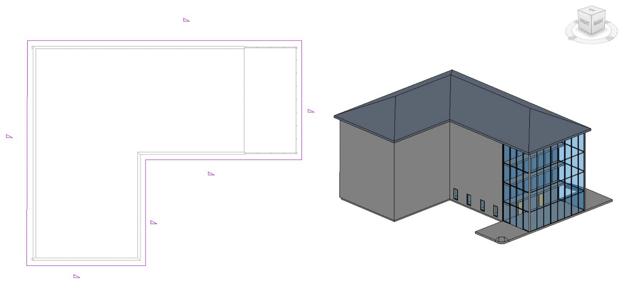
Figure 3.22 Modified roof in plan view and finished roof in 3D view
Roof by Extrusion
- In the 3D view, Click the Roof down arrow and select the Roof by Extrusion icon

- The Work Plane window will open, click the Pick a plane option
- Click OK
- Select the straight wall on the right of the curved wall as shown in Figure 3.15
- The Roof Reference Level and Offset window will open, change the following parameters
- Level: Roof
- Offset: -1’ 0”
- Click OK
- Select the Start-End-Radius Arc tool

- Hover the cursor over the top of the wall, when highlighted click to start placing an extrusion
- In the Properties Palette change the following parameters
- Extrusion Start: 2’ 0”
- Extrusion End: -10’ 0”
- Repeat Steps 1 through 8 and create two more arc extrusions
- Click the green checkmark to complete the extrusion
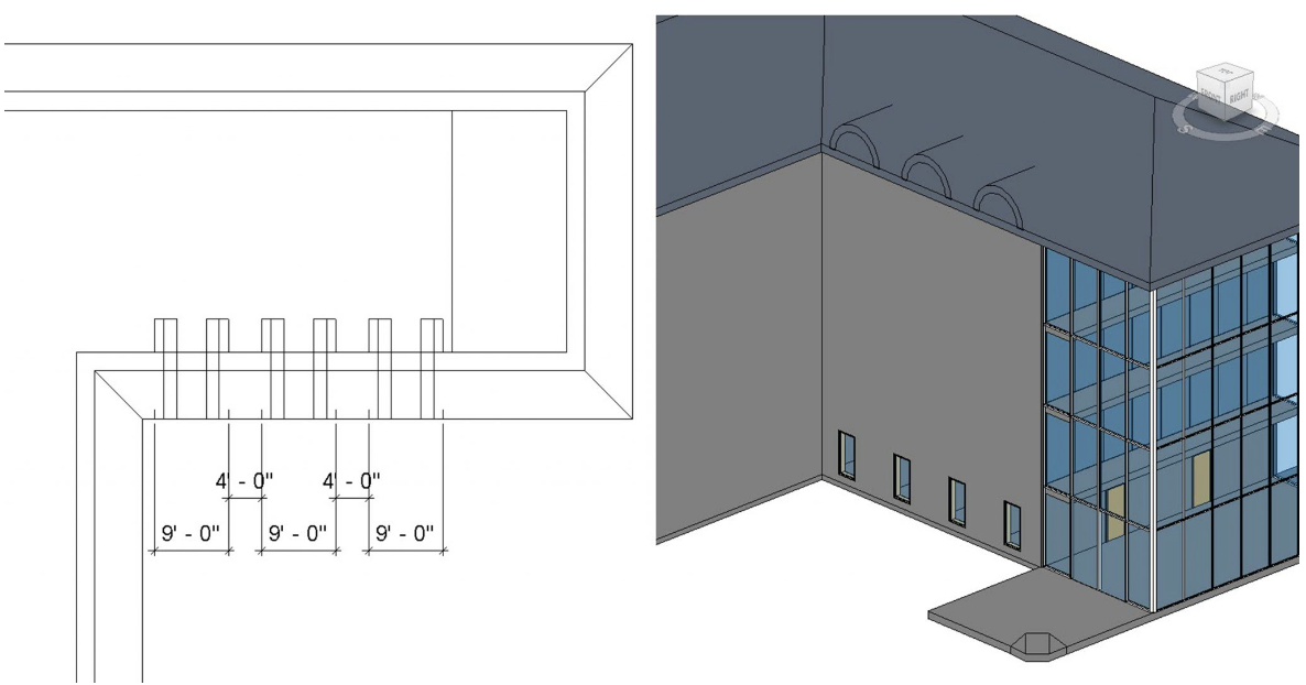
Figure 3.23 Arc roof extrusion in plan view and in 3D view
3.5 CEILINGS
Basic Ceilings
Generic Ceiling
A Generic Ceiling is a blank element with no applied materials. A material, pattern, texture, or color can be applied, and its depth altered.
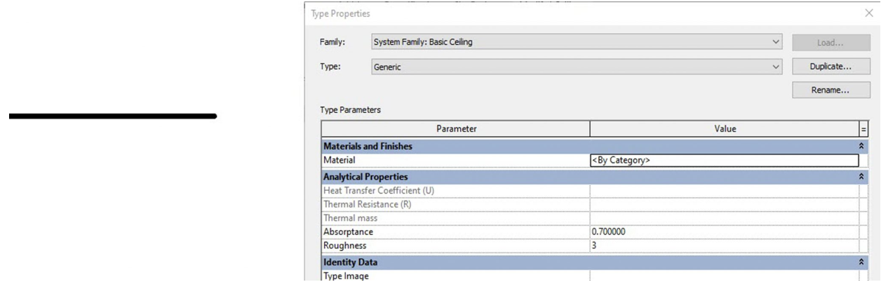
Figure 3.24 Basic Ceiling Generic
Detailed Ceilings
ACT System
In section, this ceiling follows the correct layering of materials required by code to install an Acoustic Ceiling Tile System. The tiles come 2ft X 2ft and 2ft X 4ft.
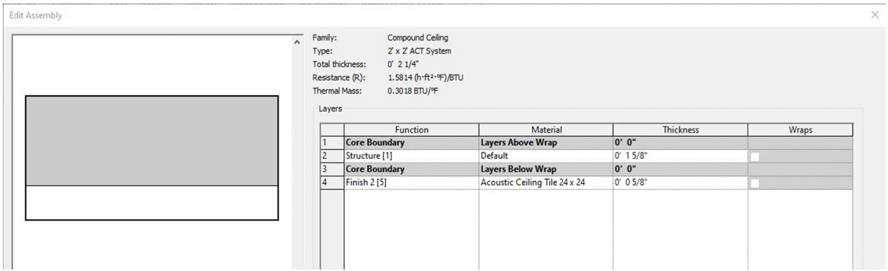
Figure 3.25 Compound Ceiling ACT system
GWB on Metal Stud
In section, this ceiling follows the correct layering of materials required by code to install the Gypsum Wall Board over a metal frame ceiling.
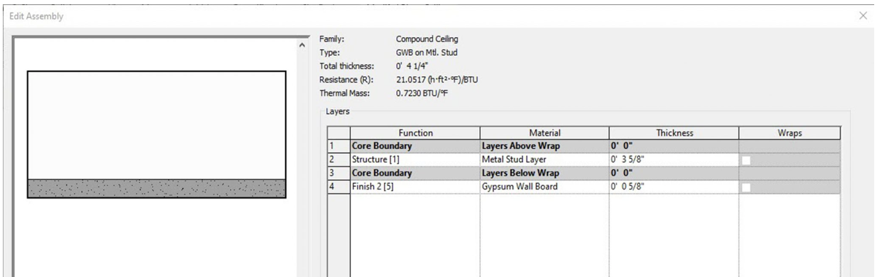
Figure 3.26 Compound Ceiling GWB on Metal Stud
3.6 CREATE AND MODIFY CEILINGS
Create a ceiling
- In the Project Browser, double-click to open the Level 1 Ceiling Plan
- Click on the Architecture tab.
- On the ribbon, under Build, select the Ceiling icon

- Use the Type Selector to choose the 2’x4’ ACT System
- On the ribbon, choose the Automatic Ceiling icon

- Hover the cursor over the main space, when the interior faces highlight red, click to apply the ceiling as shown in Figure 3.27 for reference
- Use the Type Selector to choose the 2’x2’ ACT System
- On the ribbon, choose the Sketch Ceiling icon

- Use the Line tool and draw around the interior faces of the offices as shown in 3.27 for reference
- On the ribbon, click the green checkmark to complete the ceiling
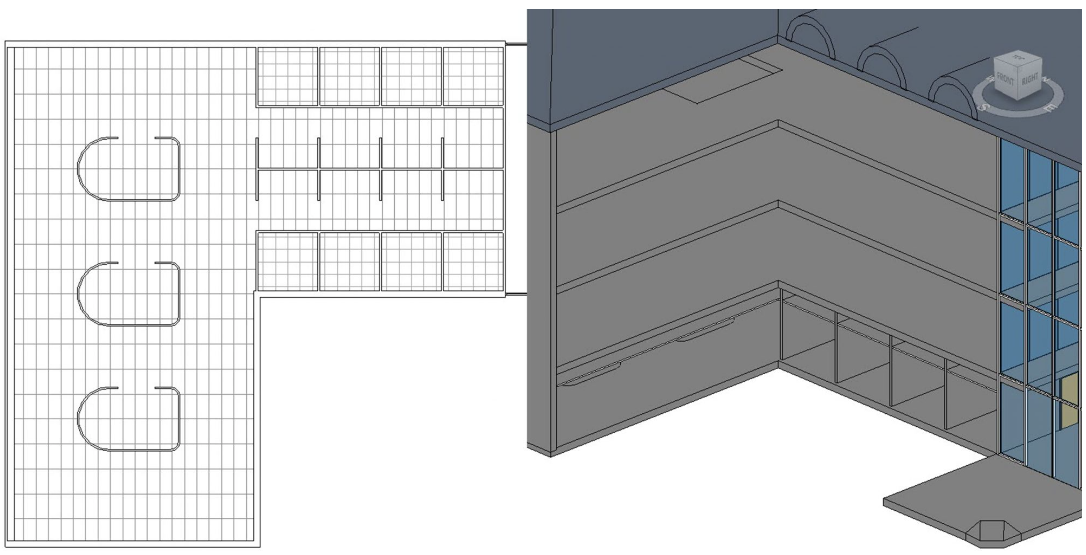
Figure 3.27 ACT Systems shown in ceiling plan and in 3D view
(In the 3D view two walls have been hidden from view to better show the ceiling system)
Edit ceiling materials
- Open the Level 4 plan view from the Project Browser
- In the Architecture tab, click the Ceiling icon
- Use the Type Selector to choose the GWB on Mtl. Stud
- In the Properties Palette, change the Height Offset from Level to 12’ 0”
- Click the Sketch Ceiling icon
- Use the Line tool and/or the Pick Lines tool to sketch the ceiling plan in Figure 3.29
- In the Properties Palette, click the Edit Type button

- The Type Properties window will open, click the Duplicate button
- Accept the default name ‘GWB on Mtl. Stud 2’ by clicking OK
- Click the Edit button next to Structure
- On the 4th line, next to Gypsum Wall Board select the square box with 3 dots

- The Material Browser window will open, Click the Add Materials button
 and click the Duplicate Selected Material option
 - Rename the material ‘Gypsum Pattern’
- Under the Graphics tab, find the Surface Pattern section
- In the subsection labeled Foreground, click the white box next to the pattern labeled <none>
- Scroll through the list of patterns and choose Sand – Dense
- Click OK to close all 4 windows
- On the ribbon, click the green checkmark to complete the ceiling
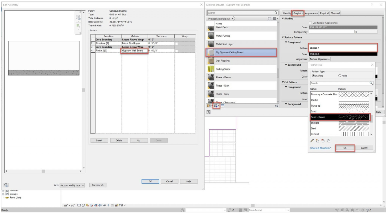
Figure 3.28 Adjusting the ceiling material properties
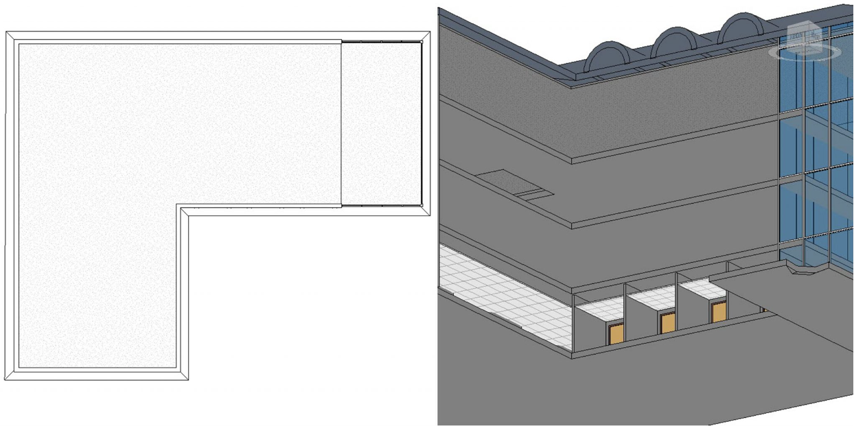
Figure 3.29 View of Level 4 ceiling in plan view and a 3D view looking from the bottom to the top
(In the 3D view two walls have been hidden from view to better show the ceiling system)
TIP