
5: Adding - Modifying Families
- Page ID
- 88765

Families are typically small-scale elements where most files are set with given parameters. Parameters are used to define the extent of an element. For example, a family of windows may have parameters that define the sizes available per a manufacturer’s catalog such as 2ft X 2ft, 2ft X 4ft, 3ft X 4ft, and 3ft X 5ft.
Revit provides several generic families of doors, windows, casework, furniture, and more. A user can easily create custom families or downloaded files from the internet.
A custom family file uses templates to define an elements category. Once a template is chosen it cannot be changed later. The file will have to be recreated in a new template because the copy-paste function does not work between families.
Element-based – A family created using an element-based template such as “floor-based” or “wall-based” can only be placed on that element within a project.
Adaptive – A family created where the parameters are much more flexible and can conform to any project’s unique geometries, however, the 2D annotation options are disabled (Text, symbols, detail components, etc).
5.1 PLACE FAMILY ELEMENTS
Through the Project Browser
Refer to Chapter 1, section 1.4 on Project Browser, Place family elements
Through the Ribbon
- Click the Architecture ta
- Click the Component icon

- Click Place a Component
- On the ribbon, click the Load Family icon

- The Load Family window will appear, open the Furniture folder
- Open the Seating folder
- Choose the Sofa-Corbu
- Click Open
- Click the canvas to place the sofa
- Explore the folders and place a few more elements
- Use the Type Selector to choose a different element such as the Desk.
- Save and close this project
TIP
5.2 CREATE A FAMILY FROM TEMPLATE
Create a Profile file
- Click the File tab
- Click the side arrow to access the New sub-menu
- Choose to begin a new Family
- In the New Family – Template File, choose the Profile.RFT file
- Click the File tab
- Click the Save As option
- Choose to save as a Family
- Save in a folder that is memorable
- Name the family “Elaborate Table Leg Profile”
- In the Draw panel, use the Line tool
 and Start-End-Radius arc tool
  to draw the profile shown in Figure 5.1
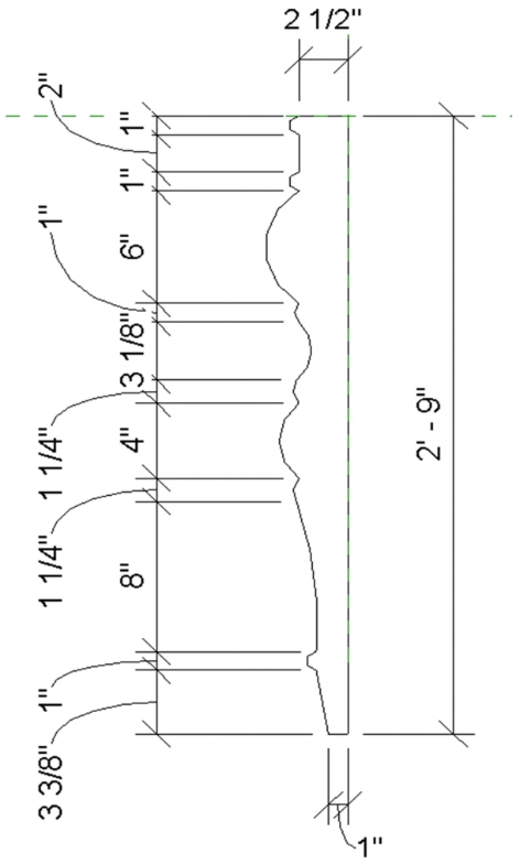
Figure 5.1 Profile shape and dimensions in 2D
Open a Family Template
- Click the File tab
- Click the side arrow to access the New sub-menu
- Choose to begin a new Family
- In the New Family – Template File, choose the Furniture.RFT file
- Click the File tab
- Click the Save As option
- Choose to save as a Family
- Save in a folder that is memorable
- Name the family “Elaborate Dining Table”
5.3 ADD REFERENCE PLANES AND SET PARAMETERS
Reference planes have two uses: one is used as guidelines or constructions to align elements to a specific position and the second use is to control the form or position of geometries. Constraints are used on geometries to bound them to reference planes, selected dimensions, or alignments.
In this example the tables’ geometries will be aligned to placed reference planes then constraints are set to lock the table’s dimensions to set sizes.
Placing Reference Planes
- First, set up the user interface to view all 4 windows, In the View tab, click the Tile Views icon

- In the Ref. Level view, go to the Create tab on the Ribbon then click on the Reference Plane icon

- Draw a vertical line on one side of the center reference plane and use the Mirror icon
 to create another
 - Select each reference plane and rename them Left and Right respectively
- Use the witness lines to change the distance to the center reference plane to 3’0” as shown in Figure
5.2
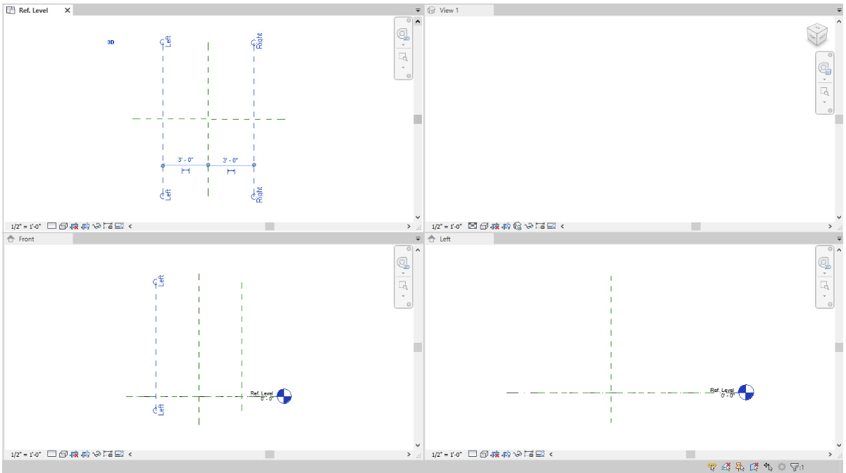
Figure 5.2 Vertical reference planes created and labeled - Create one horizontal line on the left side of the center reference plane then use the Mirror icon to create another
- Label them Top and Bottom respectively
- Use the witness lines to change the distance to the center reference plane to 1’6” as shown in Figure 5.3
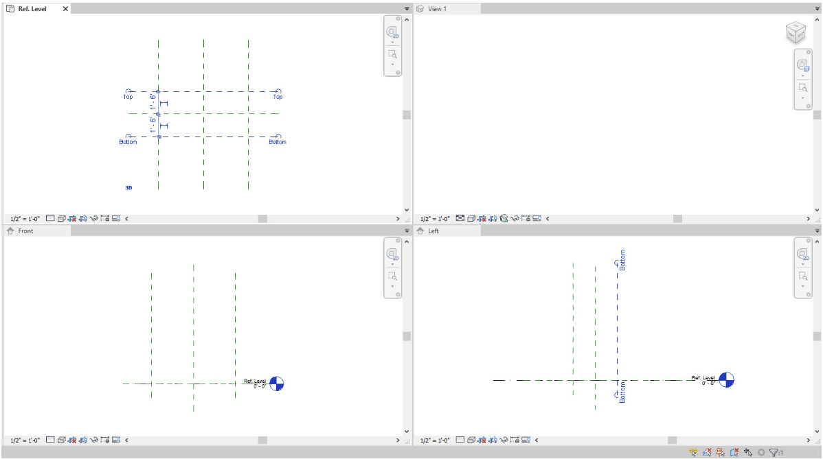
Figure 5.3 Horizontal reference planes created and labeledSetting Constraints
- Under the Modify tab, use the Aligned Dimension icon to place dimension strings connecting the Left-Center-Right and another connecting Left-Right as shown in Figure 5.4 (left). Do the same for Top-Center-Bottom and Top-Bottom as shown in Figure 5.4 (left)
- Select the 3’ 0” dimension string and enable equal dimensions by clicking on the EQ as shown in Figure 5.4 (right). Do the same for the 1’ 6” dimension string.
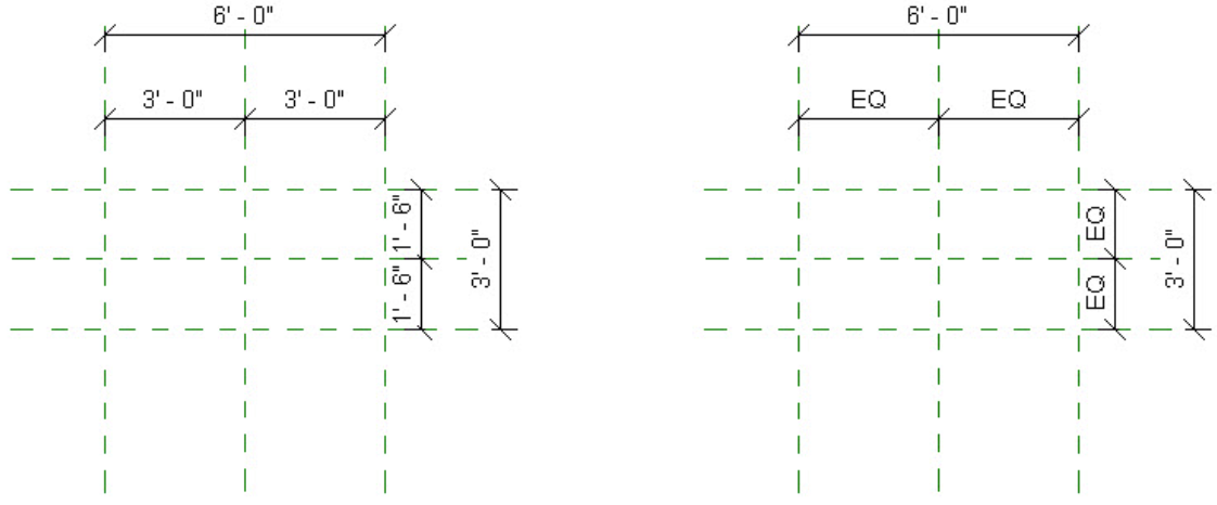
Figure 5.4 (left) Dimension strings placed and (right) enabled EQ for 3’0” and 1’6” dimension strings - Select the 6’0″ dimension string
- On the Ribbon under the Architecture tab, click the Create Parameter icon

- In the Parameter Properties window change the following information
- Name the parameter Length
- Select the Type option
- Click on the Edit Tooltip and add a description
- Click OK
- Complete the same instructions for the 3-foot dimension
Flexing Constraints
“Flexing” constraints are used to test if the dimension strings act accordingly to the applied changes. To flex a model, the Family Type icon is used. For this example, assume the manufacturer of the dining table wants to offer three lengths for different household sizes. The 6-foot table sits 4 people, the 7-ft table sits 6 people, and the 8-ft table sits 8 people.
- On the ribbon, click the Family Type icon
 to flex the model.
 - Change the Length to 7 feet and click Apply. If the reference planes are set correctly the model will reflect the changed length in the Ref. Level view.
- Change the Length back to 6 feet
Creating New Parameters
The New Parameter icon is used to create the available lengths of tables offered by the manufacturer. The table geometries will respond to the new parameters. When a Revit user uploads this table family into a project, they can choose which length of the table is appropriate for their client.
- In the Family Type window click the New Parameter icon

- Name the type 6-foot table and click OK
- Click Apply
- Use the New Type icon to create a 7-foot and click OK
- Change the length to 7’0”
- Click Apply
- Click the New Type icon and create an 8-foot table
- Change the Type to 6 feet and click OK to close to the Family Type window
- In the Front view, create the following reference planes that will determine the top and bottom of the tabletop height then rename them accordingly
- Top of Table at 3’ 0”
- Bottom of Table at 2’ 9”
- Lock both lines using the Pin Tool

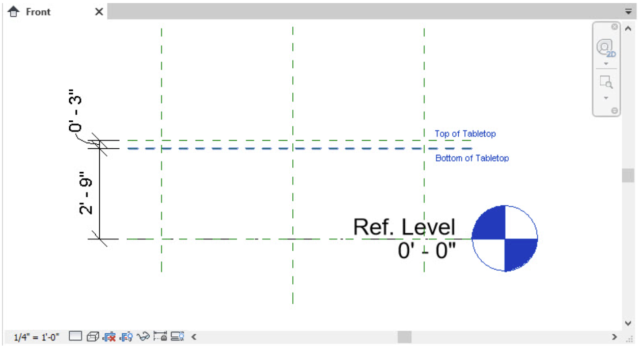
Figure 5.5 Reference planes drawn in the Front view
5.4 CREATE A SOLID FORM
- In the Front view under the Create tab, click the Set icon
 on the Ribbon
 - Select the Name option
- In the drop-down menu choose Reference Plane: Bottom of Table and select OK
- Under the Create tab, click the Extrusion icon

- In the Properties Palette, change the following parameters
- Extrusion End: 0’ 3”
- Extrusion Start: 0’ 0”
- Use the Rectangle tool to draw a 3’X6’ extrusion along the reference planes
- Click the green
 checkmark to complete the extrusion
 - To lock the rectangle geometry to the reference plane go to the Modify tab and select the Align tool
- In the Ref. Level view, select the top edge of the table
- Then select the reference plane that the edge lies on.
- An open lock will appear, click on it to lock the edge of the table to that reference plane.
- Do this to each edge of the tabletop rectangle.
- In View 1, on the View Control Bar, use the Visual Style icon to choose the Shaded
 selection
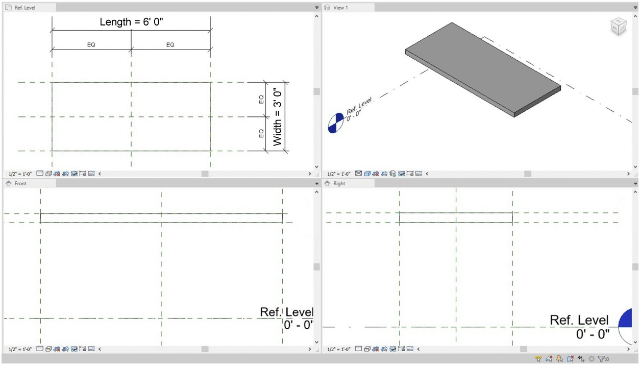
Figure 5.6 Tabletop solid extrusion
Create a Sweep Form by Load Profile
- Create a second set of reference lines following Figure 5.7
- Label the line like the following respectively
- Top 1, Top 2, Bottom 1, Bottom 2, Left 1, Left 2, Right 1, and Right 2.
- Under the Modify tab, use the Aligned Dimensions icon
 to add dimensions as shown in Figure 5.7
 - Select each of the highlighted dimensions individually (as shown in Figure 5.7) and click the unlock symbol to Lock it

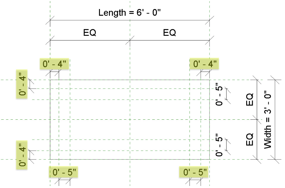
Figure 5.7 Highlighted dimensions shown are locked - Under the Create tab, click the Sweep icon

- Click the Sketch Path icon

- Use the circle tool
 to create a circle with a 1/4” radius in between the two 5″ reference lines in the top right corner of the tabletop
 - Click the green checkmark to complete the path
- On the Ribbon under the Modify tab, click Load Profile

- Navigate to select the Table Leg Profile created previously
- Click Open
- On the Ribbon in the Sweep panel, use the drop-down menu by Profile to choose the Table Leg Profile.
- Click the green checkmark to complete the Profile
TIP
If the profile will not complete due to an error, use trim/extend tool
 to connect the lines so geometries do not fold in on itself
Edit Work Plane if the leg is not in the right place
- Select the Leg
- Use the Mirror – Pick Axis tool to create a second leg
- Select the two first legs
- Use the Mirror – Pick Axis tool to create the last two legs
- Check the Flex using the Family Types icon
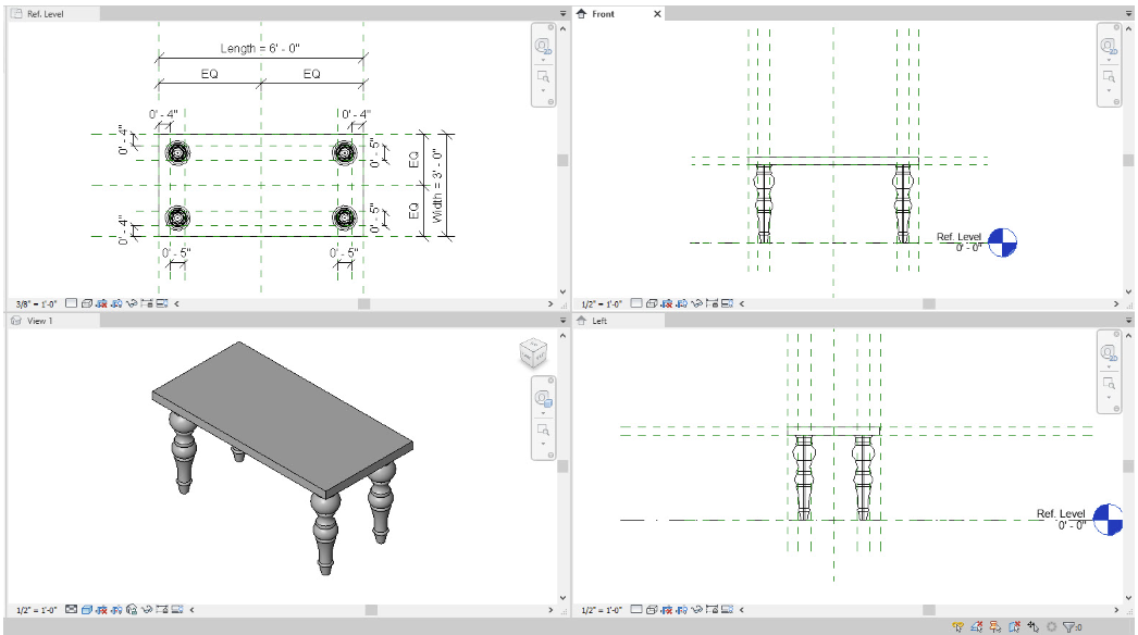
Figure 5.8 Table leg profile sweep applied and mirrored
Create a Sweep Form by Sketch
- Under the Create tab, click the Set icon on the Ribbon
- Select the Name option
- Choose Reference Plane: Top of Table then select OK
- Under the Create tab, click the Sweep icon
- Click the Sketch Path icon
- In the Ref. Level view, use the rectangle tool
 to outline the table
 - Click the green checkmark to complete the path
- On the ribbon, click the Select Profile

- Click the Edit Profile icon

- In the Right view, draw the profile like the one shown in Figure 5.9
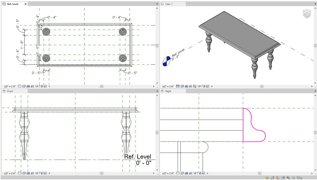
Figure 5.9 Table edge sketch sweep
5.5 CREATE A VOID FORM EXTRUSION
- Use the Set icon to choose the Reference Plane: Top of Table
- In the Reference Level view, go to the Create tab
- Click the Void forms drop-down menu then click the Void Extrusion icon

- On the Options Bar, change the depth to 1″ and the offset to 2”
- Select the Pick Line tool
 from the Draw panel
 - Hover the cursor over the reference lines at the edge of the tabletop until the light blue dashed line appears facing towards the tabletop’s interior. Use Figure 5.10 as a reference. Do this for all 4 edges.
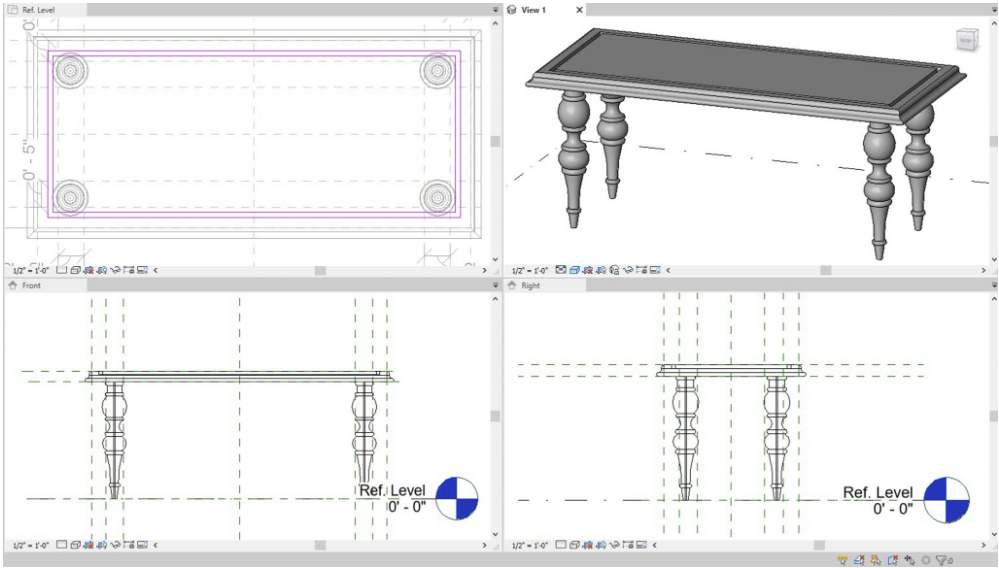
Figure 5.10 Reveal created using a void extrusion - Use the Trim/Extend tool to trim the rectangle
- Use the Offset tool
 at 1” to create a second rectangle within the first
 - Use the Trim/Extend tool to trim the second rectangle
- Click the green checkmark to complete the void extrusion
- Select the void
- In the Properties Palette, change the Extrusion Start to -0’ 1”
- Click Apply
TIP
5.6 MATERIALS
Create a new Material using the Asset Library
- In the 3D view, select the first tabletop extrusion
- In the Properties Palette, next to Material, click the 3 dots button

- Select the Default material
- Click the Materials Icon

- Click the Duplicate Selected Material
- Change the name to Wooden Finish
- With the Wooden Finish selected, click the Asset Library icon

- In the Asset Browser, expand Appearance Library
- Click Wood
- Use the search bar or scroll down to find Mahogany – Stained Dark Polished
- Use the Replace Asset icon
 to apply the material
 - Click the Asset Library icon again to close the Asset Browser window
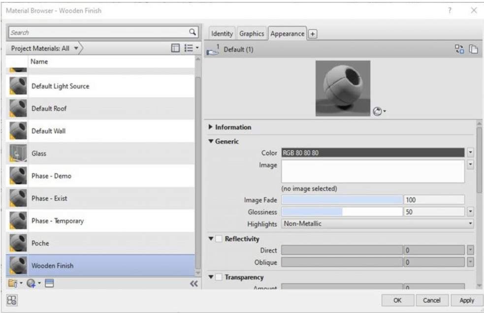
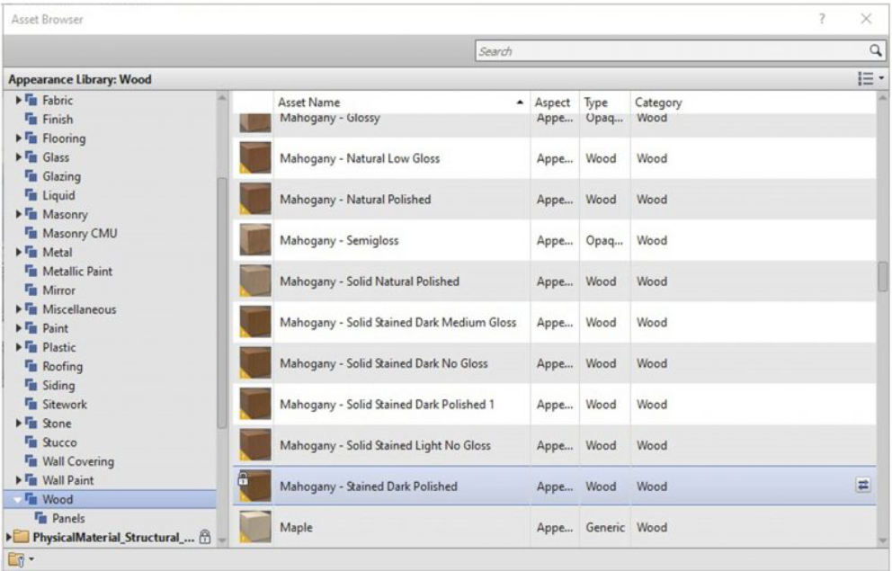
Figure 5.11 Material and Asset Browser window - Click the Image box
- In the Texture Editor, change the Rotation to 90 degrees
- Click Done to accept the changes
- Click Apply and OK in the Material Browser window
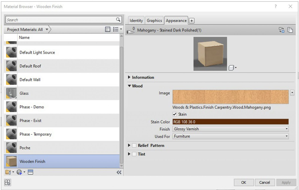
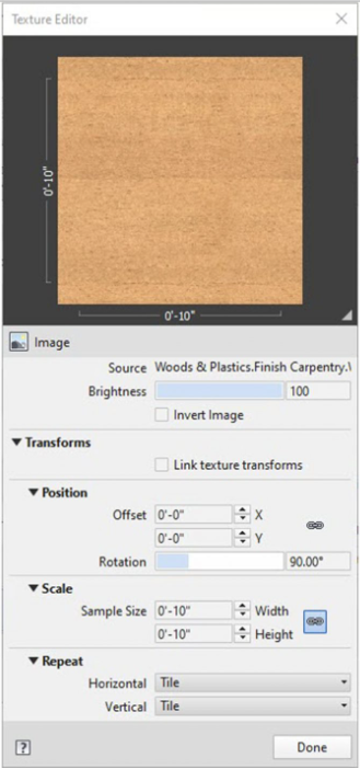
Figure 5.12 Material Browser and Texture Editor windows - In the 3D view, use the Visual Style icon to change the appearance to Realistic

- Follow the same steps to apply the Mahogany – Stained Dark Polished material to the rest of the table elements
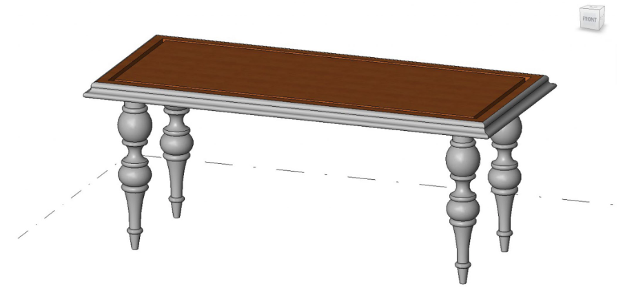
Figure 5.13 Mahogany material applied to the tabletop extrusion
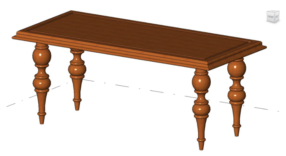
Figure 5.14 Completed table with Mahogany material applied to all elements
5.7 Nested Family
- Start a New Family using the Generic Model template
- Follow Figure 5.11 to create an 8” X 16” oval plate and an apple using the spline tool

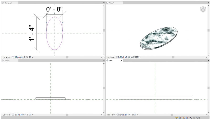
Figure 5.15 Solid extrusion with an applied marble material - Change the Material to a Stone Marble finish
- Follow Figure 5.16 to create an apple on top of the marble Plate
- Use the Red Paint from the Asset Library
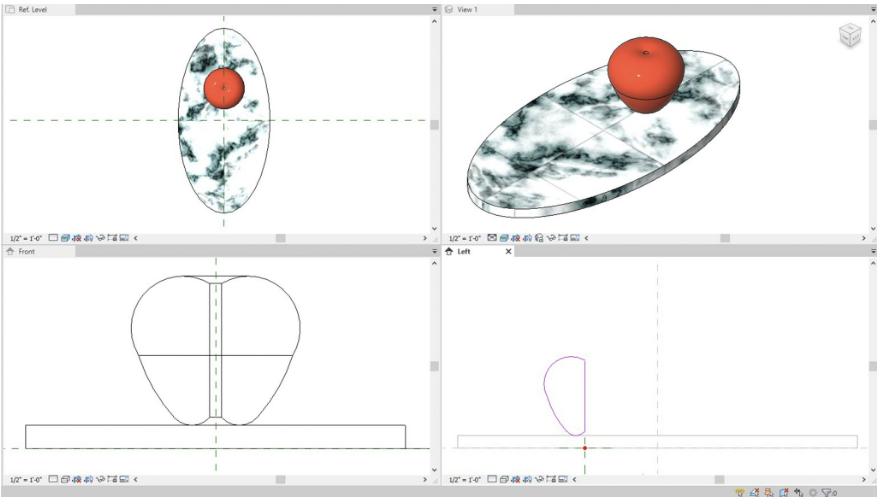
Figure 5.16 Sweep extrusion – apple - Go to File and Save As a family
- Label the project Table Decoration
TIP
- In the Table Decoration project, click the Load into Project icon
 under the Create tab
 - Deselect the Project file and select the Dining Table file
- Click OK
- Close the Table Decoration windows
- In the Ref. View of the Dining Table project, click the Create tab
- Click the Component icon
- Use the Type Selector to choose the Table Decoration
- In the Properties Palette change the Offset to 3’0”
- Click to place the decoration on the table
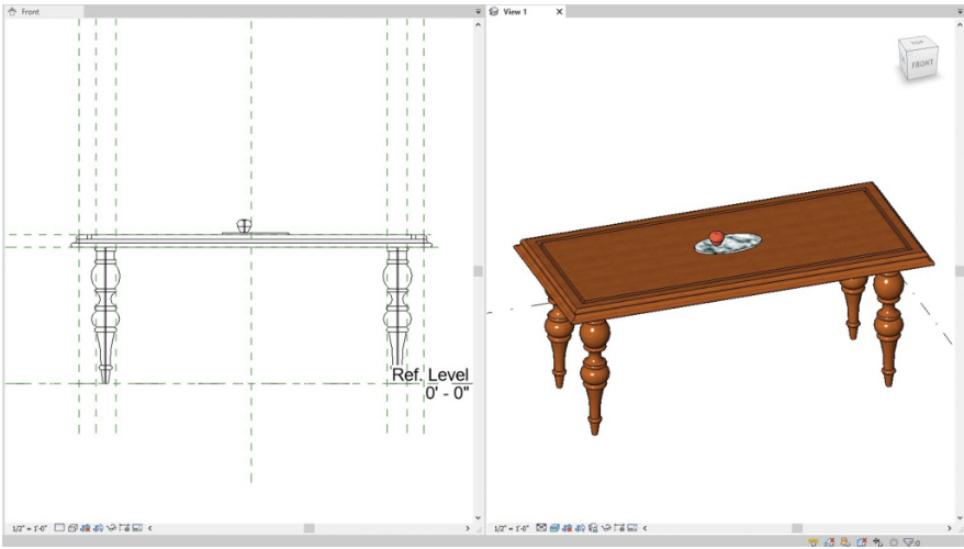
Figure 5.17 Table Decoration is Nested within the Dining Table file - Load Family into a Project
- In the Dining Table project, click the View tab
- Click the Load into Project icon
- Place an 8-foot, 7-foot, and 6-foot table on the second floor of the building
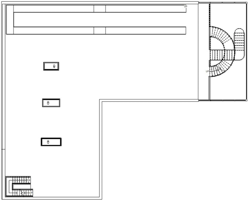
Figure 5.18 Placed Elaborate table families