
6: Massing - Conceptual Mass
- Page ID
- 88766

\( \newcommand{\vecs}[1]{\overset { \scriptstyle \rightharpoonup} {\mathbf{#1}} } \)
\( \newcommand{\vecd}[1]{\overset{-\!-\!\rightharpoonup}{\vphantom{a}\smash {#1}}} \)
\( \newcommand{\dsum}{\displaystyle\sum\limits} \)
\( \newcommand{\dint}{\displaystyle\int\limits} \)
\( \newcommand{\dlim}{\displaystyle\lim\limits} \)
\( \newcommand{\id}{\mathrm{id}}\) \( \newcommand{\Span}{\mathrm{span}}\)
( \newcommand{\kernel}{\mathrm{null}\,}\) \( \newcommand{\range}{\mathrm{range}\,}\)
\( \newcommand{\RealPart}{\mathrm{Re}}\) \( \newcommand{\ImaginaryPart}{\mathrm{Im}}\)
\( \newcommand{\Argument}{\mathrm{Arg}}\) \( \newcommand{\norm}[1]{\| #1 \|}\)
\( \newcommand{\inner}[2]{\langle #1, #2 \rangle}\)
\( \newcommand{\Span}{\mathrm{span}}\)
\( \newcommand{\id}{\mathrm{id}}\)
\( \newcommand{\Span}{\mathrm{span}}\)
\( \newcommand{\kernel}{\mathrm{null}\,}\)
\( \newcommand{\range}{\mathrm{range}\,}\)
\( \newcommand{\RealPart}{\mathrm{Re}}\)
\( \newcommand{\ImaginaryPart}{\mathrm{Im}}\)
\( \newcommand{\Argument}{\mathrm{Arg}}\)
\( \newcommand{\norm}[1]{\| #1 \|}\)
\( \newcommand{\inner}[2]{\langle #1, #2 \rangle}\)
\( \newcommand{\Span}{\mathrm{span}}\) \( \newcommand{\AA}{\unicode[.8,0]{x212B}}\)
\( \newcommand{\vectorA}[1]{\vec{#1}} % arrow\)
\( \newcommand{\vectorAt}[1]{\vec{\text{#1}}} % arrow\)
\( \newcommand{\vectorB}[1]{\overset { \scriptstyle \rightharpoonup} {\mathbf{#1}} } \)
\( \newcommand{\vectorC}[1]{\textbf{#1}} \)
\( \newcommand{\vectorD}[1]{\overrightarrow{#1}} \)
\( \newcommand{\vectorDt}[1]{\overrightarrow{\text{#1}}} \)
\( \newcommand{\vectE}[1]{\overset{-\!-\!\rightharpoonup}{\vphantom{a}\smash{\mathbf {#1}}}} \)
\( \newcommand{\vecs}[1]{\overset { \scriptstyle \rightharpoonup} {\mathbf{#1}} } \)
\(\newcommand{\longvect}{\overrightarrow}\)
\( \newcommand{\vecd}[1]{\overset{-\!-\!\rightharpoonup}{\vphantom{a}\smash {#1}}} \)
\(\newcommand{\avec}{\mathbf a}\) \(\newcommand{\bvec}{\mathbf b}\) \(\newcommand{\cvec}{\mathbf c}\) \(\newcommand{\dvec}{\mathbf d}\) \(\newcommand{\dtil}{\widetilde{\mathbf d}}\) \(\newcommand{\evec}{\mathbf e}\) \(\newcommand{\fvec}{\mathbf f}\) \(\newcommand{\nvec}{\mathbf n}\) \(\newcommand{\pvec}{\mathbf p}\) \(\newcommand{\qvec}{\mathbf q}\) \(\newcommand{\svec}{\mathbf s}\) \(\newcommand{\tvec}{\mathbf t}\) \(\newcommand{\uvec}{\mathbf u}\) \(\newcommand{\vvec}{\mathbf v}\) \(\newcommand{\wvec}{\mathbf w}\) \(\newcommand{\xvec}{\mathbf x}\) \(\newcommand{\yvec}{\mathbf y}\) \(\newcommand{\zvec}{\mathbf z}\) \(\newcommand{\rvec}{\mathbf r}\) \(\newcommand{\mvec}{\mathbf m}\) \(\newcommand{\zerovec}{\mathbf 0}\) \(\newcommand{\onevec}{\mathbf 1}\) \(\newcommand{\real}{\mathbb R}\) \(\newcommand{\twovec}[2]{\left[\begin{array}{r}#1 \\ #2 \end{array}\right]}\) \(\newcommand{\ctwovec}[2]{\left[\begin{array}{c}#1 \\ #2 \end{array}\right]}\) \(\newcommand{\threevec}[3]{\left[\begin{array}{r}#1 \\ #2 \\ #3 \end{array}\right]}\) \(\newcommand{\cthreevec}[3]{\left[\begin{array}{c}#1 \\ #2 \\ #3 \end{array}\right]}\) \(\newcommand{\fourvec}[4]{\left[\begin{array}{r}#1 \\ #2 \\ #3 \\ #4 \end{array}\right]}\) \(\newcommand{\cfourvec}[4]{\left[\begin{array}{c}#1 \\ #2 \\ #3 \\ #4 \end{array}\right]}\) \(\newcommand{\fivevec}[5]{\left[\begin{array}{r}#1 \\ #2 \\ #3 \\ #4 \\ #5 \\ \end{array}\right]}\) \(\newcommand{\cfivevec}[5]{\left[\begin{array}{c}#1 \\ #2 \\ #3 \\ #4 \\ #5 \\ \end{array}\right]}\) \(\newcommand{\mattwo}[4]{\left[\begin{array}{rr}#1 \amp #2 \\ #3 \amp #4 \\ \end{array}\right]}\) \(\newcommand{\laspan}[1]{\text{Span}\{#1\}}\) \(\newcommand{\bcal}{\cal B}\) \(\newcommand{\ccal}{\cal C}\) \(\newcommand{\scal}{\cal S}\) \(\newcommand{\wcal}{\cal W}\) \(\newcommand{\ecal}{\cal E}\) \(\newcommand{\coords}[2]{\left\{#1\right\}_{#2}}\) \(\newcommand{\gray}[1]{\color{gray}{#1}}\) \(\newcommand{\lgray}[1]{\color{lightgray}{#1}}\) \(\newcommand{\rank}{\operatorname{rank}}\) \(\newcommand{\row}{\text{Row}}\) \(\newcommand{\col}{\text{Col}}\) \(\renewcommand{\row}{\text{Row}}\) \(\newcommand{\nul}{\text{Nul}}\) \(\newcommand{\var}{\text{Var}}\) \(\newcommand{\corr}{\text{corr}}\) \(\newcommand{\len}[1]{\left|#1\right|}\) \(\newcommand{\bbar}{\overline{\bvec}}\) \(\newcommand{\bhat}{\widehat{\bvec}}\) \(\newcommand{\bperp}{\bvec^\perp}\) \(\newcommand{\xhat}{\widehat{\xvec}}\) \(\newcommand{\vhat}{\widehat{\vvec}}\) \(\newcommand{\uhat}{\widehat{\uvec}}\) \(\newcommand{\what}{\widehat{\wvec}}\) \(\newcommand{\Sighat}{\widehat{\Sigma}}\) \(\newcommand{\lt}{<}\) \(\newcommand{\gt}{>}\) \(\newcommand{\amp}{&}\) \(\definecolor{fillinmathshade}{gray}{0.9}\)Massing can be used to build anything from small elements to an entire building’s masses. In this chapter, start a new project using the Architectural template. Save the new project as “Class Project 2”.
6.1 TYPES OF MASSING
In-Place Mass
An In-Place Mass is located on the ribbon under the Massing & Site tab by selecting the In-Place Mass icon. This massing is used to create large-scale building masses where floors, walls and roofs can be added quickly. The items created in a project through this method are only available in this project and will not be saved as an individual family file.
Model In-Place
The model in-place is located on the ribbon under the Architecture tab by accessing the Component icons drop-down menu. This massing is used to build a small-scale element that is specific to the project such as countertops shapes, wall details, or shading systems, where the project’s geometries are available to build from. The items created in a project through this method are only available in this project and will not be saved as an individual family file.
Conceptual Mass
A conceptual mass can be created by navigating through the File tab, New sub-menu, and selecting Conceptual Mass. When working in a conceptual mass file, the project does not contain other project geometries to work from. A Conceptual Mass file is different than a Family file because massing can be quickly modeled, there is not a list of categorized model types to choose from and it is typically used for large-scale massing. This massing is saved as separate files and can be loaded into any project.
6.2 CREATE IN-PLACE MASS
- Open a New, Architectural template project
- Save the project as “Class Project 2”
- Open the 3D view by clicking the Default 3D View

- Open the North Elevation from the Product Browser
- On the ribbon, under the Architecture tab, click the Level Icon

- Place 3 levels at 20ft, 30ft, 40ft, and 50ft from the ground plane
- Close the North Elevation
- Under the View tab, click the Tile Views icon

- Click the Massing & Site tab
- Click the In-Place Mass icon

- Name the mass Main Building
- Click OK
- On the ribbon, click the Model icon

- Use the Line tool
 to draw a 60ft X 60ft square as shown in Figure 6.1
 - Select the square
- On the ribbon, click the Create Forms
 drop-down menu and choose the Solid Form
  option
 - In the 3D view, select the top face of the cube and use the witness lines to adjust the height to 20’0” as shown in Figure 6.1
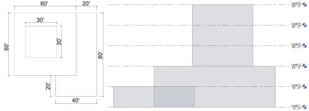
Figure 6.1 Massing dimensions shown in the Level 5 plan and the North elevation view - Repeat steps 13 through 16 until all three masses have been created as shown in Figure 6.2
- Click the green
 checkmark to finish the mass
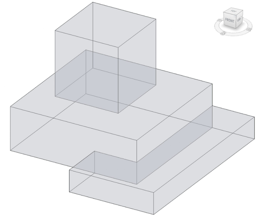
Figure 6.2 Completed massing shown in 3D view
TIP
Apply Floors, Walls, and a Roof by Face to an In-Place mass
- In the 3D view, select the mass
- On the ribbon, click Mass floors

- In the window click to check the box next to Level 1, 2, 3, 4, and 5.
- Click to open the architecture tab
- Click the Floor icon
 drop-down menu and click the Floor by face option
 - Use the Type Selector to change the type to 3” LW Concrete on 2” Metal Deck
- Click on each floor plane which will turn blue after selected
- On the ribbon, click the Create Floor
 Icon
Icon
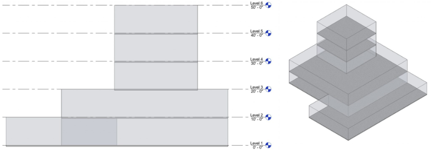
Figure 6.3 Created floors shown in the North elevation and in 3D view - On the Architecture tab, click the Wall icon
 drop-down menu to choose the Wall By Face
  option
 - Use the Type Selector to change the type to Exterior – EIFS on Metal stud
- As each wall is selected in the 3D view, the plane becomes a thickened wall
- Click the Modify icon
 to exit the command
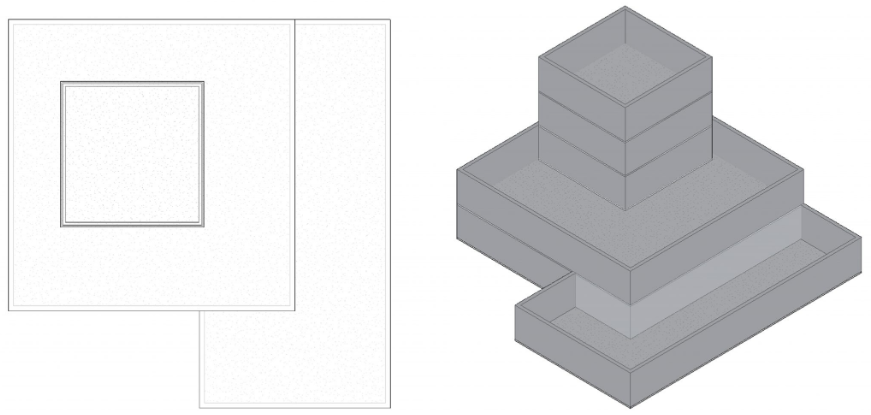
Figure 6.4 Created walls shown in the Level 5 plan view and 3D view - On the Architecture tab, click the Roof icon
 drop-down menu to choose the Roof by Face
  option
 - Use the Type Selector to change the type to Steel Truss – Insulation on Metal Deck – EPDM
- In the 3D view, click the top plane which will turn blue after selected
- On the ribbon, click the Create Roof Icon

- Select all four walls by holding the Control key down
- On the ribbon, click the Attach Top/Base Icon

- Select the roofs
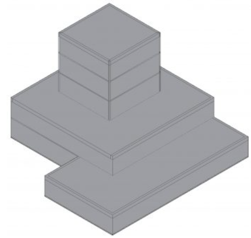
Figure 6.5 Created flat roof shown in the Level 5 view and in 3D view
6.3 CREATE A CONCEPTUAL MASS
- Click the File tab
- Click the New sub-menu arrow and choose the Conceptual Mass option
- Select the Mass.RFT file
- Save the project as Conceptual Mass
- Open the Level 1 view
- Use the Line tool to draw the shape shown in Figure 6.6
- Select the shape
- On the ribbon, click the Create Forms drop-down menu and choose the Solid Form option
- Select the rounded edge along the top face of the mass
- At the center of the Toggle tool
 , click the black circle and drag the edges inward a short distance
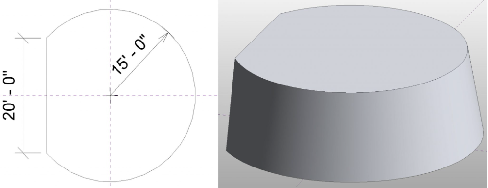
Figure 6.6 Conceptual mass shown with dimensions in plan view and in 3D view - On the ribbon, click the Load in Project and Close
 icon
icon - Make sure the Place on Workplace
 is selected
 - Place the mass by the building
- Use the Move tool
 to connect the Conceptual Mass to the Mass Building as shown in Figure 6.7
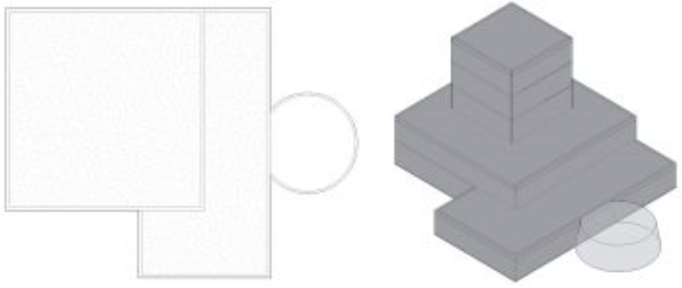
Figure 6.7 Connected masses shown in the Level 1 view and in 3D view
Apply a Curtain wall to a conceptual mass
- Click the Architectural tab
- Click the Curtain System icon

- Select the tilted curved wall
- In the Properties Palette click the Edit Type button
- Click the Duplicate button
- Change the name to 2’ X 5’ and click OK
- Change the following parameters
- Curtain Panel: System Panel: Glazed
- Grid 1:
- Layout: Maximum Spacing
- Spacing: 2’ 0”
- Check the box by Adjust for Mullion Size
- Grid 2:
- Layout: Maximum Spacing
- Spacing: 5’ 0”
- Check the box by Adjust for Mullion Size
- Click OK
- Click the Create System icon

- On the Architecture tab, click the Mullion icon

- Click the All Grid Lines icon

- Use the Type Selector to choose the 1.5” X 2.5” rectangular
- Select the curtain wall
- Add a roof by using the Roof by Face icon
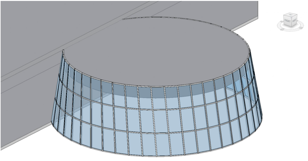
Figure 6.8 Conceptual Mass with applied curtain wall in 3D view