
7: Model In-Place
- Page ID
- 88767

\( \newcommand{\vecs}[1]{\overset { \scriptstyle \rightharpoonup} {\mathbf{#1}} } \) \( \newcommand{\vecd}[1]{\overset{-\!-\!\rightharpoonup}{\vphantom{a}\smash {#1}}} \)\(\newcommand{\id}{\mathrm{id}}\) \( \newcommand{\Span}{\mathrm{span}}\) \( \newcommand{\kernel}{\mathrm{null}\,}\) \( \newcommand{\range}{\mathrm{range}\,}\) \( \newcommand{\RealPart}{\mathrm{Re}}\) \( \newcommand{\ImaginaryPart}{\mathrm{Im}}\) \( \newcommand{\Argument}{\mathrm{Arg}}\) \( \newcommand{\norm}[1]{\| #1 \|}\) \( \newcommand{\inner}[2]{\langle #1, #2 \rangle}\) \( \newcommand{\Span}{\mathrm{span}}\) \(\newcommand{\id}{\mathrm{id}}\) \( \newcommand{\Span}{\mathrm{span}}\) \( \newcommand{\kernel}{\mathrm{null}\,}\) \( \newcommand{\range}{\mathrm{range}\,}\) \( \newcommand{\RealPart}{\mathrm{Re}}\) \( \newcommand{\ImaginaryPart}{\mathrm{Im}}\) \( \newcommand{\Argument}{\mathrm{Arg}}\) \( \newcommand{\norm}[1]{\| #1 \|}\) \( \newcommand{\inner}[2]{\langle #1, #2 \rangle}\) \( \newcommand{\Span}{\mathrm{span}}\)\(\newcommand{\AA}{\unicode[.8,0]{x212B}}\)
Open and work in the same project file from Chapters 1 through 5
7.1 MODEL IN-PLACE
Parametric Bench
- Open the Level 4 view from the Project Browser
- Click on the View tab
- Click on the Section icon

- Click on the West side of the building to start the section cut then drag the cursor over and click to finish the section cut on the East side of the building as shown in Figure 7.1
- Place another section cut from the Northside to the Southside
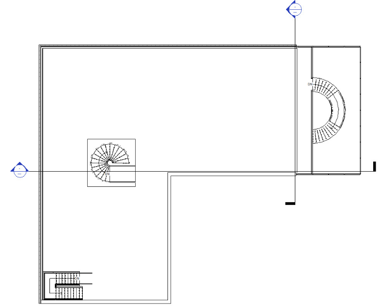
Figure 7.1 Section cuts shown in the Level 4 plan view - Click on the Architecture tab
- Click the Component icon
 drop-down arrow
 - Click the Model In-Place icon

- In the Family Category and Parameter window, select the Furniture option and click OK
- Name the mass “Bench” and click OK
- In the Create tab on the Ribbon, click the Sweep Blend Icon

- Click the Sketch Path icon

- From the Draw panel choose the Center-Ends Arc
 and begin by drawing a 10’ radius then drag the mouse out to draw a 90-degree angle as shown in Figure 7.2
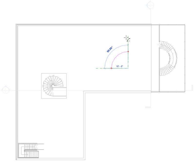
Figure 7.2 Sweep blend path drawn with the Center-Ends Arc tool - Click the green
 checkmark to finish sketching the path
 - Click the Select Profile 1 icon
 on the ribbon
 - Click the Edit Path icon

- In the Go to View window choose the South Elevation and click Open View
- Use the Line tool
 and Spline tool
  T to draw a chair-like outline as shown in Figure 7.3
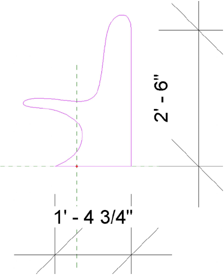
Figure 7.3 Curvilinear chair outline shown in elevation - Click the green checkmark to complete profile 1
- Click the Select Profile 2 icon
 on the ribbon
 - Click the Edit Path icon
- In the Go to View window choose the East Elevation and click Open View
- Use the Line tool and Spline tool to draw a stool-like outline as shown in Figure 7.4
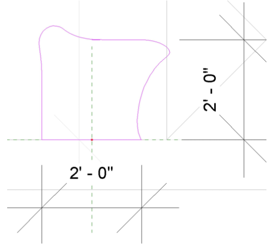
Figure 7.4 Curvilinear stool outline shown in elevation - Click the green checkmark to complete profile 2
- In the 3D view select the bench
- In the Properties Palette next to <By Category> click the 3 dot icon

- Select the default material Wood – Stained and click OK
- In the Level 4 view go to the Create tab and click the Void Form icon
 drop-down menu
 - Click the Void Extrusion option

- Use the Line tool to draw a 1” X 4’0” rectangle that cuts through the bench
- On the Options Bar change the depth to 4’0″
- Click the green checkmark to finish the extrusion
- Under the Create tab, click on the Model Line icon

- Draw two lines from the ends of the bench to the center radius as shown in Figure 7.5
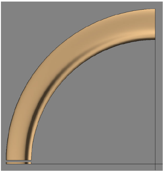
Figure 7.5 Bench shown in plan view with the first extrusion cut and model lines - Check an elevation view that the extrusion cuts through the whole sweep
- In the Level 4 view select the void
- Under the Create tab in the Modify panel, select the Array tool

- Click and drag the blue circle at the center of the void to the intersection of the model lines as shown in Figure 7.6
- On the Options Bar change the following items
- Select the Radial icon
- Change the Number to 30
- Select the option Move to: Last
- Click once on the lower model line and drag up to the second model line which will create a 90-degree array
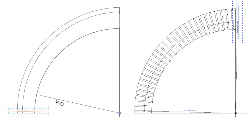
7.6 (left) First void extrusion and (right) void extrusion array - Once all the voids have been placed click the green checkmark to finish the Bench mass
TIP
If the array spreads past 90 degrees click and drag the blue circle at the obtuse end back to 90 degrees
If the voids are orange then they have not cut the form. In the Modify tab, select the Cut icon from the Geometry panel. Click the void first then the bench form
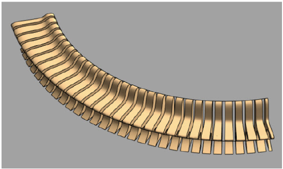
Figure 7.7 Completed Parametric Bench
7.2 In-Place Model
Wall with 3D Geometric Pattern
- Open the 3D view, Level 4 View, and Section 2 view. If any other views are open, close them out.
- Type WT to tile the windows and ZA to zoom all the windows
- Click the Architecture tab
- Click on the Wall icon

- Choose the Type Selector to choose the 4 7/8” Interior Partition Wall
- Change the Top Constraint to Unconnected with a Height of 8’0”
- Draw an 8-ft wall
- In the Section 2 view, click on the Annotate tab
- Click on the Detail Lines icon

- In the East view, draw the pattern as shown in Figure 7.8 with the Line tool
TIP
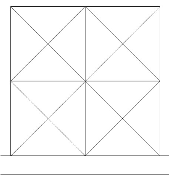
Figure 7.8 Detail line annotation pattern shown in the Section 2 view - In the Level 4 view click on the Massing & Site
- Click the In-Place Mass icon

- Name the mass 3D Pattern Wall and click OK
- In the Level 4 view, click the Plane icon
 on the Ribbon
 - Draw a line across the East facing wall and change the name to Ref 1
- Draw a second line 6” from the first and change the name to Ref 2 (See Figure 7.9)
- In the East view, select the Reference icon

- Select the Point Element tool
 as shown in Figure 7.9
 - Select the Draw on Work Plane icon

- On the Option Bar, change the Placement plane to Reference Plane: Ref 1
- Place an element point at the corners of each square as shown in Figure 7.9
- On the Option Bar, change the Placement plane to Reference Plane: 2
- Place an element point at the center intersection of each square as shown in Figure 7.9
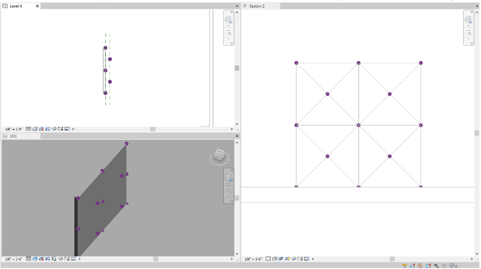
Figure 7.9 (top left) shows point elements on Ref1 and Ref2 and (right) shows points in Section 2 view - In the 3D view, click the create tab
- Click the Reference icon
- Click the Line tool
- On the Option Bar make sure 3D Snapping and Chain are checked
- In the Section 2 view, draw a line from dot to dot. Be sure to watch the 3D view in case the line does not snap to the element points. Once the entire wall is complete as shown in Figure 7.10, proceed to the next step
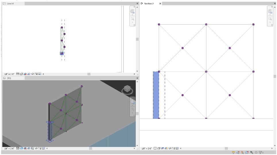
Figure 7.10 Connected reference lines shown in Level 4 view, 3D view and Section 2 viewTIP
- In the 3D view, click the Modify tool
 from the Ribbon
 - While holding down the Control key, select 3 reference lines that create a triangle as shown in Figure 7.11
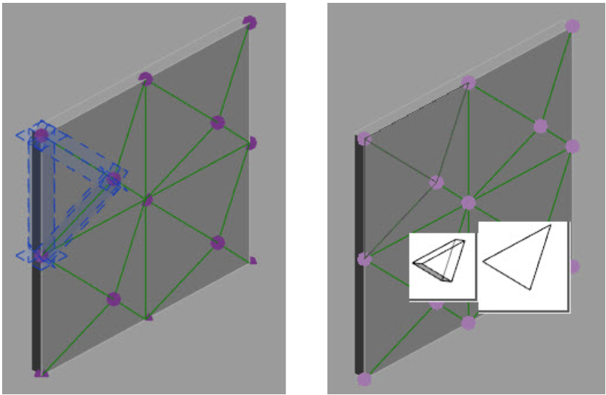
Figure 7.11 (left) Three selected reference planes used to create a solid form and (right) options to create a solid - On the ribbon, click the Create Form
 drop-down arrow and click the Solid Form
- Two images will pop-up, click the 2D (flat) image on the right as shown in Figure 7.11
- Repeat steps 29 through 32 until the entire wall has been created.
TIP
- Once the previous step has been completed for the entire wall, click the green checkmark to finish the mass as shown in Figure 7.12
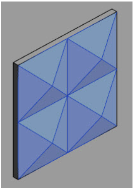
Figure 7.12 Completed creation into solid formsCreating Wall Types for the 3D Pattern Wall
- Click the Architecture tab
- Use the Type Selector to choose the Generic 5”
- Click the Edit Type button
- Duplicate and change the name to Bronze Wall
- Click the Edit button next to Structure
- Change the thickness to 1”
- Click the 3-dot icon next under Material
- Click the Create Material icon

- Click the option to Create a new material
- Rename the material Bronze Wall
- Click the Asset Library icon

- Expand the Appearance Library
- Expand the Metal section
- Click the Bronze option
- Next to the Bronze Polished click the Replace Asset icon

- Click Apply and OK
- Click OK to close the Edit Assembly and the Type Properties
- Create two more wall types with the following parameters
- Wall 2: Grey Wall, 1” thick, Fabric – Fabric (Grey)
- Wall 3: White Wall, 1” thick, Paint – White
- On the Architecture tab, click the Wall icon drop-down arrow and click the Wall By Face icon

- Use the Type Selector to choose the Bronze Wall
- Click 1 triangle from each square at random to apply the Bronze Wall by face
- Change to the Grey Wall and select one triangle at random to add a wall
- Change to the White Wall and do the same for the remaining triangles
- ess ESC twice to exit the command
TIP
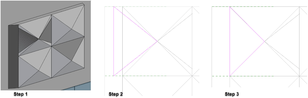
Figure 7.13 Steps 1 through 3 to fix Wall by Face errors
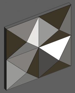
Figure 7.14 Completed 3D Wall
Curvilinear Façade
- Under the Massing & Site tab click the In-Place icon
- Name the mass Curvilinear Façade and click OK
- Open the Level 1 view
- On the ribbon click the Plane icon
- Draw 5 reference planes as shown in Figure 7.15
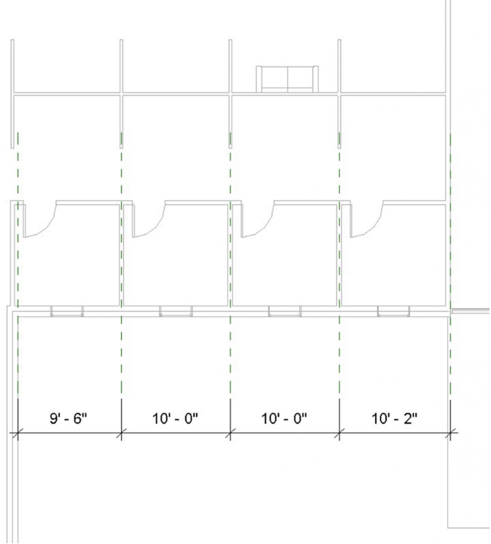
Figure 7.15 Reference planes shown in Level 1 view - Change the reference plane names to 1, 2, 3, 4, and 5 respectively from left to right
- In the East view, select the Model icon
- On the Option Bar change the Placement Plane to Reference Plane: 1
- Use the Line tool and Spline tool to draw the profile shown in Figure 7.16
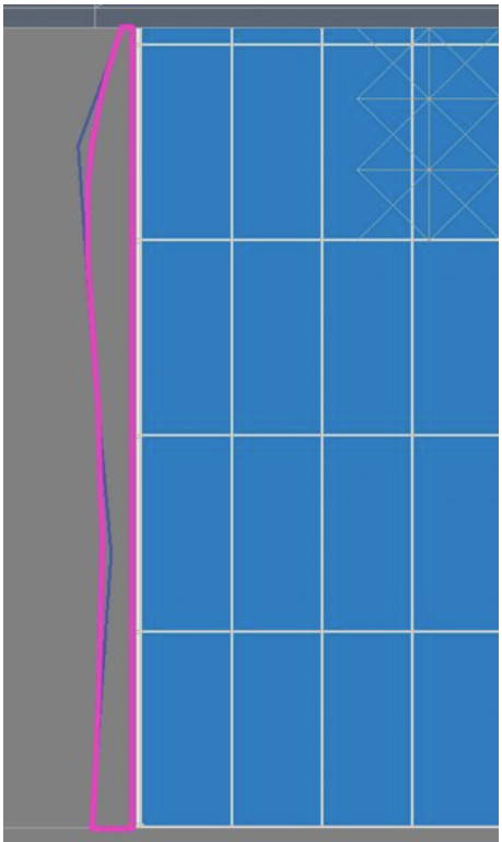
Figure 7.16 Profile drawn on Reference plane: 1 shown in the East view - Continue steps 7 through 10 to draw 4 more profiles on reference planes 2, 3, 4 and 5 as shown in Figure 7.17
TIP
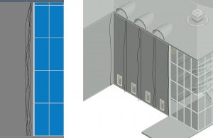
Figure 7.17 All reference planes are shown in the East view and 3D view - In the 3D view select all 5 profiles by holding down the Control key
- On the Ribbon click the Create Form drop-down and choose the Solid Form icon
- Select the exterior face of the wall behind the mass solid
- In the Modify tab select the Set icon

- Select the exterior face of the wall behind the mass solid
- In the Level 1 view, choose the Model icon
- Click the rectangle tool
 and draw a box around each window
 - Select one of the rectangles
- On the ribbon click the Create Form drop-down and choose the Void Form icon
- Use the green gumball arrow and pull it towards the exterior of the building to cut through the façade. See Figure 7.18
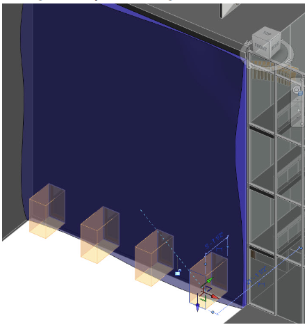
Figure 7.18 Void extrusion shown cutting through the mass solid - Click the green checkmark to finish the mass
- Under the Architecture tab, click on the wall icon drop-down menu and select the Wall By Face icon
- Apply a Generic – 6” Masonry wall to all the sides of the mass.
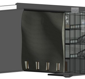
Figure 7.19 Completed Curvilinear façade shown in 3D view