
8: Schematic Design and Room and Color Fill Plans
- Page ID
- 88768

\( \newcommand{\vecs}[1]{\overset { \scriptstyle \rightharpoonup} {\mathbf{#1}} } \)
\( \newcommand{\vecd}[1]{\overset{-\!-\!\rightharpoonup}{\vphantom{a}\smash {#1}}} \)
\( \newcommand{\dsum}{\displaystyle\sum\limits} \)
\( \newcommand{\dint}{\displaystyle\int\limits} \)
\( \newcommand{\dlim}{\displaystyle\lim\limits} \)
\( \newcommand{\id}{\mathrm{id}}\) \( \newcommand{\Span}{\mathrm{span}}\)
( \newcommand{\kernel}{\mathrm{null}\,}\) \( \newcommand{\range}{\mathrm{range}\,}\)
\( \newcommand{\RealPart}{\mathrm{Re}}\) \( \newcommand{\ImaginaryPart}{\mathrm{Im}}\)
\( \newcommand{\Argument}{\mathrm{Arg}}\) \( \newcommand{\norm}[1]{\| #1 \|}\)
\( \newcommand{\inner}[2]{\langle #1, #2 \rangle}\)
\( \newcommand{\Span}{\mathrm{span}}\)
\( \newcommand{\id}{\mathrm{id}}\)
\( \newcommand{\Span}{\mathrm{span}}\)
\( \newcommand{\kernel}{\mathrm{null}\,}\)
\( \newcommand{\range}{\mathrm{range}\,}\)
\( \newcommand{\RealPart}{\mathrm{Re}}\)
\( \newcommand{\ImaginaryPart}{\mathrm{Im}}\)
\( \newcommand{\Argument}{\mathrm{Arg}}\)
\( \newcommand{\norm}[1]{\| #1 \|}\)
\( \newcommand{\inner}[2]{\langle #1, #2 \rangle}\)
\( \newcommand{\Span}{\mathrm{span}}\) \( \newcommand{\AA}{\unicode[.8,0]{x212B}}\)
\( \newcommand{\vectorA}[1]{\vec{#1}} % arrow\)
\( \newcommand{\vectorAt}[1]{\vec{\text{#1}}} % arrow\)
\( \newcommand{\vectorB}[1]{\overset { \scriptstyle \rightharpoonup} {\mathbf{#1}} } \)
\( \newcommand{\vectorC}[1]{\textbf{#1}} \)
\( \newcommand{\vectorD}[1]{\overrightarrow{#1}} \)
\( \newcommand{\vectorDt}[1]{\overrightarrow{\text{#1}}} \)
\( \newcommand{\vectE}[1]{\overset{-\!-\!\rightharpoonup}{\vphantom{a}\smash{\mathbf {#1}}}} \)
\( \newcommand{\vecs}[1]{\overset { \scriptstyle \rightharpoonup} {\mathbf{#1}} } \)
\(\newcommand{\longvect}{\overrightarrow}\)
\( \newcommand{\vecd}[1]{\overset{-\!-\!\rightharpoonup}{\vphantom{a}\smash {#1}}} \)
\(\newcommand{\avec}{\mathbf a}\) \(\newcommand{\bvec}{\mathbf b}\) \(\newcommand{\cvec}{\mathbf c}\) \(\newcommand{\dvec}{\mathbf d}\) \(\newcommand{\dtil}{\widetilde{\mathbf d}}\) \(\newcommand{\evec}{\mathbf e}\) \(\newcommand{\fvec}{\mathbf f}\) \(\newcommand{\nvec}{\mathbf n}\) \(\newcommand{\pvec}{\mathbf p}\) \(\newcommand{\qvec}{\mathbf q}\) \(\newcommand{\svec}{\mathbf s}\) \(\newcommand{\tvec}{\mathbf t}\) \(\newcommand{\uvec}{\mathbf u}\) \(\newcommand{\vvec}{\mathbf v}\) \(\newcommand{\wvec}{\mathbf w}\) \(\newcommand{\xvec}{\mathbf x}\) \(\newcommand{\yvec}{\mathbf y}\) \(\newcommand{\zvec}{\mathbf z}\) \(\newcommand{\rvec}{\mathbf r}\) \(\newcommand{\mvec}{\mathbf m}\) \(\newcommand{\zerovec}{\mathbf 0}\) \(\newcommand{\onevec}{\mathbf 1}\) \(\newcommand{\real}{\mathbb R}\) \(\newcommand{\twovec}[2]{\left[\begin{array}{r}#1 \\ #2 \end{array}\right]}\) \(\newcommand{\ctwovec}[2]{\left[\begin{array}{c}#1 \\ #2 \end{array}\right]}\) \(\newcommand{\threevec}[3]{\left[\begin{array}{r}#1 \\ #2 \\ #3 \end{array}\right]}\) \(\newcommand{\cthreevec}[3]{\left[\begin{array}{c}#1 \\ #2 \\ #3 \end{array}\right]}\) \(\newcommand{\fourvec}[4]{\left[\begin{array}{r}#1 \\ #2 \\ #3 \\ #4 \end{array}\right]}\) \(\newcommand{\cfourvec}[4]{\left[\begin{array}{c}#1 \\ #2 \\ #3 \\ #4 \end{array}\right]}\) \(\newcommand{\fivevec}[5]{\left[\begin{array}{r}#1 \\ #2 \\ #3 \\ #4 \\ #5 \\ \end{array}\right]}\) \(\newcommand{\cfivevec}[5]{\left[\begin{array}{c}#1 \\ #2 \\ #3 \\ #4 \\ #5 \\ \end{array}\right]}\) \(\newcommand{\mattwo}[4]{\left[\begin{array}{rr}#1 \amp #2 \\ #3 \amp #4 \\ \end{array}\right]}\) \(\newcommand{\laspan}[1]{\text{Span}\{#1\}}\) \(\newcommand{\bcal}{\cal B}\) \(\newcommand{\ccal}{\cal C}\) \(\newcommand{\scal}{\cal S}\) \(\newcommand{\wcal}{\cal W}\) \(\newcommand{\ecal}{\cal E}\) \(\newcommand{\coords}[2]{\left\{#1\right\}_{#2}}\) \(\newcommand{\gray}[1]{\color{gray}{#1}}\) \(\newcommand{\lgray}[1]{\color{lightgray}{#1}}\) \(\newcommand{\rank}{\operatorname{rank}}\) \(\newcommand{\row}{\text{Row}}\) \(\newcommand{\col}{\text{Col}}\) \(\renewcommand{\row}{\text{Row}}\) \(\newcommand{\nul}{\text{Nul}}\) \(\newcommand{\var}{\text{Var}}\) \(\newcommand{\corr}{\text{corr}}\) \(\newcommand{\len}[1]{\left|#1\right|}\) \(\newcommand{\bbar}{\overline{\bvec}}\) \(\newcommand{\bhat}{\widehat{\bvec}}\) \(\newcommand{\bperp}{\bvec^\perp}\) \(\newcommand{\xhat}{\widehat{\xvec}}\) \(\newcommand{\vhat}{\widehat{\vvec}}\) \(\newcommand{\uhat}{\widehat{\uvec}}\) \(\newcommand{\what}{\widehat{\wvec}}\) \(\newcommand{\Sighat}{\widehat{\Sigma}}\) \(\newcommand{\lt}{<}\) \(\newcommand{\gt}{>}\) \(\newcommand{\amp}{&}\) \(\definecolor{fillinmathshade}{gray}{0.9}\)8.1 SCHEMATIC DESIGN
Import a CAD file
- In the Level 1 view, click the Insert tab
- Click the Link CAD icon

- Locate the folder and select the file
- At the bottom of the window make sure Current View only is checked
- Use the Positioning drop-down menu to select Manual – Origin
- Click Open
- Use the Measure tool
 and Scale
  if necessary
 - With the drawing selected click the Lock button

TIP
Add the separate plan files to their Revit level respectively
Insert a 2D image
- Under the Insert tab click the Insert Image icon

- Locate the folder, select the file, and click open
- The dashed X represents the image boundary, click anywhere on the canvas to place it
- Use the Measure tool and Scale if necessary
- With the drawing selected click the Lock button
Importing a 3D
3D models can be imported into Revit from Sketch-up and FormIt, but they are imported in as a Family file that acts as guidelines to create a mass as covered in Chapters 6 and 7.
8.2 ROOM AND COLOR FILL
Set room computations
- In the Level 1 view, click the Architecture tab
- Click the Room and Area panels drop-down arrow
- Click the Area and Volume Computation
- In the window, select the Areas Only and At wall finish options
- Click OK
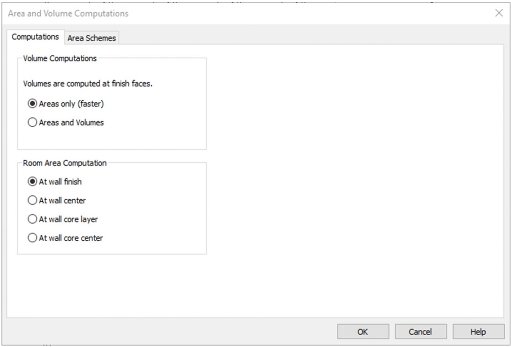
Figure 8.1 Area and Volume Computation window
Place a room individually
- In the Level 1 view, click the Architecture tab
- Under the Rooms & Area panel, click the Room icon

- On the ribbon, make sure that the Tag on Placement icon
 is highlighted in blue. Click to active and un-active the icon. Hover over a room to see the difference.
 - Click to place a room as shown in Figure 8.2
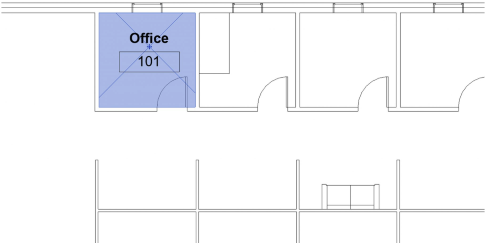
Figure 8.2 Placed room tag shown in the Level 1 view - Hover the cursor over the room tag and select the X
- In the Properties Palette change the Number to 101 and the Name to Office as shown in Figure 8.2
TIP
Add and modify Separation Lines
- Click the architecture tab on the ribbon
- Click the Room Separation icon

- Draw the lines to create separate spaces as shown in Figure 8.3
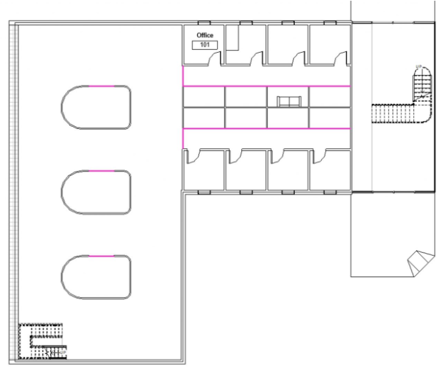
Figure 8.3 Separation Lines indicated by the pink lines - Under the Manage tab, click the Additional settings
 drop-down menu and select the Line Styles option
- Expand the Lines Category by click the + sign
- Next to the <Room Separation>, click the Line Color box
- Change the color to White and click OK
TIP
Create a schedule to place rooms
- Click the View tab
- Click the Schedules icon

- Click the Schedules/Quantities icon

- In the New Schedule window, scroll down the Category list and select the Rooms option
- Click OK
- In the Available fields, separately select Number, Name, and Area and click the Add Parameter button INSERT.
TIP
- Click OK
- On the ribbon, click the Insert Data Row until 23 rows
- For the numbers 101 through 108, select the Room box and use the drop-down to select Office
- For the numbers 109, double-click the Room box and type Cubicle
- For the numbers 110 through 116, use the drop-down to select Cubicle
- Following the steps # through # change the name for the following numbers as shown in Figure 8.4
- 117: Hall
- 118: Hall
- 119: Conference
- 120: Conference
- 121: Conference
- 122: Open Work Space
- 123: Foyer
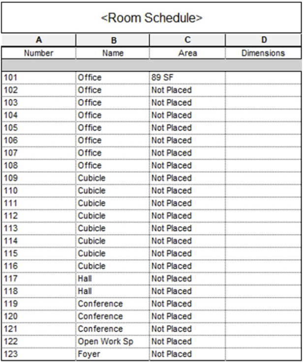
Figure 8.4 Created Room Schedule
- Go back to the Level 1 view
- Click the Architecture tab
- Click the Room icon
- On the Option Bar select the 102 Office from the drop-down menu
- Place it in the office to the right of 101 Office by clicking on the canvas
- Repeat steps 16 and 17 from left to right until all 8 office rooms are placed as shown in Figure 8.5 (Make sure the Tag on Placement is enabled)
- Place the remaining rooms as shown in Figure 8.5
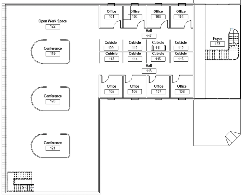
Figure 8.5 Placed rooms
Add and modify a color scheme
- Click the Annotate tab
- Click the Color Fill Legend

- Click on the white space of the canvas to place the Room Legend
- In the Space Type and Color Scheme Change the Space type to Rooms and the Color Scheme to Name the click OK
- Select the Room Legend on the canvas
- Click the Edit Scheme icon

- Change the Room colors to the following RGB values
- Conference: 185 205 182
- Cubicle: 199 233 228
- Foyer: 191 199 175
- Hall: 170 189 198
- Office: 233 226 148
- Open Workspace: 157 206 230
- Click Apply and OK
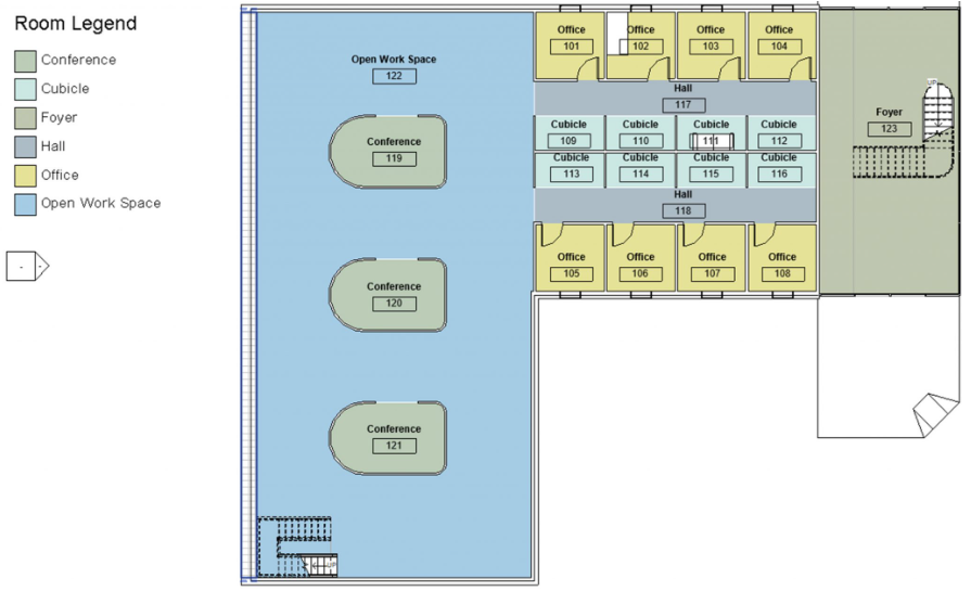
Figure 8.6 Room Legend with modified lighter colors
Add tags and color fill in section
- In the Level 1 view, click the View tab
- Click the Section tag icon

- Draw a section line across the Level 1 view from left to right as shown in Figure 8.7
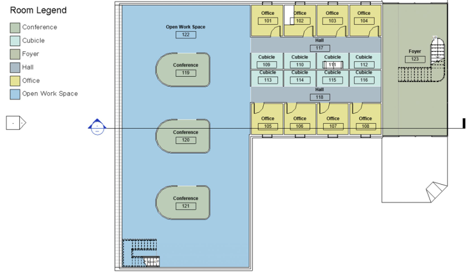
Figure 8.7 Section Line placed on the Level 1 floorplan - In the Project Browser, double-click on Section 1 to open the view
- In the Properties Palette, click the box next to Color Scheme
- In the window, change the Category to Rooms
- Select the Name
- Click Apply and OK
- Click on the Annotation tab
- Click Tag All icon

- In the Tag All Not Tagged window, click the box next to Room Tags
- Click Apply and OK
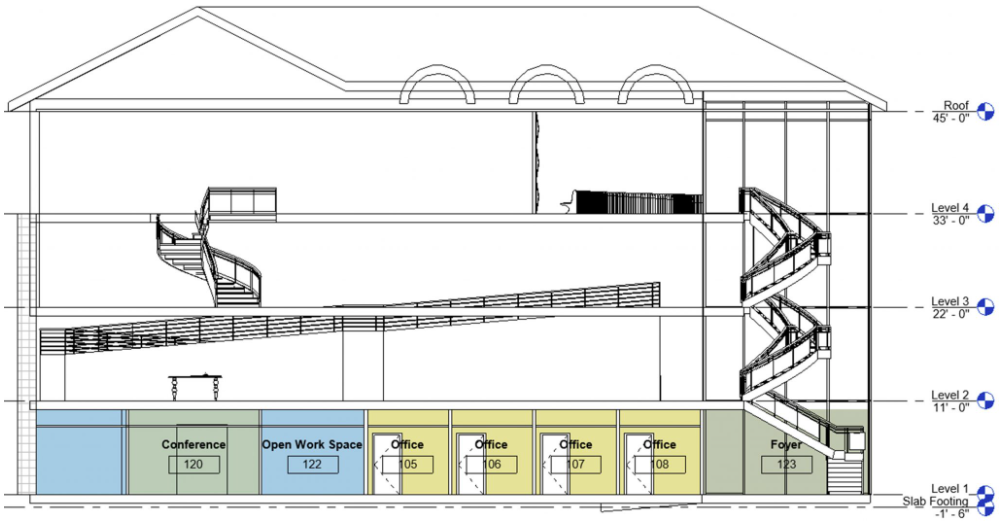
Figure 8.8 Color Scheme and Room tags applied in the Section 1 view.