
9: Materials, Visualization and Rendering
- Page ID
- 88769

\( \newcommand{\vecs}[1]{\overset { \scriptstyle \rightharpoonup} {\mathbf{#1}} } \)
\( \newcommand{\vecd}[1]{\overset{-\!-\!\rightharpoonup}{\vphantom{a}\smash {#1}}} \)
\( \newcommand{\dsum}{\displaystyle\sum\limits} \)
\( \newcommand{\dint}{\displaystyle\int\limits} \)
\( \newcommand{\dlim}{\displaystyle\lim\limits} \)
\( \newcommand{\id}{\mathrm{id}}\) \( \newcommand{\Span}{\mathrm{span}}\)
( \newcommand{\kernel}{\mathrm{null}\,}\) \( \newcommand{\range}{\mathrm{range}\,}\)
\( \newcommand{\RealPart}{\mathrm{Re}}\) \( \newcommand{\ImaginaryPart}{\mathrm{Im}}\)
\( \newcommand{\Argument}{\mathrm{Arg}}\) \( \newcommand{\norm}[1]{\| #1 \|}\)
\( \newcommand{\inner}[2]{\langle #1, #2 \rangle}\)
\( \newcommand{\Span}{\mathrm{span}}\)
\( \newcommand{\id}{\mathrm{id}}\)
\( \newcommand{\Span}{\mathrm{span}}\)
\( \newcommand{\kernel}{\mathrm{null}\,}\)
\( \newcommand{\range}{\mathrm{range}\,}\)
\( \newcommand{\RealPart}{\mathrm{Re}}\)
\( \newcommand{\ImaginaryPart}{\mathrm{Im}}\)
\( \newcommand{\Argument}{\mathrm{Arg}}\)
\( \newcommand{\norm}[1]{\| #1 \|}\)
\( \newcommand{\inner}[2]{\langle #1, #2 \rangle}\)
\( \newcommand{\Span}{\mathrm{span}}\) \( \newcommand{\AA}{\unicode[.8,0]{x212B}}\)
\( \newcommand{\vectorA}[1]{\vec{#1}} % arrow\)
\( \newcommand{\vectorAt}[1]{\vec{\text{#1}}} % arrow\)
\( \newcommand{\vectorB}[1]{\overset { \scriptstyle \rightharpoonup} {\mathbf{#1}} } \)
\( \newcommand{\vectorC}[1]{\textbf{#1}} \)
\( \newcommand{\vectorD}[1]{\overrightarrow{#1}} \)
\( \newcommand{\vectorDt}[1]{\overrightarrow{\text{#1}}} \)
\( \newcommand{\vectE}[1]{\overset{-\!-\!\rightharpoonup}{\vphantom{a}\smash{\mathbf {#1}}}} \)
\( \newcommand{\vecs}[1]{\overset { \scriptstyle \rightharpoonup} {\mathbf{#1}} } \)
\(\newcommand{\longvect}{\overrightarrow}\)
\( \newcommand{\vecd}[1]{\overset{-\!-\!\rightharpoonup}{\vphantom{a}\smash {#1}}} \)
\(\newcommand{\avec}{\mathbf a}\) \(\newcommand{\bvec}{\mathbf b}\) \(\newcommand{\cvec}{\mathbf c}\) \(\newcommand{\dvec}{\mathbf d}\) \(\newcommand{\dtil}{\widetilde{\mathbf d}}\) \(\newcommand{\evec}{\mathbf e}\) \(\newcommand{\fvec}{\mathbf f}\) \(\newcommand{\nvec}{\mathbf n}\) \(\newcommand{\pvec}{\mathbf p}\) \(\newcommand{\qvec}{\mathbf q}\) \(\newcommand{\svec}{\mathbf s}\) \(\newcommand{\tvec}{\mathbf t}\) \(\newcommand{\uvec}{\mathbf u}\) \(\newcommand{\vvec}{\mathbf v}\) \(\newcommand{\wvec}{\mathbf w}\) \(\newcommand{\xvec}{\mathbf x}\) \(\newcommand{\yvec}{\mathbf y}\) \(\newcommand{\zvec}{\mathbf z}\) \(\newcommand{\rvec}{\mathbf r}\) \(\newcommand{\mvec}{\mathbf m}\) \(\newcommand{\zerovec}{\mathbf 0}\) \(\newcommand{\onevec}{\mathbf 1}\) \(\newcommand{\real}{\mathbb R}\) \(\newcommand{\twovec}[2]{\left[\begin{array}{r}#1 \\ #2 \end{array}\right]}\) \(\newcommand{\ctwovec}[2]{\left[\begin{array}{c}#1 \\ #2 \end{array}\right]}\) \(\newcommand{\threevec}[3]{\left[\begin{array}{r}#1 \\ #2 \\ #3 \end{array}\right]}\) \(\newcommand{\cthreevec}[3]{\left[\begin{array}{c}#1 \\ #2 \\ #3 \end{array}\right]}\) \(\newcommand{\fourvec}[4]{\left[\begin{array}{r}#1 \\ #2 \\ #3 \\ #4 \end{array}\right]}\) \(\newcommand{\cfourvec}[4]{\left[\begin{array}{c}#1 \\ #2 \\ #3 \\ #4 \end{array}\right]}\) \(\newcommand{\fivevec}[5]{\left[\begin{array}{r}#1 \\ #2 \\ #3 \\ #4 \\ #5 \\ \end{array}\right]}\) \(\newcommand{\cfivevec}[5]{\left[\begin{array}{c}#1 \\ #2 \\ #3 \\ #4 \\ #5 \\ \end{array}\right]}\) \(\newcommand{\mattwo}[4]{\left[\begin{array}{rr}#1 \amp #2 \\ #3 \amp #4 \\ \end{array}\right]}\) \(\newcommand{\laspan}[1]{\text{Span}\{#1\}}\) \(\newcommand{\bcal}{\cal B}\) \(\newcommand{\ccal}{\cal C}\) \(\newcommand{\scal}{\cal S}\) \(\newcommand{\wcal}{\cal W}\) \(\newcommand{\ecal}{\cal E}\) \(\newcommand{\coords}[2]{\left\{#1\right\}_{#2}}\) \(\newcommand{\gray}[1]{\color{gray}{#1}}\) \(\newcommand{\lgray}[1]{\color{lightgray}{#1}}\) \(\newcommand{\rank}{\operatorname{rank}}\) \(\newcommand{\row}{\text{Row}}\) \(\newcommand{\col}{\text{Col}}\) \(\renewcommand{\row}{\text{Row}}\) \(\newcommand{\nul}{\text{Nul}}\) \(\newcommand{\var}{\text{Var}}\) \(\newcommand{\corr}{\text{corr}}\) \(\newcommand{\len}[1]{\left|#1\right|}\) \(\newcommand{\bbar}{\overline{\bvec}}\) \(\newcommand{\bhat}{\widehat{\bvec}}\) \(\newcommand{\bperp}{\bvec^\perp}\) \(\newcommand{\xhat}{\widehat{\xvec}}\) \(\newcommand{\vhat}{\widehat{\vvec}}\) \(\newcommand{\uhat}{\widehat{\uvec}}\) \(\newcommand{\what}{\widehat{\wvec}}\) \(\newcommand{\Sighat}{\widehat{\Sigma}}\) \(\newcommand{\lt}{<}\) \(\newcommand{\gt}{>}\) \(\newcommand{\amp}{&}\) \(\definecolor{fillinmathshade}{gray}{0.9}\)9.1 MATERIALS
Create a Material
Until this chapter materials were created while an element was modified. A material can be created without having the make or attach it to an element. When a material is created through this process it is available in all material windows for quick access.
- Click on the Manage tab
- Click the Material icon

- In the Search bar type Oak
- Select the Oak Flooring
- At the bottom of the window click the Creates Material icon
 and select the Duplicate option
 - Select the duplicated material and rename the material New Oak Flooring and click the Graphics tab on the right
Graphics tab
- The Surface Pattern is shown in plan and 3D views to depict how the floor planks are laid, click the box next to pattern and change it to the Wood Board Wide
- The Cut Pattern is shown in section, click the box next to Foreground Pattern and change it to Diagonal Up
- Click the Appearance tab
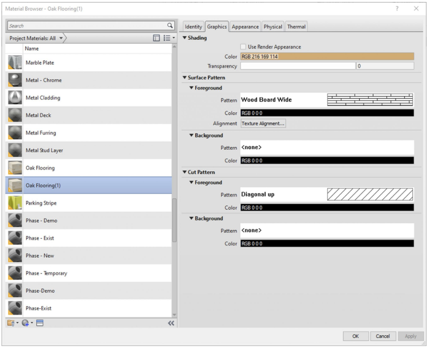
Figure 9.1 Graphics tab options
Appearance tab
- Select the box next to Image. This window is used to change the Image, Brightness, Position, Rotation, Scale and how the image repeats once applied to an element
- Change the image to Wild_Cherry_natural1 and the Scale to 10’ x 10’
- Click Done
TIP
- The Relief Pattern is used to show if a pattern is rough or smooth. Toggle the amount or use the text bar to adjust the relief pattern to 1.25
- Once done click Apply then OK. This material will be available throughout the project
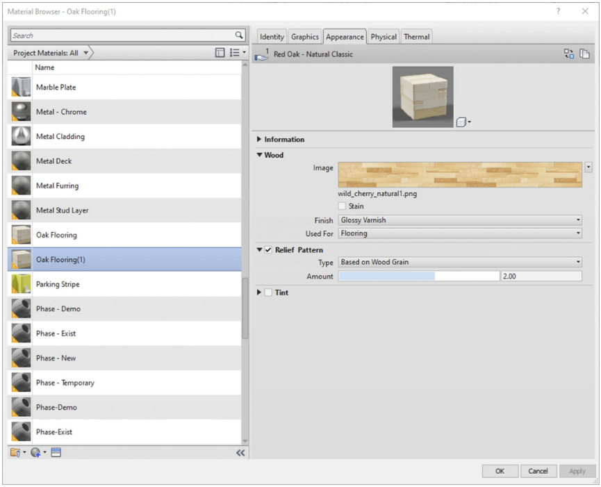
Figure 9.2 Appearance tab options
Asset Library
- Click on the Manage tab
- Click the Material icon
- At the bottom click the Creates Material icon and select the Create New Material option
- Name it Metal Panel
- Click the Asset Library icon

- In the Search bar type Metal Panels – Blue and press the Enter key
- Select the Replace Asset
 on the right side of the options bar
 - Click the X to close the Asset Library
- Under Appearance click the Relief Pattern Image Box
- Click the source and change it to TileRectBump and click OK
- Click Apply and OK
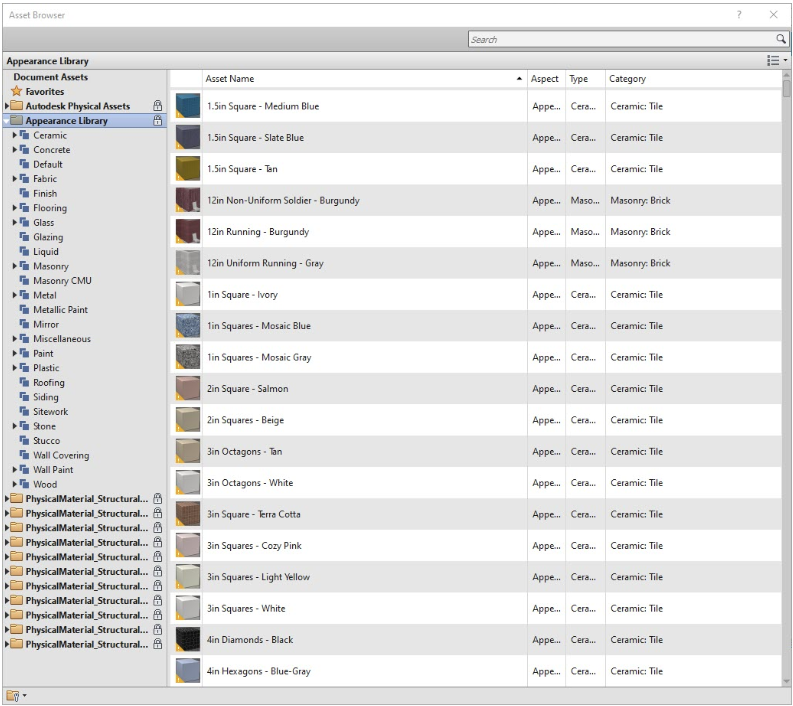
Figure 9.3 Asset Library window
Assign a Material by Element
- Open the 3D view, select the wall on the first floor that separates the foyer from the offices as shown in Figure 9.4
- In the Properties Palette, click the Edit Type button
- Click the Duplicate button and name the wall Metal Panel
- Next to Structure click the Edit button
- Change both Finish 2 [5] to the Metal Panel material by clicking the 3 dots button

- Click OK to close the windows
- To view the result, make sure the Visual Style is set to Realistic
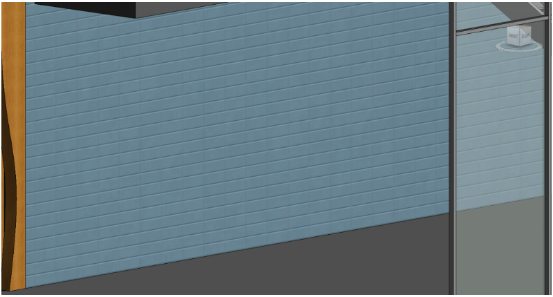
Figure 9.4 Metal Panel material applied to an existing wall
Assign a material using the Paint tool
- In the 3D view, adjust the view to see the mezzanines as shown in Figure 9.5
- Click the Modify tab
- Click the Paint tool

- Select the New Oak Flooring
- Hover over the Level 2 and when the top face is highlighted, click to place the material
- Do the same for Level 3 and 4 as shown in Figure 9.5
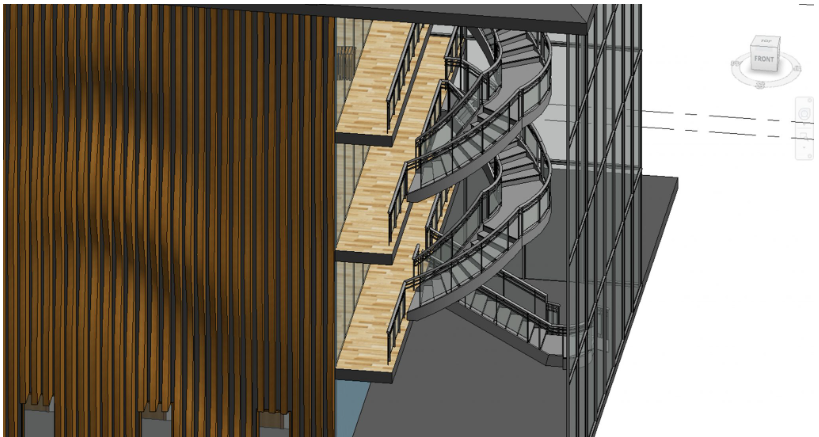
Figure 9.5 Applied New Oak Floor material
9.2 VISUALIZATION
Create a presentation elevation view
- In the Project Browser, locate the Elevations
- Right-click the South elevation and click Duplicate View then Duplicate
- Rename the copy South Presentation
- On the View Control Bar, change the Visual Style to Shaded
 and Detail Level to Fine
- Hide the reference levels and any other visible markers
- In the Properties Palette, click the Edit button next to Graphic Display Options
- Change the following properties
- Model Display: check the Smooth Lines with Anti-Aliasing
- Shadows: check both Cast Shadows and Show Ambient Shadows
- Depth Cueing: Check Show Depth, Fade start to 25, Fade Limit to 25
- Lighting: Sun to 80, Ambient Light to 10, Shadows to 60
- Click OK to accept these changes
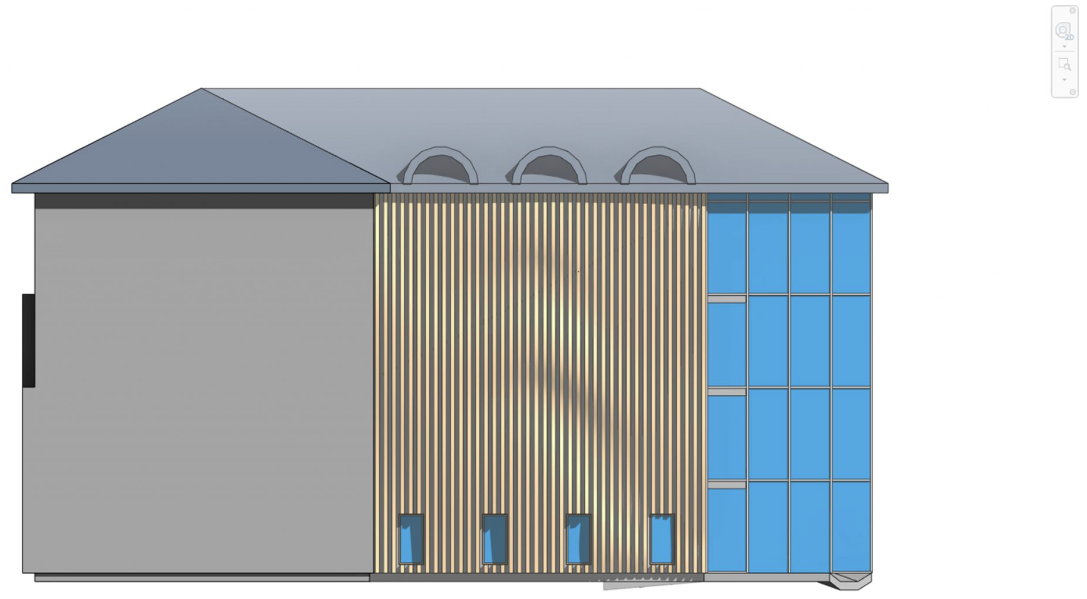
Figure 9.6 South Presentation view
Create a presentation 3D view
- In the project browser, create a duplicate 3D view and name it 3D Presentation
- Change the Visual Style to Shaded and the Detail Level to Fine
- On the View Control Bar, click the Visual Style icon and click Graphic Display Option
- Change the following parameters
- Model Display: check the Smooth Lines with Anti-Aliasing
- Shadows: check both Cast Shadows and Show Ambient Shadows
- Lighting: Sun to 30, Ambient Light to 20, Shadows to 30
- Background: Gradient
- Click OK to accept these changes
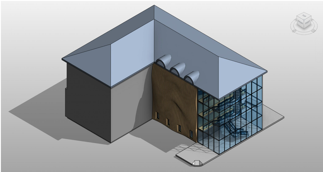
Figure 9.7 3D Presentation
Exploded 3D Model
- Duplicate the 3D view again and name it 3D Exploded Axon
- Click the Modify icon

- Select the roof
- Click the Displace Element icon

- Use the blue toggle arrow and pull the roof up
- Do the same for the Ceiling and the three roof extrusions as shown in Figure 9.8
- Select the roof and click the Path icon
 on the ribbon
 - Hover the cursor over the corners of the roof and click to place a dashed line at each corner. These should automatically snap to the corners of the selected element
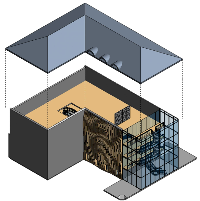
Figure 9.8 Exploded roof with path lines
- Zoom into the punched opening windows along the first floor
- Select the first window, Click the Displace Element icon and drag it from the wall using the green toggle arrow
- Select one of the southern walls and click the Displace Element icon
- Select the wall again and click the Edit icon

- With the Add option enabled, select the other two walls
- Click the green
 checkmark to finish editing
 - Use the green toggle arrow to pull the elements away from the building
- Add path lines as shown in Figure 9.9
- Pull the windows out from the wall and add path lines
TIP
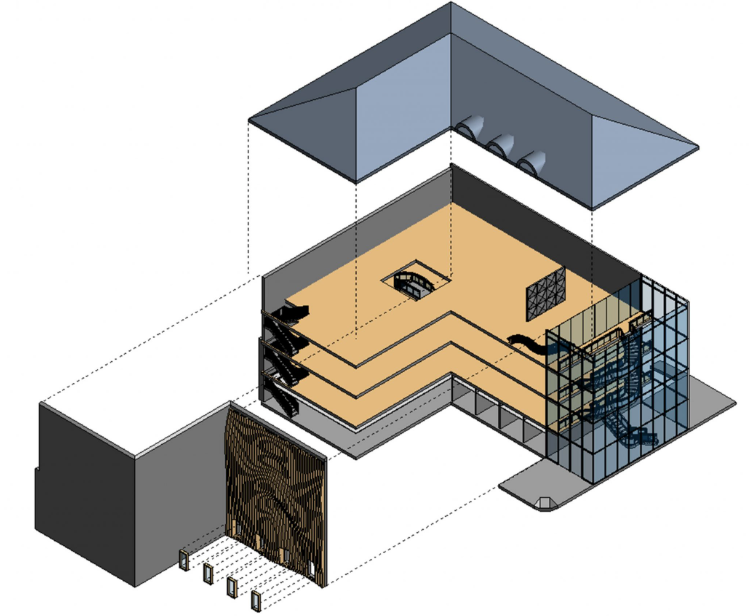
Figure 9.9 Exploded Isometric
9.3 RENDERING
Render a view
- Open the Level 4 floor plan
- Go to the View tab and click the 3D view
 icon drop-down menu
 - Click the Camera icon

- Click and hold the cursor down in the up-right corner of the 4th floor
- Drag the cursor down and slightly to the left to view the curtain wall, parametric bench and 3D wall.
- When the view opens, use the crop region lines to adjust the view
TIP
-Use the Full Navigation Wheel to adjust the view - Click the Render icon

- In the Render window change the following settings
- Setting to Medium
- The Lighting scheme to Exterior: Sun and Artificial
- Style: Sky Cloudy
- Click Render
- Once the process is complete, use the Adjust Exposure levels until the desired effect is reached.
- Export as a jpeg (or another file type that is most appropriate)
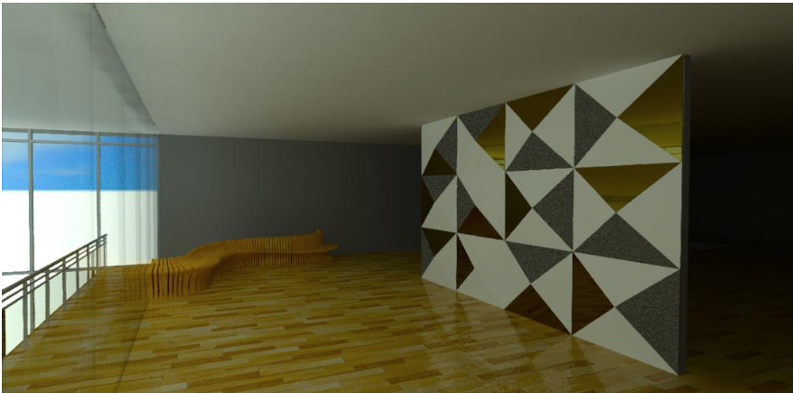
Figure 9.10 Render of Parametric bench and 3D wall
Interactive (Ray Trace) rendering
Ray Trace allows the user to view, set, adjust, and save render views before the final rendering takes place.
- Open the Level 4 floor plan
- Go to the View tab and click the 3D view icon drop-down menu
- Click the Camera icon
- Click and hold the cursor down in the up-right corner of the 4th floor
- Drag the cursor down and slightly to the left to view the curtain wall, parametric bench, and 3D wall.
- When the view opens, use the crop region lines to adjust the view
- Go to the View Control Bar and change the Visual Style to Ray Trace
 . Be patient because the image will take a moment to become clear.
 - Click on the Visual Style icon again
- Click the Graphic Display Option
- Adjust the settings until the desired render is reached
- On the ribbon in the top right corner, click the Save icon

- Name the view
- Click the Close button

- Render the image
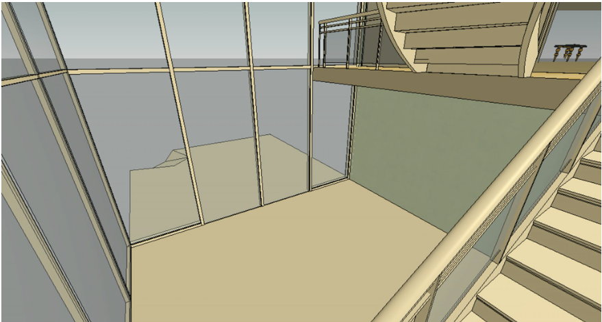
Figure 9.11 Saved render settings before final render takes place
Cloud rendering
Cloud render allows a user to send renderings through the cloud using their AutoDesk account where the final images are processed and received through email. This allows the user to continue working while the image is rendering.
- Click on the View tab
- Click the Render in Cloud icon

- An instruction window will open describing what the process is, click OK to progress forward
- Select the 3D View, Still Image, and Standard quality. Note that some options require credits to be used to purchase higher-quality renders through this option.
- In the Next window, click Render in Background
- After a short period, open your email and retrieve the image
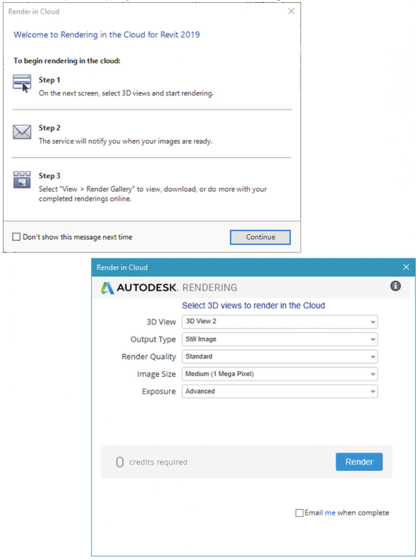
Figure 9.12 Render in Cloud windows