
4: Stairs, Railings and Ramps
- Page ID
- 88764

\( \newcommand{\vecs}[1]{\overset { \scriptstyle \rightharpoonup} {\mathbf{#1}} } \)
\( \newcommand{\vecd}[1]{\overset{-\!-\!\rightharpoonup}{\vphantom{a}\smash {#1}}} \)
\( \newcommand{\dsum}{\displaystyle\sum\limits} \)
\( \newcommand{\dint}{\displaystyle\int\limits} \)
\( \newcommand{\dlim}{\displaystyle\lim\limits} \)
\( \newcommand{\id}{\mathrm{id}}\) \( \newcommand{\Span}{\mathrm{span}}\)
( \newcommand{\kernel}{\mathrm{null}\,}\) \( \newcommand{\range}{\mathrm{range}\,}\)
\( \newcommand{\RealPart}{\mathrm{Re}}\) \( \newcommand{\ImaginaryPart}{\mathrm{Im}}\)
\( \newcommand{\Argument}{\mathrm{Arg}}\) \( \newcommand{\norm}[1]{\| #1 \|}\)
\( \newcommand{\inner}[2]{\langle #1, #2 \rangle}\)
\( \newcommand{\Span}{\mathrm{span}}\)
\( \newcommand{\id}{\mathrm{id}}\)
\( \newcommand{\Span}{\mathrm{span}}\)
\( \newcommand{\kernel}{\mathrm{null}\,}\)
\( \newcommand{\range}{\mathrm{range}\,}\)
\( \newcommand{\RealPart}{\mathrm{Re}}\)
\( \newcommand{\ImaginaryPart}{\mathrm{Im}}\)
\( \newcommand{\Argument}{\mathrm{Arg}}\)
\( \newcommand{\norm}[1]{\| #1 \|}\)
\( \newcommand{\inner}[2]{\langle #1, #2 \rangle}\)
\( \newcommand{\Span}{\mathrm{span}}\) \( \newcommand{\AA}{\unicode[.8,0]{x212B}}\)
\( \newcommand{\vectorA}[1]{\vec{#1}} % arrow\)
\( \newcommand{\vectorAt}[1]{\vec{\text{#1}}} % arrow\)
\( \newcommand{\vectorB}[1]{\overset { \scriptstyle \rightharpoonup} {\mathbf{#1}} } \)
\( \newcommand{\vectorC}[1]{\textbf{#1}} \)
\( \newcommand{\vectorD}[1]{\overrightarrow{#1}} \)
\( \newcommand{\vectorDt}[1]{\overrightarrow{\text{#1}}} \)
\( \newcommand{\vectE}[1]{\overset{-\!-\!\rightharpoonup}{\vphantom{a}\smash{\mathbf {#1}}}} \)
\( \newcommand{\vecs}[1]{\overset { \scriptstyle \rightharpoonup} {\mathbf{#1}} } \)
\( \newcommand{\vecd}[1]{\overset{-\!-\!\rightharpoonup}{\vphantom{a}\smash {#1}}} \)
\(\newcommand{\avec}{\mathbf a}\) \(\newcommand{\bvec}{\mathbf b}\) \(\newcommand{\cvec}{\mathbf c}\) \(\newcommand{\dvec}{\mathbf d}\) \(\newcommand{\dtil}{\widetilde{\mathbf d}}\) \(\newcommand{\evec}{\mathbf e}\) \(\newcommand{\fvec}{\mathbf f}\) \(\newcommand{\nvec}{\mathbf n}\) \(\newcommand{\pvec}{\mathbf p}\) \(\newcommand{\qvec}{\mathbf q}\) \(\newcommand{\svec}{\mathbf s}\) \(\newcommand{\tvec}{\mathbf t}\) \(\newcommand{\uvec}{\mathbf u}\) \(\newcommand{\vvec}{\mathbf v}\) \(\newcommand{\wvec}{\mathbf w}\) \(\newcommand{\xvec}{\mathbf x}\) \(\newcommand{\yvec}{\mathbf y}\) \(\newcommand{\zvec}{\mathbf z}\) \(\newcommand{\rvec}{\mathbf r}\) \(\newcommand{\mvec}{\mathbf m}\) \(\newcommand{\zerovec}{\mathbf 0}\) \(\newcommand{\onevec}{\mathbf 1}\) \(\newcommand{\real}{\mathbb R}\) \(\newcommand{\twovec}[2]{\left[\begin{array}{r}#1 \\ #2 \end{array}\right]}\) \(\newcommand{\ctwovec}[2]{\left[\begin{array}{c}#1 \\ #2 \end{array}\right]}\) \(\newcommand{\threevec}[3]{\left[\begin{array}{r}#1 \\ #2 \\ #3 \end{array}\right]}\) \(\newcommand{\cthreevec}[3]{\left[\begin{array}{c}#1 \\ #2 \\ #3 \end{array}\right]}\) \(\newcommand{\fourvec}[4]{\left[\begin{array}{r}#1 \\ #2 \\ #3 \\ #4 \end{array}\right]}\) \(\newcommand{\cfourvec}[4]{\left[\begin{array}{c}#1 \\ #2 \\ #3 \\ #4 \end{array}\right]}\) \(\newcommand{\fivevec}[5]{\left[\begin{array}{r}#1 \\ #2 \\ #3 \\ #4 \\ #5 \\ \end{array}\right]}\) \(\newcommand{\cfivevec}[5]{\left[\begin{array}{c}#1 \\ #2 \\ #3 \\ #4 \\ #5 \\ \end{array}\right]}\) \(\newcommand{\mattwo}[4]{\left[\begin{array}{rr}#1 \amp #2 \\ #3 \amp #4 \\ \end{array}\right]}\) \(\newcommand{\laspan}[1]{\text{Span}\{#1\}}\) \(\newcommand{\bcal}{\cal B}\) \(\newcommand{\ccal}{\cal C}\) \(\newcommand{\scal}{\cal S}\) \(\newcommand{\wcal}{\cal W}\) \(\newcommand{\ecal}{\cal E}\) \(\newcommand{\coords}[2]{\left\{#1\right\}_{#2}}\) \(\newcommand{\gray}[1]{\color{gray}{#1}}\) \(\newcommand{\lgray}[1]{\color{lightgray}{#1}}\) \(\newcommand{\rank}{\operatorname{rank}}\) \(\newcommand{\row}{\text{Row}}\) \(\newcommand{\col}{\text{Col}}\) \(\renewcommand{\row}{\text{Row}}\) \(\newcommand{\nul}{\text{Nul}}\) \(\newcommand{\var}{\text{Var}}\) \(\newcommand{\corr}{\text{corr}}\) \(\newcommand{\len}[1]{\left|#1\right|}\) \(\newcommand{\bbar}{\overline{\bvec}}\) \(\newcommand{\bhat}{\widehat{\bvec}}\) \(\newcommand{\bperp}{\bvec^\perp}\) \(\newcommand{\xhat}{\widehat{\xvec}}\) \(\newcommand{\vhat}{\widehat{\vvec}}\) \(\newcommand{\uhat}{\widehat{\uvec}}\) \(\newcommand{\what}{\widehat{\wvec}}\) \(\newcommand{\Sighat}{\widehat{\Sigma}}\) \(\newcommand{\lt}{<}\) \(\newcommand{\gt}{>}\) \(\newcommand{\amp}{&}\) \(\definecolor{fillinmathshade}{gray}{0.9}\)Continue working on the same project file from the previous chapters.
4.1 TYPES OF STAIRS
Assembled
Assembled stairs show each riser, tread, and stringer as separate elements like assembled wooden stairs.
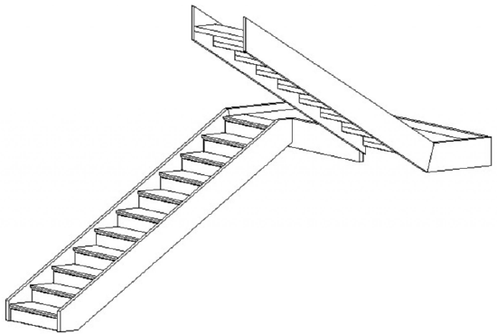
Figure 4.1 Assembled Stair
Monolithic
Monolithic stairs use the same material for treads, risers, and stringers.
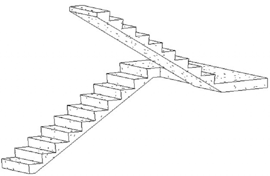
Figure 4.2 Monolithic Stair
Precast
Precast stairs use structural rebar in concrete like a cast-in-place stair would be built on-site.
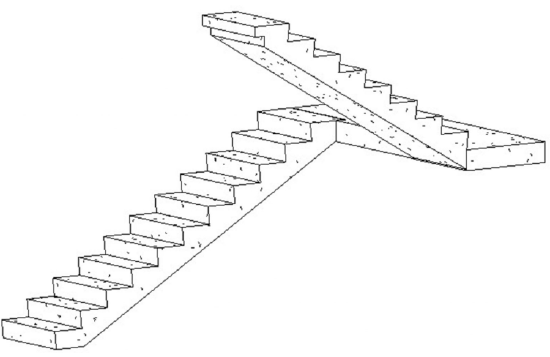
Figure 4.3 Precast Stair
4.2 CREATE STAIRS
Create a straight run stair by component
- Click the Architecture tab
- In the Level 1 view, click the Stair icon

- Use the Type Selector to choose the Assembled Stair
- On the Options Bar, change the Location Line to Exterior Support: Left
- Click to begin the stair as shown in Figure 4.4
- Drag the cursor till it shows 10 risers will be created and 9 risers are remaining
- Click to place the first 10 risers
- Drag the cursor up and place the remaining stairs 9-foot away
- Select the Railing icon
 on the Ribbon
 - Choose the Handrail – Rectangular option and click OK
- Use the Move tool
 if needed to place the stairs in the bottom left corner of the shaft opening
 - In Elevation or 3D view, select the stair and choose the Connect Levels icon
 from the Modify tab
 - Select the level lines 3 and 4 to connect to each other
- Click the green checkmark
 to complete the stair
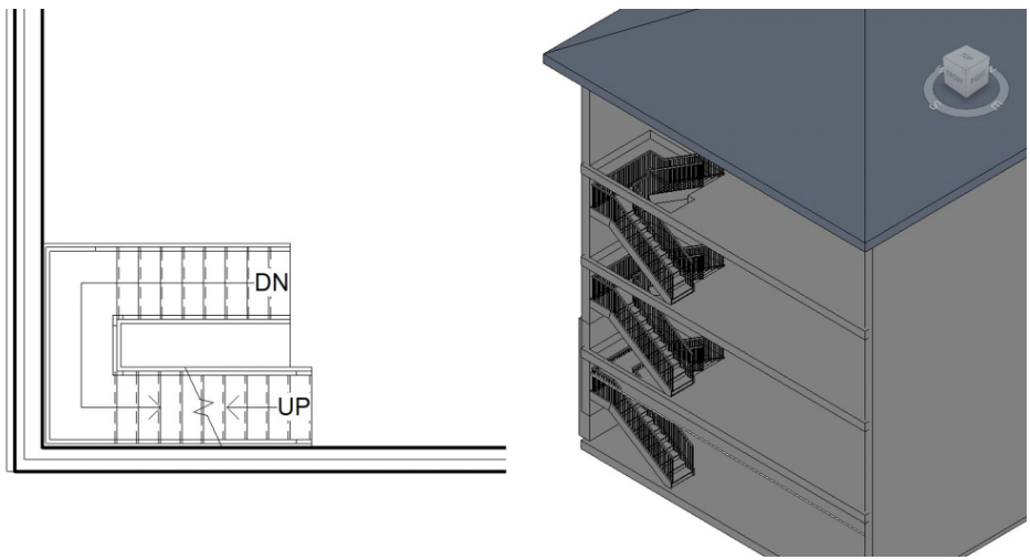
Figure 4.4 Assembly stair in plan view and in 3D view
(One wall in the 3D view is hidden to show the stairs connecting to multiple levels)
Create a custom stair by sketching
- Open the Level 1 view from the Project Browser
- In the Properties Palette, in the Underlay section, change the Range: Base Level to Level 2
- Click the Architecture tab
- Click the Stair icon on the ribbon, under the Circulation panel
- In the Properties Palette, select the Edit Type icon

- In the Type Properties window click the Duplicate button
- Change the name to “7in max riser 1ft tread”
- Change the following parameters
- Maximum Riser Height: 0’ 6.9”
- Minimum Tread Depth: 1’ 0”
- In the Components panel, click the Sketch tool

- Click the Boundary icon

- Following Figure 4.5, use the Line tool
 to draw green boundary lines in the Level 1 floorplan
 - Click the Riser icon

- Following Figure 4.5, use the Line tool and the Start-End-Radius tool
 to draw risers 1 foot apart.
 - Click the Stair Path

- Click to place a connected line from the top riser to the bottom riser
- Click the green checkmark to complete the stair
- Look at the 3D view, if the stair direction is wrong, on the ribbon click the Flip icon

- On the ribbon, select the Railing icon
- The Railing window will open. Change the following parameters
- Choose the Glass Panel – Bottom Fill
- Choose the Stringer option
- Click OK
- Click the green checkmark to complete the stair
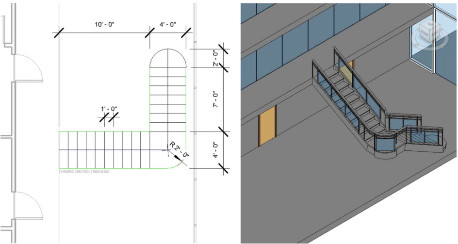
Figure 4.5 Stair sketch in plan view and finished stair in 3D view
(Two walls in the 3D view are hidden to show the custom stair)
TIP
Create a Full-Step spiral stair
- Open the Level 3 floor plan view
- Click the Architecture tab
- Click the Stair icon on the Ribbon, under the Circulation panel
- On the Options Bar change the Actual Run Width to 5’ 0”
- Use the Type Selector to choose the Assembled Stair 7” max riser 11” tread
- In the Properties Palette change the following parameters
- Base Level: Level 3
- Top Level: Level 4
- In the Components panel, click the spiral tool

- In the Level 3 view, click once on the canvas at the center of the 15-foot square opening and drag the cursor out as shown in Figure 4.6 to create a radius of 6’0″
- Type 10” and press the Enter key
- Click the Landing icon

- Use the Line tool to draw a landing to connect the stair to the floor plate as shown in Figure 4.6
- Click the green checkmark to complete the Landing
- On the ribbon, select the Railing icon
- The Railing window will open, change the following parameters
- Click the Glass Panel – Bottom Fill
- Click the Stringer option
- Click the green checkmark to complete the Stair
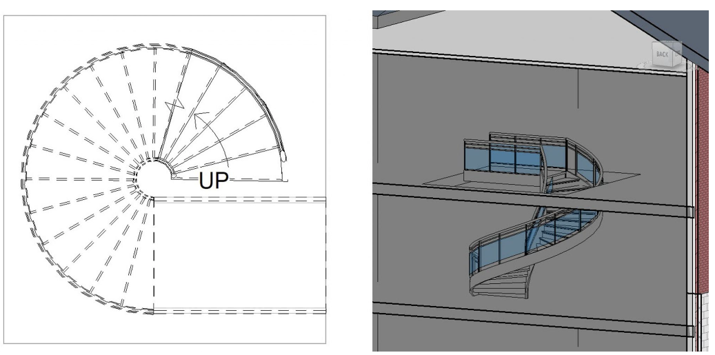
Figure 4.6 Spiral stair in plan view and in 3D view
(The 3D view shown uses a section box to better view the added element. A section box can be added through the Properties Palette)
Create a Center-Ends spiral stair
- In the Level 2 view, click the Architecture tab
- Select the Stair icon from the ribbon, under the Circulation panel
- On the Option Bar change the Actual Run Width to 4’ 0”
- In the Components panel, click the Center-Ends Spiral tool

- Hover the cursor over the center edge of the mezzanine. When the midpoint snap appears (magenta triangle), click to start placing the stair
- Drag the cursor down the mezzanine edge to create a 6-foot radius. Click to begin placing the stair treads
- Drag the cursor up and around until 10 risers are created and 11 risers remain
- Click to finish placing the stairs
- Select the Center-Ends Spiral Tool again
- Select the center radius
- Drag the cursor out from the first 10 steps to create a 6-foot radius and an automatic curved landing is created
- In Elevation or 3D view, select the stair and choose the Connect Levels icon from the Modify tab
- Select the level line 3
- Click the Railing icon
- Select Glass Panel – Bottom Fill
- Click OK
- Click the green checkmark to complete this step
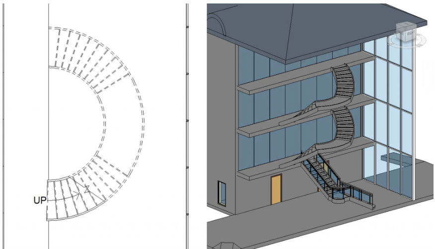
Figure 4.7 Spiral stair in plan view and in 3D view
(Two walls in the 3D view are hidden to better show the custom spiral stair)
4.3 TYPES OF RAILINGS
Glass Panel
Metal Railing with glass panels filling in the bottom area
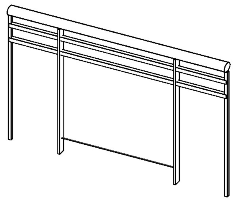
Figure 4.8 Railing Glass Panel in 3D view
Guardrail – Pipe
The typical railing of several horizontal members that have no applied materials.
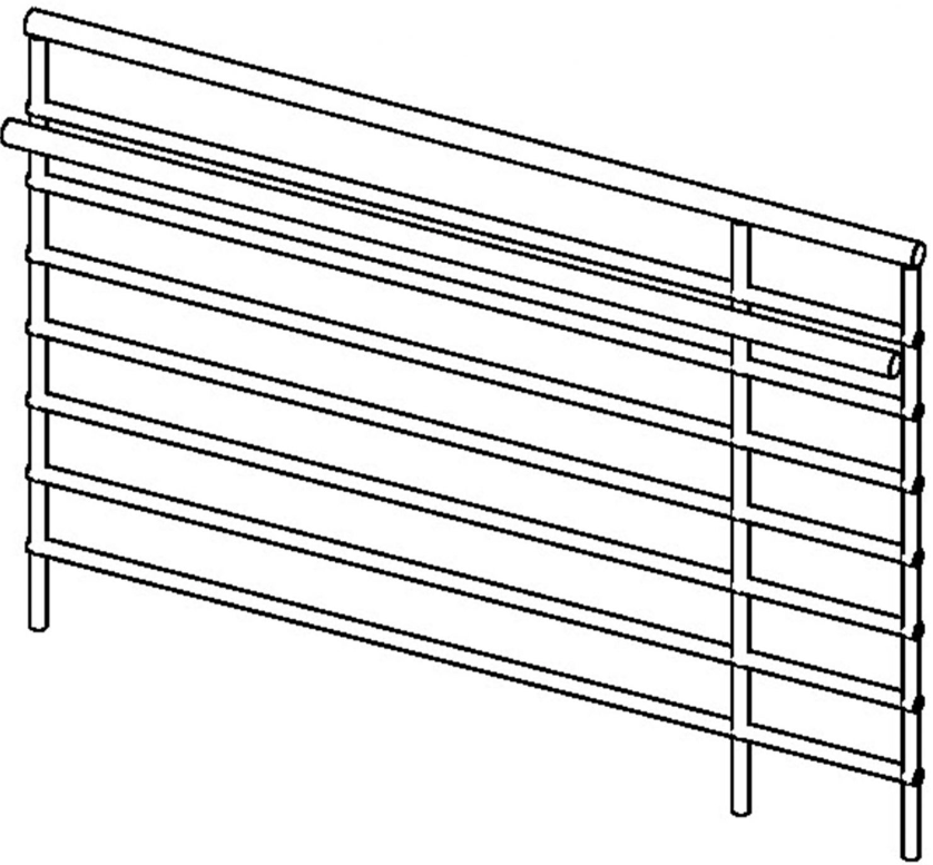
Figure 4.9 Railing Guardrail – Pipe in 3D view
Guardrail – Rectangular
The typical railing of several vertical members that have no applied materials.
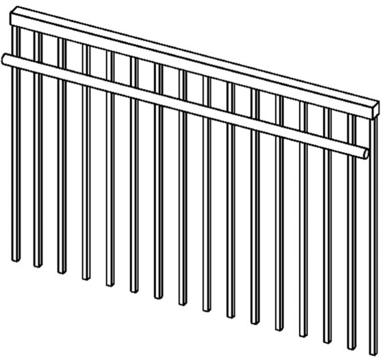
Figure 4.10 Railing Guardrail – Rectangular
Handrail – Pipe
The typical railing of several horizontal members that have no applied materials.
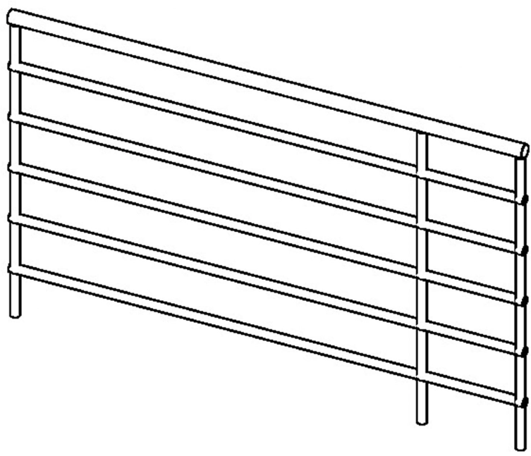
Figure 4.11 Railing Handrail – Pipe
Handrail – Rectangular
The typical railing of several vertical members that have no applied materials.
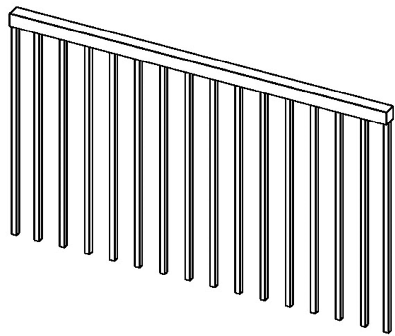
Figure 4.12 Railing Handrail – Rectangular
4.4 CREATE RAILINGS
Create railings using the Line Tool
- In the Level 2 view, click the Architecture tab
- Click the Railing icon drop-down menu from the Circulation Panel
- Use the Type Selector to choose the Glass Panel – Bottom Fill
- Select the Line tool
- Follow Figure 4.13 to draw the first railing in magenta 0’4″ from the edge of the mezzanine
- Click the green checkmark to complete the railing
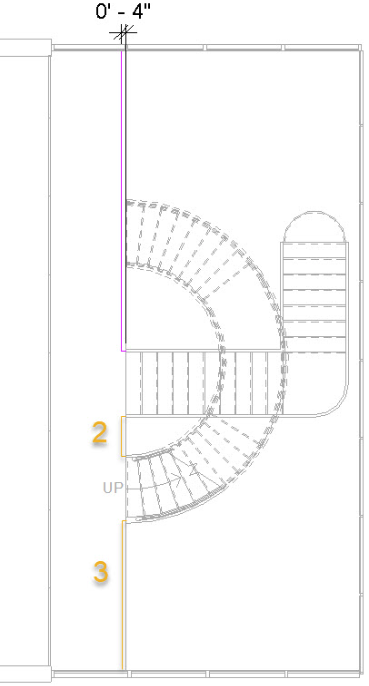
Figure 4.13 Level 2 sketched railings shown in plan view - Each railing must be continuous therefore follow the same steps to complete rails 2 and 3 highlighted in yellow in Figure 4.13
- Click the green checkmark to complete the railing
- Continue to draw the railings for Levels 3 and 4 shown in Figure 4.14
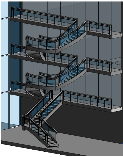
Figure 4.14 Mezzanine railing completed for Levels 2, 3, and 4
(Two walls in the 3D view are hidden to show the railings)
Modify a railing
- In the 3D view, click the View Cube on the top corner between the Left and Front face
- Select the two connecting walls in this view
- Right-click and click Hide in View
- In the sub-menu click Element
- Hold down the Control key and select all of the railings in the Shaft Opening
- Use the Type Selector to choose Handrail – Rectangular
- Click the Edit Type button
- Click the Duplicate button
- Accept the default name change
- Under the Top Rail section, by Type, select the words “Rectangular 2X2” then click the 3 dots button

- Under the Extension Beginning/Bottom set the following parameters
- Extension Style: Wall
- Length: 1’ 0”
- Click OK
- Under the Handrail 1 section, by Type, select the word “<none>” then click the 3 dots button that appears
- Under the Extension Beginning/Bottom change the following parameters
- Extension Style: Post
- Length: 1’ 0”
- Check the box next to Plus Tread Depth
- Click OK
- Under Handrail 1, change the position to Left
- Click OK
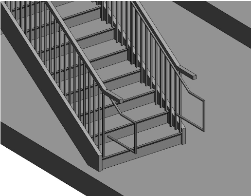
Figure 4.15 Handrail added to the inside of the existing railing
(One wall in the 3D view is hidden to show the stairs and handrailing)
4.5 RAMPS
Create a ramp using the Line Tool
- In the Level 2 view, click the Architecture tab
- Click the Ramp icon
 on the ribbon
 - In the Properties palette, click the Edit Type button
- Duplicate the type and change the name to “My Ramp”
- Change the Maximum Incline Length to 33’ ¼”
- Click OK to accept the changes
- Use the Line tool to begin drawing the first incline of the ramp as shown in Figure 4.16
- Pull the cursor away from the first incline to provide a landing as shown in Figure 4.16
- Complete until there is 0” remaining of the ramp to place
- Click the green checkmark to complete the ramp
- After the ramp is created select the Level 2 floor plate and edit the boundary to include an opening for the ramp to reach level 3
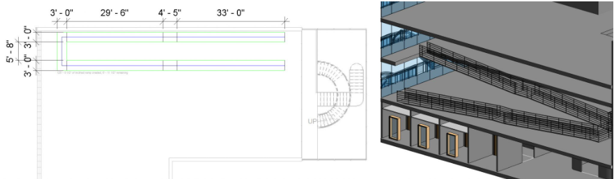
Figure 4.16 Ramp shown in plan view and in 3D view
(One wall in the 3D view is hidden to show the inner railing)
Modify a ramp
- In the Level 2 view, select the ramp
- Click the Edit profile icon

- Working from right to left, select a line
- Use the witness lines to change dimensions as shown in Figure 4.17
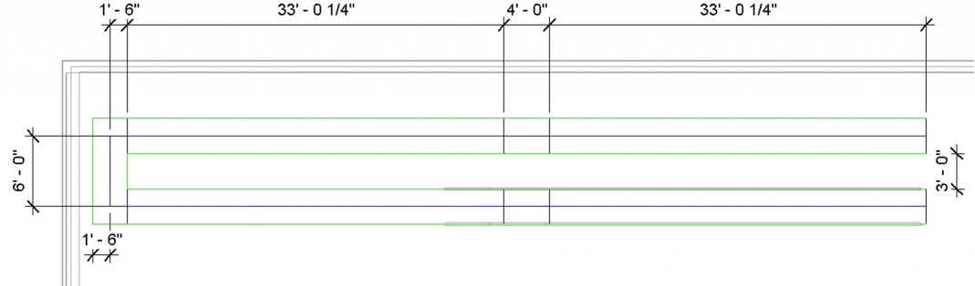
Figure 4.17 Ramp dimensions modified and shown in plan view - Use the Pin tool
 to lock the lines in place once the dimensions are corrected
 - Click the green checkmark to complete the ramp
- Select the ramp
- Click the Edit Type button
- Under construction, next to Shape, click the drop-down menu
- Choose Solid
- Use the Move tool to move the ramp into the corner as shown in Figure 4.18
- Select the railings
- Use the type selector to choose Handrail – Pipe
- Select and modify the Level 3 floor around the ramp
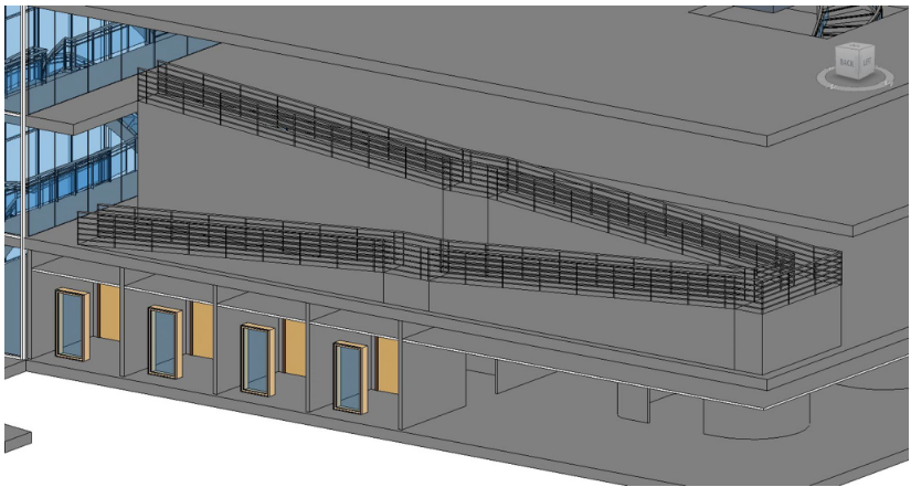
Figure 4.18 Completed ram shown in 3D view with 2 walls hidden
TIP