
16: Structural Systems
- Page ID
- 88776

16.1 SET UP A STRUCTURAL PROJECT AND LINK AN ARCHITECTURAL FILE
- Open the Revit application
- In the Revit Home Page click New
- In the New Project window use the drop-down menu to choose the Systems Template
- Choose to create a new Project
- Click OK
- Go to File then Save As
- Save the project in a known location under the name Class Project 1 Structural Concrete_Last First
- Go to the Insert tab and click the Link Revit icon

- Link the Class Project 1_Last First.rvt file then click Open
- Select the linked file and Pin
 the file to the canvas
 - Go to the Project Browser and open any elevation view
- The linked Revit file levels show but are not accessible. The structural template default levels may be hidden behind the linked file. Select a level then click and drag the hollow circle out to the right as shown in Figure 16.1
- Adjust Level 2 height to align to the bottom of the floor slab also shown in Figure 16.1
- In the Architecture tab use the Level icon to add Level 3, 4, and Roof. Rename any levels as necessary but do not change the names of corresponding views
- Make one last level at -5’0” and rename this T.O. Footing
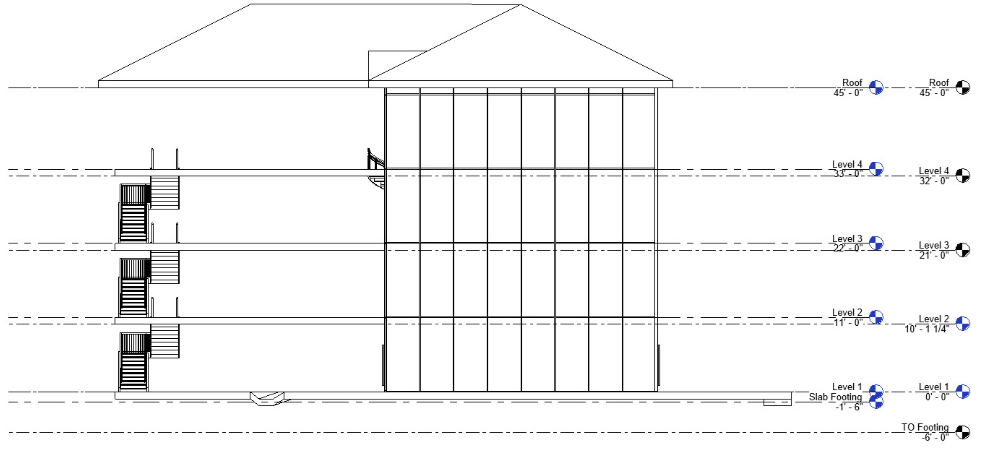
Figure 16.1 Levels added to the Structural file
16.2 PLACE STRUCTURAL GRIDS
- In the Level 1 floor plan view, change the visual style to hidden line and the detail level to fine.
- Go to the Structural tab, under the Datum panel, select the Grid icon

- On the Draw panel choose the pick lines tool

- On the Options Bar change the Offset to 1’6”
- Select the 7 exterior walls as shown in Figure 16.2 so grids lines are placed on the interior spaces
- Press escape twice to end the grid command
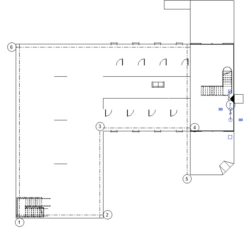
Figure 16.2 Seven placed grids using the pick lines tool shown in Level 1 floor plan view - Select a grid then click and drag the grips away from the building as shown in Figure 16.3. Repeat this step until the ends of all 7 grids are aligned.
- Select each grid then check or uncheck the boxes at the end of the grids to turn on and off the bubbles to match what is shown in 16.3
TIP
Grips are hollow blue circles located at the end of each grid used to change the length. The boxes at the end of each grid line will turn on and off the bubble annotation
- Place the remaining grids and use dimensions strings to correct spans as necessary
- Rename the horizontal grids by number and the vertical grids using letters
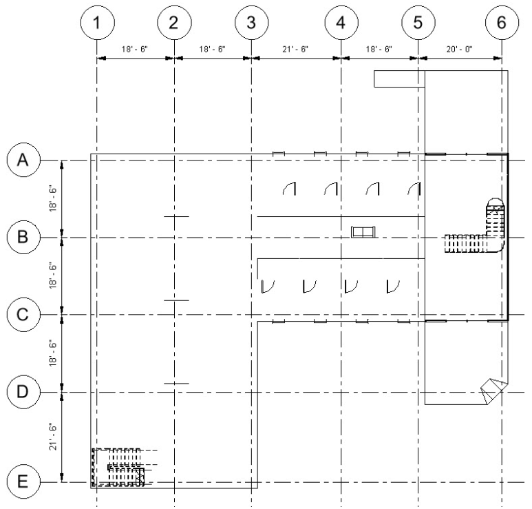
Figure 16.3 Completed grid lines placement, renaming, and dimensioning shown in Level 1 floor plan
TIP
If the dimensions are too hard to read, change the scale located on the View Control Bar.
16.3 PLACE FOUNDATION WALLS
- This section may be easier to complete with the Grid lines temporarily hidden. To do this select any grid
- On the View Control Bar, select the Temporary Hidden/Isolate icon
 – then chose Hide Category
 - On the Structures tab, click the Wall: Structural icon

- In the Properties Palette use the Type Selector to find Foundation – 12” Concrete
- Click the Edit Type button
- In the Type Properties window select Duplicate
- Rename it 3’0” Concrete
- Next to Structure select the Edit… button
- In the Edit Assembly window change the thickness to 3’0”
- Click OK to close out of both windows
- On the Ribbon choose the Pick lines tool
- On the Option Bar change the following parameters
- Depth: TO Footing
- Location line: Finish Face: Interior
- Offset: 0’6”
- Hover over an exterior wall until the dashed blue line is on the interior side of the line. Click to place the wall.
- Do this for each exterior lines as shown highlighted in yellow in Figure 16.4 – Use any other tools necessary to complete this task
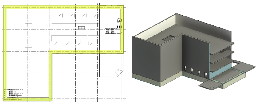
Figure 16.4 Foundation walls highlighted, shown in Level 1 floor plan view (left) and 3D view (right)
- Open the 3D view
- In the Properties Palette change Discipline to Coordination
- On the View Control Bar change to a Detailed level and Realistic Visual Style
16.4 PLACE BEARING FOOTING
- Go to the View tab
- Use the Plan View drop down to select Structural Plan
- In the New Structural Plan window select TO Footing and click OK
- Go to the Structure tab
- Select the Wall: Structure icon
- In the Properties Palette click the Edit Type button
- Select Duplicate then rename this element Bearing Foot 4’0”X2’0”
- Next to Structure click the Edit… button
- Change the thickness to 4’0”
- Click OK to close both windows
- On the Options Bar change the following Parameters
- Depth: Unconnected at 1’0”
- Location Line: Wall Centerline
- Offset: 0’0”
- In the Properties Palette Change the Base Offset to -1’0”
- Hover the cursor over a foundation wall then press the tab key until all the foundation walls are highlighted. Click once to place all bearing footings.
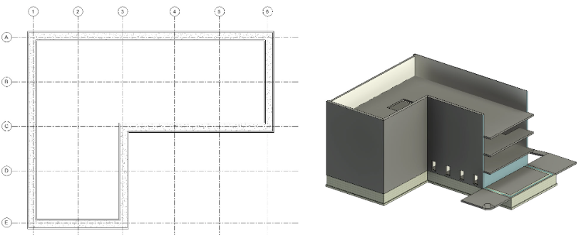
Figure 16.5 bearing Footing walls shown in plan view (left) and 3D view (right)
16.5 PLACE CONCRETE PIERS AND PILASTERS
- In the TO Footing plan view go to the Structure tab
- Click the Column icon

- Use the Type Selector to choose the 12X18 Column
- Click the Edit Type button
- Duplicate the element and name it 2’0”X2’0” then click OK
- In the Type Properties window change the b value to 2’0” and the h value to 2’0” then click OK
- On the Option bar change the following parameters
- Depth to Height
- Unconnected to Roof
- Place a column at the intersection of Grid 1 and Grid A
- On the Ribbon select the At Grids icon

- Click and drag to select all the grid lines
- Click the green
 checkmark to finish
 - Select and delete any unnecessary columns
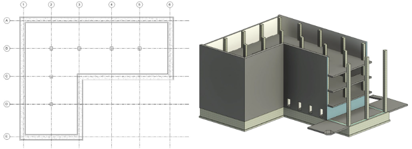
Figure 16.6 Placed columns shown in plan view (left) and 3D view (right) - In the Level 1 view, go to the Structures tab, under the Foundation panel, select the Isolated icon

- In the Properties Palette click the Edit Type button
- Duplicate the element and name it 4’0”x4’0”x1’0”
- Change the following parameters
- Foundation Thickness: 1’0”
- Width: 4’0”
- Length: 4’0”
- Then click OK
- On the Ribbon, select the At Columns icon

- Click and drag to highlight all the columns
- Click the green checkmark to finish
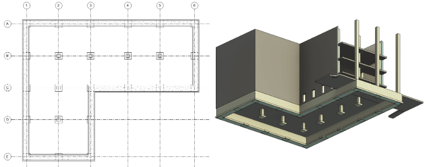
Figure 16.7 Completed Columns and Pilasters shown in Plan view (left) and 3D view (right – worms eye view – underneath the model looking up)
- Save the project and close the Structural Concrete file
16.6 PLACE STEEL COLUMNS
- Repeat the following sections for a new file
- 16.1 to create a new Structural project and name this file Class Project 1 Structural Steel_Last First
- 16.2 Place Structural Grids
- 16.3 Place Foundation Walls
- 16.4 Place Bearing Footings
- In Level 1 Plan view, go to the Structures tab and click the Column icon
- Select the 2’0”x2’0” Concrete Column
- On the Option Bar change Level to TO Footing with a Depth unconnected for 8’0”
- Click to place a column on the intersection of Grid 2 and Grid B
- On the Ribbon select the At Grids icon
- Click and drag to select all the grid lines
- Click the green checkmark to finish
- Select and delete any unnecessary columns
- Go to the Structures tab, under the Foundation panel, select the Isolated icon
- Select the 4’0”x4’0”x1’0” bearing footing
- On the Ribbon, select the At Columns icon
- Click and drag to highlight all the columns
- Click the green checkmark to finish
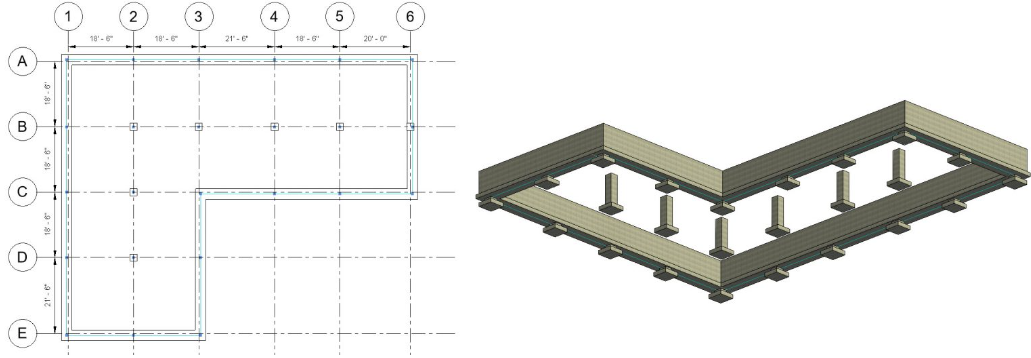
Figure 16.8 Concrete Piers and Pilasters shown in Plan view (left) 3D view (right – underneath the model looking up)
- Open the Level 1 plan view
- In the Properties Palette, click on the Edit… button next to Visibility/ Graphics Override
- Go to the Revit Links tab then uncheck the box to the left of the Architecture class file
- Click OK
- Go to the Structures tab and click the Column icon
- Select the Load Family icon

- Follow this folder directory
- English Imperial, Structural Columns, Steel, AISC 14.1, HP Shapes – Column.rfa
- The Specify Types window will appear. Choose the HP 8×36
- On the Option Bar change the height to Roof
- Place a column at the intersection of Grid 1 and Grid A
- On the Ribbon select the At Grids icon
- Click and drag to select all the grid lines
- Click the green checkmark to finish
- Select and delete any unnecessary columns
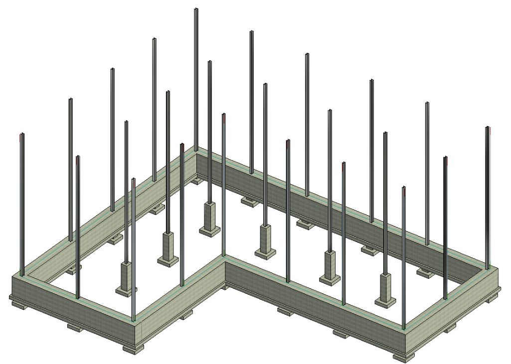
Figure 16.9 Steel columns placed shown in 3D view
16.7 PLACE PERIMETER FRAMING
- Open the Level 2 plan view
- Go to the Structure tab and select the Beam icon
- Use the Type Selector to choose the W12X26
- On the Ribbon make sure the Tag On Placement is selected

- On the Option Bar make sure the box next to Chain is checked
- Click the midpoint on the column at 1/A, drag the cursor to the midpoint on the column at 2/A and click again
- Continue this chain along the exterior columns as shown in Figure 16.10
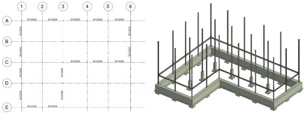
Figure 16.10 Perimeter beams placed along exterior columns shown in plan (left) and 3D view (right)
- Use the Type Selector to chose the W8X10 beam
- Now add beams in across the interior of the building as shown in Figure 16.11
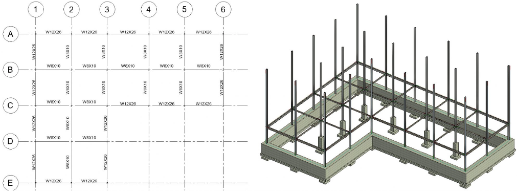
Figure 16.11 Interior Beam System placed on interior grid shown in Plan View (left) and in 3D view (right)
- In the 3D view, select an 8×10 beam
- Right click, Select all Instances, then choose In Entire Project
- On the Ribbon, click the Copy Icon

- Click the Paste drop down arrow then choose Align to Selected Levels

- In the window, press and hold the Control key down to select Levels 3, 4, and Roof
- Click OK
- Repeat the Copy and Paste to selected level steps for the 12×26 beam
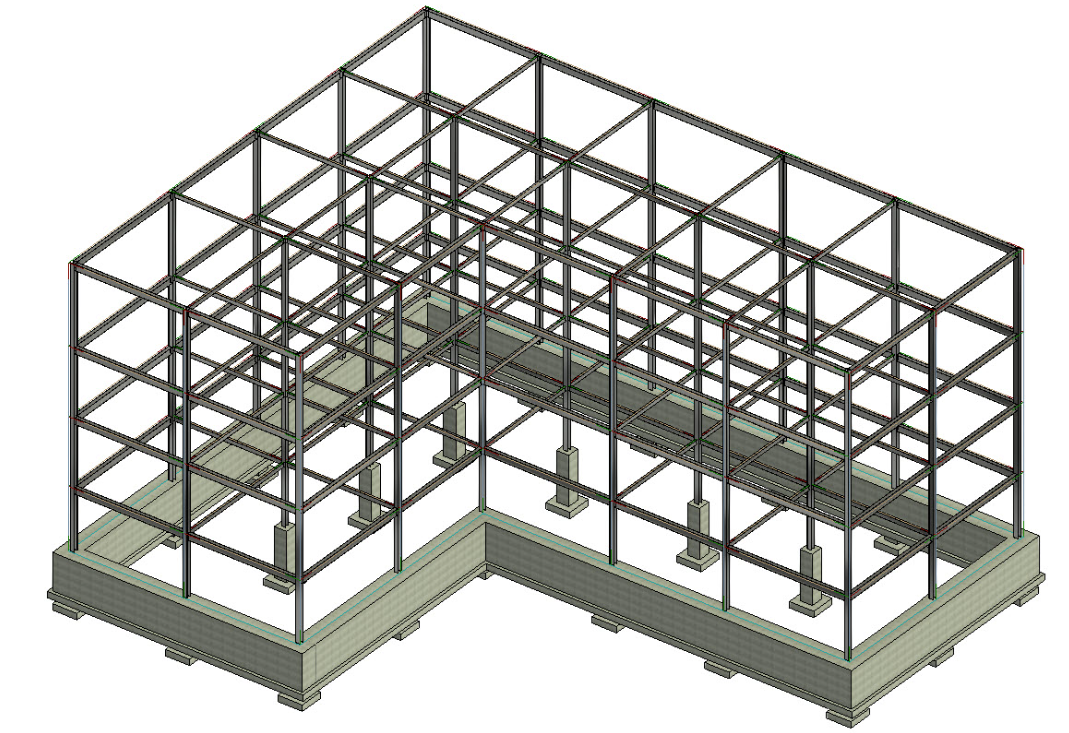
Figure 16.12 Perimeter beams placed on each level shown in Plan View
16.8 PLACE BEAM SYSTEM
- In the Level 2 Floor Plan view, go to the Structure tab and select the Beam System icon

- In the Properties Palette change the following parameters
- Beam Type: W Shapes: W12x36
- Layout Rule: Max Spacing
- Maximum Spacing: 4’0”
- On the Ribbon, make sure the Tag On Placement icon is selected
- Hover over the W12x26 beam between Grids 1/B and 2/B
- Click to place the system
- Continue this until all systems are placed
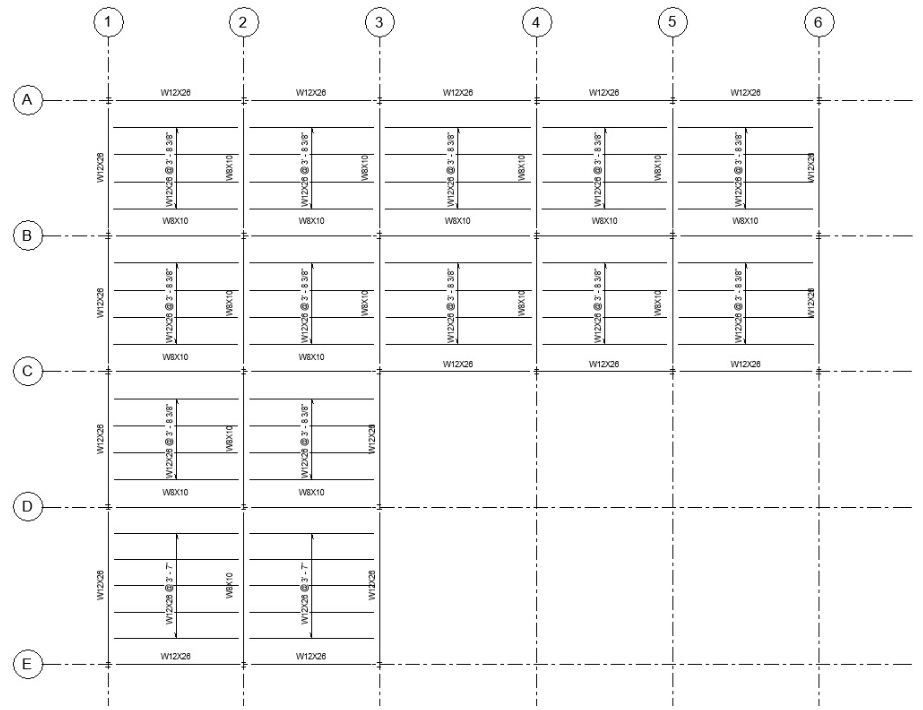
Figure 16.13 Beam Systems placed shown in Plan View (Shown in 1/18”=1’ scale so annotations don’t overlap)
- Hover over the edge of one of the beam systems and select it
- Right-click, Select all Instances, then choose In Entire Project
- On the Ribbon, click the Copy Icon
- Click the Paste drop-down arrow then choose Align to Selected Levels
- In the window, press and hold the Control key down to select Levels 3 and 4
- Click OK
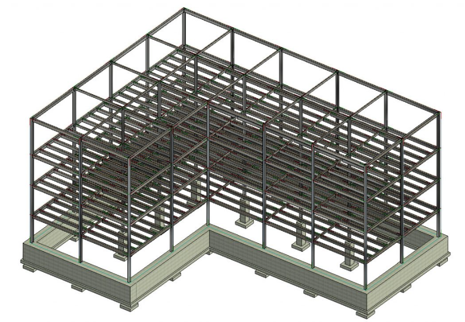
Figure 16.14 Beam System placed on level 3 and 4, shown in 3D view
16.9 PLACE JOIST SYSTEMS
- Go to the View tab
- Use the Plan View drop down to select Structural Plan
- In the New Structural Plan window select Roof and click OK
- In the Roof View, select all vertical beams by holding down the Shift key
- In the Properties Palette, change the z Offset Value to -0’5”
- Click Apply
- Go to the Insert tab, then select the Load Family icon
- Follow this folder directory
- English Imperial, Structural Framing, LH-Series Bar Joist.rfa
- The Specify Types window will appear. Choose the 18LH02
- Go to the Structure tab then select the Beam System icon
- On the Option bar change the following parameters
- Beam Type: 18LH02
- Check the box by 3D
- Hover over the beams and place the system in the same horizontal direction
- Go to the 3D view to verify the joists sit on the beams
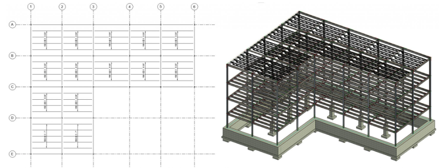
Figure 16.15 Joist systems placed shown in Plan View (left) and in 3D view (right)