
15: MEP - Fire Protection and Fabrication Parts


- Last updated
- Oct 19, 2022
- Save as PDF

( \newcommand{\kernel}{\mathrm{null}\,}\)
15.1 SET UP A MECHANICAL PROJECT AND LINK AN ARCHITECTURAL FILE
- Open the Revit application
- In the Revit Home Page click New
- In the New Project window use the drop-down menu to choose the Systems Template
- Choose to create a new Project
- Click OK
- Go to File then Save As
- Save the project in a known location under the name Class Project 1 MEP_Last First
- Go to the Insert tab and click the Link Revit icon

- Link the Class Project 1_Last First.rvt file then click Open
- Select the linked file and Pin
 the file to the canvas
 - Go to the Project Browser and expand Mechanical
- Expand the Mechanical Elevations
- Double click to open any elevation view
- The linked Revit file levels show but are not accessible. The mechanical template default levels are hidden behind the linked file. Click the Level 2 at the 10’0” height then click and drag the hollow circle out to the right as shown in Figure 15.1.
- Adjust the Level 2 height to 11’0” to match the linked file
- In the Architecture tab use the Level icon to add Level 3 and Level 4. Rename them Level 3 and 4 respectively but do not change the names of corresponding views.
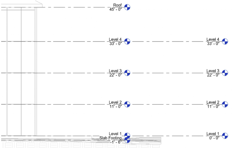
Figure 15.1 Levels added to the Mechanical file - In the Project Browser under the “???” category, expand the Ceiling Plans.
- Select one of the Ceiling Plans
- In the Properties Palette next to Sub-Discipline, type Fire Protection. For the remaining ceiling plan, use the drop-down arrow and select Fire Protection. When a sub-discipline is changed, its’ location in the project browser also changes. Notice how these views are now under the new Fire Protection category.
- Rename the views by their level #, plan type, and Mechanical type. A window will appear asking to change the corresponding views, select No.
- 3 – Ceiling FP
- 4 – Ceiling FP
- In the Project Bowser under Mechanical/HVAC/Ceiling Plans, select 1 – Ceiling Mech and change the Sub-Discipline to Fire Protection.
- Rename the view to replace the Mech with FP as shown in Figure 15.2
TIP
If one or more plans do not allow the sub-discipline to be changed follow these steps. Select the plan, click the Edit type button from the project browser, select the Mechanical Plan button, under the View properties section, scroll down then modify the Sub-Discipline located here. Click Apply then OK to close all windows. Lastly, rename the views.
- Repeat these steps for all the Floor Plans located under the HVAC category.
- Rename the plan views by their level #, plan type, mechanical type as shown in Figure 15.2, but do not change the corresponding views
- Change the {3D} view Sub-Discipline to Fire Protection
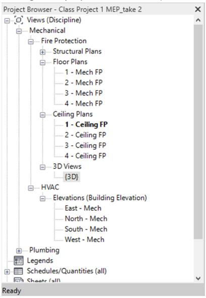
Figure 15.2 Created floor and ceiling plans are shown in the Project Browser - Open the first floor Fire Protection plan from the project browser
- In the Properties Palette click the Edit button next to View Range and change the Bottom and View Depth to Unlimited
- Click OK to close the window
- In the Properties Palette click the Visibility/Graphics Override button
- Use the Filter List drop-down menu to check the boxes next to Mechanical and uncheck the other options
- Scroll down to the bottom of the Visibility list and make sure Parts are checked
- Click OK to close the window
15.2 SET UP FIRE PROTECTION TYPES
- In the Systems tab, click the Pipe icon

- In the Properties Palette click the Edit Type button
- Click Duplicate
- Name it “Sprinkler System”
- Click the Edit button next to Routing Preferences
- Click the Load Family button
- Navigate the following folder path: Pipe/Fittings/Malleable Iron/Class 300/Threaded
- Select all of the files using the SHIFT key
- Once all are highlighted, click Open
- Under Pipe Segment select the Copper K option
- Use the green
 sign on the left to add a row under Pipe Segment
 - In the Routing Preferences window change each Content and sizes as shown in Figure 15.5, then click OK to close all windows
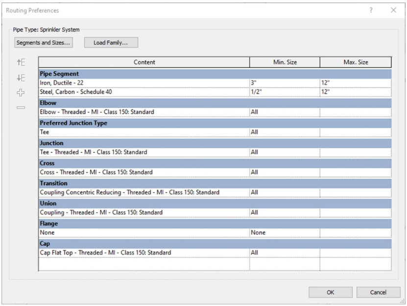
Figure 15.3 Routing Preferences selected content and sizes
15.3 ADD SPRINKLER HEADS
- In the Project Browser under Mechanical/Fire Protection/Ceiling Plans open the 1 – Ceiling FP view
- Click the Systems tab
- Click the Sprinklers icon

- Use the Type Selector to choose the ¾” Pendent
- Click the Place on Face icon

- Place one sprinkler at the center of a ceiling tile nearest the center of the room as shown in Figure 15.3
- Click the View tab then select the Section icon

- Place a section mark in front of the sprinkler head that was just placed, as shown in Figure 15.3
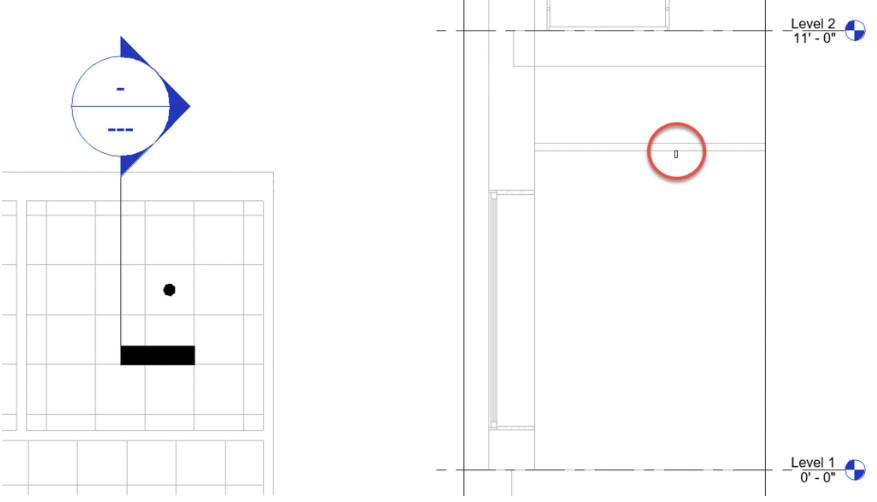
Figure 15.4 First sprinkler placed (left) and section cut view (right) - Place sprinklers in 6 more of the rooms as shown in Figure 15.4. The 8th room will become the Fire Riser room.
TIP
When copy/pasting repeating items, use the Copy tool and make sure the Multiple option is checked. Select multiple items by holding the SHIFT key down.
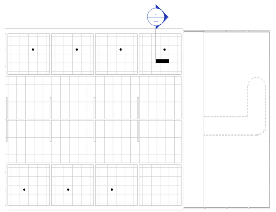
Figure 15.5 Seven placed sprinklers in the ceiling plan view
15.4 Add Sprinkler mains and branch lines
- Open the Mechanical/Fire Protection/Floor Plans/1 – Mech FP view from the project browser
- In the Systems tab, click the Pipe icon
- On the Options Bar change the diameter to 12 inches and the middle elevation to -1’0”
- Draw a short length of pipe on the exterior of the 8th room as shown in Figure 15.6.
TIP
If ESC is clicked by accident right-click the pipe and click Draw Pipe to begin again
- Reduce the diameter to 8” and draw a pipe to just inside the exterior wall
- Change the Offset to 9’0”
- Draw the Pipe across and down the center of the room as shown in Figure 15.6
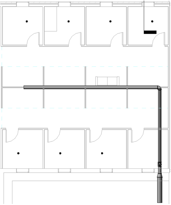
Figure 15.6 Initial main pipe drawn with 12” to 8” diameterTIP
The Detail level: fine and visual style: shaded shows the element render. The Detail level: course and visual style: Hidden Line will show the 2D symbol annotation as typically seen in construction documentation.
- Change the diameter to 4” and draw a pipe into each room just past the walls as shown in Figure 15.7
- Change the diameter to 1-1/2” and draw a pipe just past the sprinkler head as shown in Figure 15.7
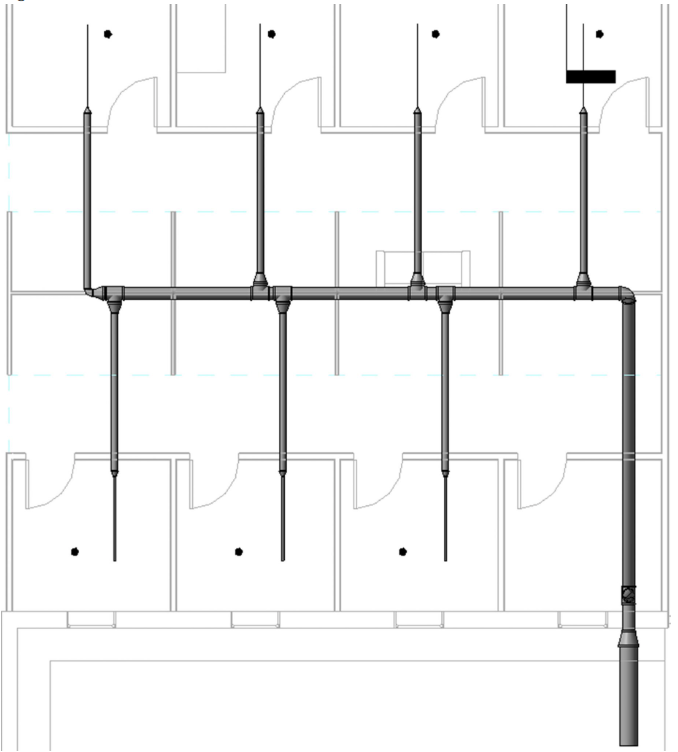
Figure 15.7 Reduction of pipes using diameters of 4” and 1-1/2” - Draw a 1 ½” diameter pipe out towards the sprinkler head as shown in Figure 15.8
- Change the offset to 9’6” and change the diameter to ¾”
- Draw a pipe from the 1/12” pipe to the center of the sprinkler and Revit will connect it automatically. See Figure 15.8 for reference.

Figure 15.8 Pipe main and branch lines connected to the sprinkler head shown in 2D plan view (left) and in 3D view (right)
15.5 ADD PIPE FITTINGS, VALVES, AND FIRE DEPARTMENT INLETS
- Go to the Systems tab
- Click the Pipe Fittings icon

- Use the Type Selector to choose the Cap – Threaded – MI – Class 300 Standard
- Hover the cursor over the end of the pipe that runs past the sprinkler. When the endpoint highlights click once to place the cap as shown in Figure 15.9
- Cap the end of all 6 pipes
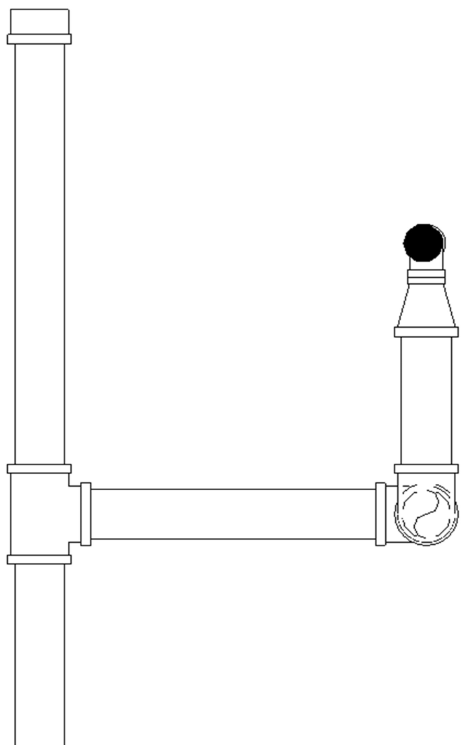
Figure 15.9 Cap placed on the end of the branch pipe shown in plan view (with the hidden line style selected) - Go to the Systems tab
- Click the Pipe Accessory icon

- A message window will prompt to load a family. Select yes. If this message does not appear then click the Load Family icon

- Follow the file path: Pipe/Valve/Backflow preventers
- Choose the Double Check Valve 2.5-10in and click Open
- Use the Type Selector to choose the 8” Double Check Valve. Adjust the main pipe to fit the accessory before the 9’0” offset. See Figure 15.10 for reference.
TIP
The 9’ offset may need to be moved to fit the Valve. Select the vertical pipe and use the move tool to adjust room. The option bar may be used to check “Rotate after placement” if the pipe is showing the wrong direction.
- In the Systems tab click the Mechanical Equipment icon

- Click the Load Family icon
- Follow the file path: Fire Protection/Connections
- Choose the Fire Department Inlet Connection – 3-way flush plate
- Place the element on the exterior face of the exterior wall as shown in Figure 15.10
- Select the flush plate element
- Click THE blue
 sign that appears farthest away from the flush plate
 - On the Options Bar make sure the diameter is set to 2 ½” and the offset is 2’4”
- Draw a pipe to just inside the wall
- Change the offset to 9’0” and draw a pipe out then to the right to connect with the main line as shown in Figure 15.10
- Complete steps 17 through 21 for the remaining 2 inlet connections
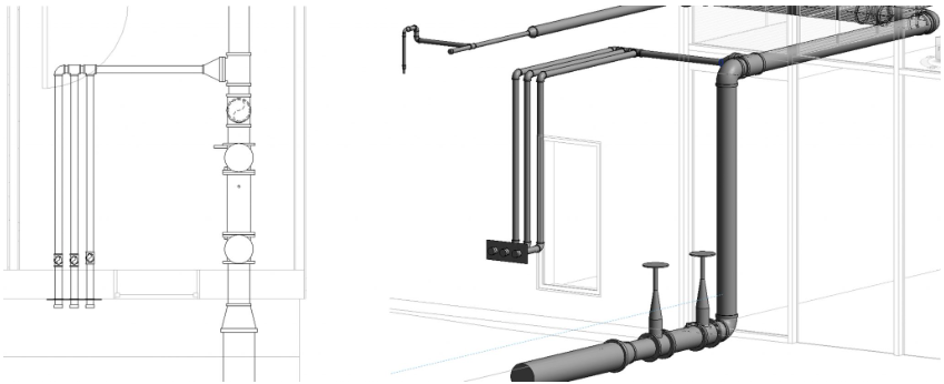
Figure 15.10 Common pipe accessories added to the fire protection system in 2D plan view (left) and 3D view (right)
15.6 ADD FIRE SYSTEM COMPONENTS AND CIRCUITS
- Go to the Insert tab
- Click on the Load Family icon
- Follow the file path: Electrical/MEP/Information and Communication/Fire Alarm
- Hold the Control key down and select Fire Alarm Control Panel, Fire Alarm Horn Strobe – Ceiling Mounted, Manual Pull Station, and Smoke Detector then click Open
- Go to the Ceiling plan
- Click on the Systems tab
- Click the Device icon
 drop-down menu then click the Fire Alarm icon
TIP
If the device does not appear in the plan view, access the Visibility/Graphics Override and make sure the Electrical Equipment, Electrical Fixtures and Fire Alarm Devices boxes are checked
- Change the Type Selector to Fire Alarm Horn Strobe – Ceiling Mounted
- Click the Place on Face icon then place the alarm near the center of the room
- Change the Type Selector to Plain Smoke Detector
- Click the Place on Face icon then place the smoke detector near the center of the room
- In the Systems tab click the Electrical Equipment icon

- Place the Fire Alarm Control Panel inside the adjacent room where the pipe inlets are located
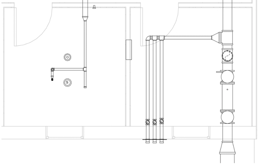
Figure 15.11 Fire alarm devices placed in plan view - Select the Horn Strobe device
- Click the Fire Alarm icon

- Click the Edit Circuit icon

- On the ribbon choose Panel: 16X19
- Hold down the Control key and select the Smoke Detector and Manual Pull alarm
- In the Properties Palette change the Load Name to Office 107 Fire Alarm
- Click the green
 checkmark to finish the Circuit
 - Repeat steps 13 through 19 to add fire alarm devices and circuits to the remaining 6 offices. Use the room tag Figure 8.7 to change the Load Name.
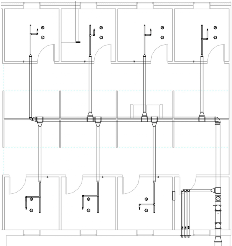
Figure 15.12 Placed fire alarm devices in plan view
15.7 ANNOTATE ELEMENTS
- Click the Annotate tab
- Click the Tag by Category icon
- Click the pipe to start the leader
- Drag the cursor up and to the left and click
- Then drag the cursor to the left and click to finish the leader tag
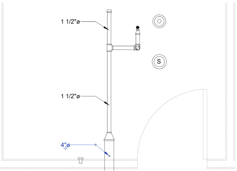
Figure 15.13 Tag by category to annotate pipe diameters
15.8 FABRICATION OF PARTS
Equipment parts with specific fabrication parameters are available to download and upload into Revit to design accurate MEP systems.
15.9 LOADING IMPERIAL PARTS
- In the Systems tab click the Fabrication Part icon
 to open the MEP menu
 - In the lower right corner click the Settings.. button
- Under Fabrication Configuration use the drop-down to choose Revit MEP Imperial Content
- Select all the items in the left-field then click the Add button

- Click OK
15.10 ADD AND CONVERTING REVIT SYSTEMS INTO FABRICATION PARTS
- In the Systems tab click the Duct icon

- On the Options Bar change the Height to 6” and the offset to 8’6”
- Draw ductwork similar to what is shown in Figure 15.14
- Select all of the ductwork then click the Design to Fabrication icon

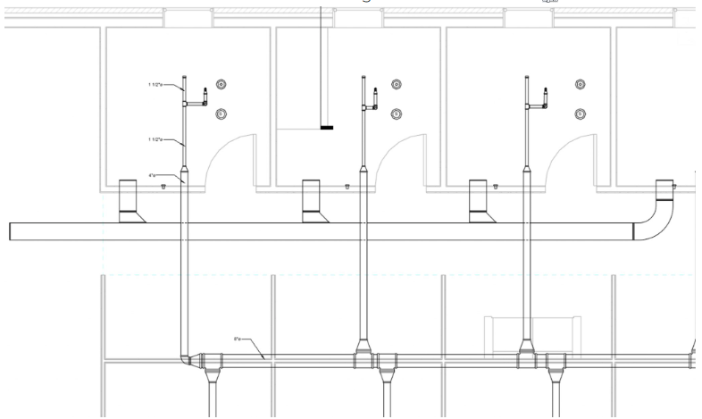
Figure 15.14 Fabricated ductwork shown in plan view - Select the main duct that runs along the corridor. The HVAC industry does not make ductwork continuous as this is shown. Click the Optimize Length icon

- In the MEP Fabrication Parts window select the Service: Ductwork: -2in WG
- Scroll to the bottom and select the End Cap S&D
- Hover the cursor of the left end of the duct where the red arrow is located. When the endpoint snap appears click to place the end cap.
- In the MEP Fabrication Parts window select the Group: Hangers
- Select the Strut Hanger and place 2 hangers for each section of ductwork
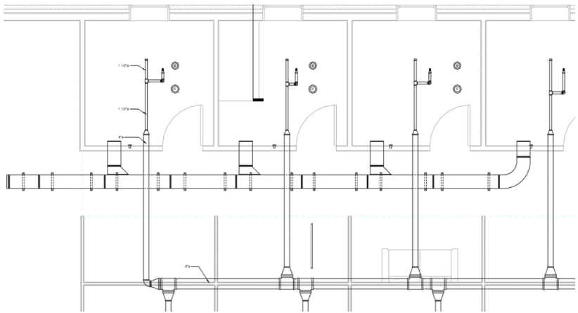
Figure 15.15 Ductwork with optimized length adjustments and strut hangers
15.11 BUILD FROM FRABRICATION PARTS
- In the MEP Fabrication Part window change the Service: Ductwork +2 WG and Group: Rnd
- Select the Spiral Pipe and change the diameter to 12” and the offset to 9’0” in the properties palette
- In the 1 – Mech FP view place a line of round ducts along the first floor open workspace as shown in Figure 15.16
- Use the Mitered Elbow to turn the pipes up at a 90-degree angle
- In the 3D view place another straight duct
- Place another mitered elbow to turn above the second floor
- In the 2 – Mech FP continue to draw pipes across the second floor open workspace. Make sure the offset it 9’ 0”
- Select the Tee part and equally place three to face in toward the space
- Select the Straight part and connect ductwork from the Tee’s
- Place endcaps at the ends of the ductwork and a series of Conical caps to distribute air. See Figure 15.16 for reference.
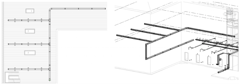
Figure 15.16 Round ductwork shown in 2 – Mech FP and in 3D view