2.4.3 Thermoelectric Effects
- Page ID
- 2771
\( \newcommand{\vecs}[1]{\overset { \scriptstyle \rightharpoonup} {\mathbf{#1}} } \)
\( \newcommand{\vecd}[1]{\overset{-\!-\!\rightharpoonup}{\vphantom{a}\smash {#1}}} \)
\( \newcommand{\id}{\mathrm{id}}\) \( \newcommand{\Span}{\mathrm{span}}\)
( \newcommand{\kernel}{\mathrm{null}\,}\) \( \newcommand{\range}{\mathrm{range}\,}\)
\( \newcommand{\RealPart}{\mathrm{Re}}\) \( \newcommand{\ImaginaryPart}{\mathrm{Im}}\)
\( \newcommand{\Argument}{\mathrm{Arg}}\) \( \newcommand{\norm}[1]{\| #1 \|}\)
\( \newcommand{\inner}[2]{\langle #1, #2 \rangle}\)
\( \newcommand{\Span}{\mathrm{span}}\)
\( \newcommand{\id}{\mathrm{id}}\)
\( \newcommand{\Span}{\mathrm{span}}\)
\( \newcommand{\kernel}{\mathrm{null}\,}\)
\( \newcommand{\range}{\mathrm{range}\,}\)
\( \newcommand{\RealPart}{\mathrm{Re}}\)
\( \newcommand{\ImaginaryPart}{\mathrm{Im}}\)
\( \newcommand{\Argument}{\mathrm{Arg}}\)
\( \newcommand{\norm}[1]{\| #1 \|}\)
\( \newcommand{\inner}[2]{\langle #1, #2 \rangle}\)
\( \newcommand{\Span}{\mathrm{span}}\) \( \newcommand{\AA}{\unicode[.8,0]{x212B}}\)
\( \newcommand{\vectorA}[1]{\vec{#1}} % arrow\)
\( \newcommand{\vectorAt}[1]{\vec{\text{#1}}} % arrow\)
\( \newcommand{\vectorB}[1]{\overset { \scriptstyle \rightharpoonup} {\mathbf{#1}} } \)
\( \newcommand{\vectorC}[1]{\textbf{#1}} \)
\( \newcommand{\vectorD}[1]{\overrightarrow{#1}} \)
\( \newcommand{\vectorDt}[1]{\overrightarrow{\text{#1}}} \)
\( \newcommand{\vectE}[1]{\overset{-\!-\!\rightharpoonup}{\vphantom{a}\smash{\mathbf {#1}}}} \)
\( \newcommand{\vecs}[1]{\overset { \scriptstyle \rightharpoonup} {\mathbf{#1}} } \)
\( \newcommand{\vecd}[1]{\overset{-\!-\!\rightharpoonup}{\vphantom{a}\smash {#1}}} \)
\(\newcommand{\avec}{\mathbf a}\) \(\newcommand{\bvec}{\mathbf b}\) \(\newcommand{\cvec}{\mathbf c}\) \(\newcommand{\dvec}{\mathbf d}\) \(\newcommand{\dtil}{\widetilde{\mathbf d}}\) \(\newcommand{\evec}{\mathbf e}\) \(\newcommand{\fvec}{\mathbf f}\) \(\newcommand{\nvec}{\mathbf n}\) \(\newcommand{\pvec}{\mathbf p}\) \(\newcommand{\qvec}{\mathbf q}\) \(\newcommand{\svec}{\mathbf s}\) \(\newcommand{\tvec}{\mathbf t}\) \(\newcommand{\uvec}{\mathbf u}\) \(\newcommand{\vvec}{\mathbf v}\) \(\newcommand{\wvec}{\mathbf w}\) \(\newcommand{\xvec}{\mathbf x}\) \(\newcommand{\yvec}{\mathbf y}\) \(\newcommand{\zvec}{\mathbf z}\) \(\newcommand{\rvec}{\mathbf r}\) \(\newcommand{\mvec}{\mathbf m}\) \(\newcommand{\zerovec}{\mathbf 0}\) \(\newcommand{\onevec}{\mathbf 1}\) \(\newcommand{\real}{\mathbb R}\) \(\newcommand{\twovec}[2]{\left[\begin{array}{r}#1 \\ #2 \end{array}\right]}\) \(\newcommand{\ctwovec}[2]{\left[\begin{array}{c}#1 \\ #2 \end{array}\right]}\) \(\newcommand{\threevec}[3]{\left[\begin{array}{r}#1 \\ #2 \\ #3 \end{array}\right]}\) \(\newcommand{\cthreevec}[3]{\left[\begin{array}{c}#1 \\ #2 \\ #3 \end{array}\right]}\) \(\newcommand{\fourvec}[4]{\left[\begin{array}{r}#1 \\ #2 \\ #3 \\ #4 \end{array}\right]}\) \(\newcommand{\cfourvec}[4]{\left[\begin{array}{c}#1 \\ #2 \\ #3 \\ #4 \end{array}\right]}\) \(\newcommand{\fivevec}[5]{\left[\begin{array}{r}#1 \\ #2 \\ #3 \\ #4 \\ #5 \\ \end{array}\right]}\) \(\newcommand{\cfivevec}[5]{\left[\begin{array}{c}#1 \\ #2 \\ #3 \\ #4 \\ #5 \\ \end{array}\right]}\) \(\newcommand{\mattwo}[4]{\left[\begin{array}{rr}#1 \amp #2 \\ #3 \amp #4 \\ \end{array}\right]}\) \(\newcommand{\laspan}[1]{\text{Span}\{#1\}}\) \(\newcommand{\bcal}{\cal B}\) \(\newcommand{\ccal}{\cal C}\) \(\newcommand{\scal}{\cal S}\) \(\newcommand{\wcal}{\cal W}\) \(\newcommand{\ecal}{\cal E}\) \(\newcommand{\coords}[2]{\left\{#1\right\}_{#2}}\) \(\newcommand{\gray}[1]{\color{gray}{#1}}\) \(\newcommand{\lgray}[1]{\color{lightgray}{#1}}\) \(\newcommand{\rank}{\operatorname{rank}}\) \(\newcommand{\row}{\text{Row}}\) \(\newcommand{\col}{\text{Col}}\) \(\renewcommand{\row}{\text{Row}}\) \(\newcommand{\nul}{\text{Nul}}\) \(\newcommand{\var}{\text{Var}}\) \(\newcommand{\corr}{\text{corr}}\) \(\newcommand{\len}[1]{\left|#1\right|}\) \(\newcommand{\bbar}{\overline{\bvec}}\) \(\newcommand{\bhat}{\widehat{\bvec}}\) \(\newcommand{\bperp}{\bvec^\perp}\) \(\newcommand{\xhat}{\widehat{\xvec}}\) \(\newcommand{\vhat}{\widehat{\vvec}}\) \(\newcommand{\uhat}{\widehat{\uvec}}\) \(\newcommand{\what}{\widehat{\wvec}}\) \(\newcommand{\Sighat}{\widehat{\Sigma}}\) \(\newcommand{\lt}{<}\) \(\newcommand{\gt}{>}\) \(\newcommand{\amp}{&}\) \(\definecolor{fillinmathshade}{gray}{0.9}\)So far we have only considered one conducting material; the unavoidable contacts between conductors, implicitly always required, were seemingly devoid of special properties.
- We know that this is not true for many other contacts; e.g. combinations of
- semiconductor - semiconductor.
- semiconductor - conductor.
- ionic conductor - conductor.
- What about metal - metal contacts?
We routinely solder wires of different conductors together or join them in any way, and do not worry about the contacts. Besides, maybe, a certain (usually small) contact resistance which is a property of the interface and must be added to the resistance of the two materials, there seems to be no other specific property of the contact.
- But that is only true as long as the temperature is constant in the whole system of at least two conductors.
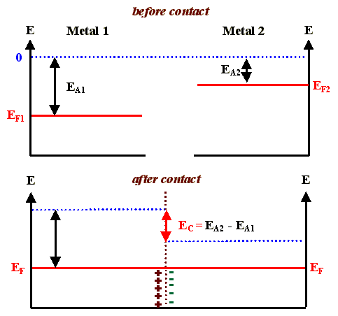
- The reason for this is that we always get a contact voltage, as in the case of semiconductors, but the extension of the charged layers at the interface (the Debye lengths) is so short that no specific phenomena result from this.
- Consider the band diagrams before and after joining two metals

We have a dipole layer of charges at the interface which, owing to the large carrier density, is extremely thin and does not hinder current flow (it is easy for electrons to tunnel through the potential barrier).
- We also have a contact potential, which is called the Volta potential. Since in any closed circuit (containing, e.g., the wires to the voltmeter), the sum of the Volta potentials must be zero in thermal equilibrium, it therefore can not be measured directly.
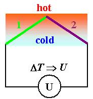
- If, however, one of the at least two contacts needed for a closed circuit is at a temperature T2 that is different from the temperature T1 of the first contact, we have non-equilibrium and now a voltage may be measured. We observe the Seebeck effect, one of several thermoelectric effects.
We will not go into details here (consult the link for this) but will only mention some applications and related effects.
Seebeck Effect
The Seebeck effect is the base for thermoelements or thermocouples, the standard device for measuring temperatures (the good old mercury thermometer is virtually nonexistent in technical applications, especially at high temperatures).
|
|
|
- Generally, the thermovoltage should be larger for couples of conductors with very different Fermi energies or carrier densities, since then the Volta potential is larger.
- Being more specific, the Volta potential should follow Nernsts law. But here we are only interested in the practical aspects of thermocouples.
For technically important materials, it is convenient to construct a voltage scale for thermocouples given in mV/100K.
- The voltage measured for a temperature difference of 100 K is then the difference of the two values given on that scale for the two materials joined in a thermocouple. The zero point was arbitrarily chosen for Pt.
| Bi | Ni | Pd | Pt | Hg | PtRh | Cu | Mo | Fe | NiCr | Sb |
| -7,7 | -1,5 | -0,3 | 0 | 0 | 0,7 | 0,77 | 1,2 | 1,92 | 2,6 | 4,8 |
- Useful couples are, e.g. Ni/NiCr, with a thermovoltage of ca. 4 mV/100K and a usable temperature range up to 1000 K.
The Seebeck effect, for many years extensively used for measuring temperatures, can also be used to convert heat energy directly into electrical energy. Thermoelectric generators are becoming an exciting field of materials science, because optimized materials, based on a thorough understanding of the requirements for power generation and the concomitant requirements for the materials, are becoming available.
Other Thermoelectric Effects
There are several thermoelectrical effects which are deeply routed in non-equilibrium thermodynamics. Essentially, there is a "reciprocating" coupling of gradients in driving forces and currents of any kind (not just electrical currents but also, e.g. particle currents, heat currents, or even entropy currents).
- Reciprocating means, that if a gradient - e.g. in the temperature - induces an electric current across a junction (the Seebeck effect), than an electric current induced by some other means must produce a temperature gradient. And this does not address the heating simply due to ohmic heating!
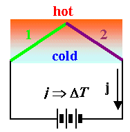
- The "reversed" Seebeck effect does indeed exist, it is called the Peltier effect. In our schematic diagram it looks like this:
 |
|
- The temperature difference ∆T between the two junctions due to the external current density j induced by the battery and the Peltier effect then is approximately given by
\[\Delta T\approx\text{const,}\cdot j\]
- The removal of heat or thermal energy thus is linear with the current density
- But there is always heating due to by ohmic losses, too. This is proportional to j2, so it may easily overwhelm the Peltier effect and no net cooling is observed in this case.
The Peltier effect is not useful for heating - that is much easier done with resistance heating - but for cooling!
- With optimized materials, you can lower the temperature considerably at one junction by simply passing current through the device! The Peltier effect actually has been used for refrigerators, but now is mainly applied for controlling the temperature of specimens (e.g. chips) while measurements are being made.
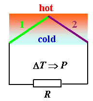
One can do a third thing with thermoelements: Generate power. You have a voltage coupled to a temperaturr difference, and that can drive a current through a load in the form of a resistor.
 |
Invariably the question of the efficiency η of power generation comes up. How much of the thermal energy in the system is converted to electrical energy? This is not easy to calculate in detail. It is, however, very easy to guess to what parameters η will be proportional:
|
If the thermal conductivity κ is large, you cannot maintain a thermal gradient for very long. If the electrical conductivity σ is small, you loose energy by heating the resistor. It is thus clear that the efficiency is proportional to σ/κ. The Seebeck coefficient S, finally, simply characterizes the materials to be used. Unfortunately, for most materials, a large σ implies a large κ - think of any metal, for example!
There is one more effect worthwhile to mention: If you have an external current and an external temperature gradient at the same time, you have the Thomson effect. But we mention that only for completeness; so far the Thomson effect does not seem to be of technical importance. Again, more information is contained in the link.


