3.1.1 Polarization and Dielectric Constant
- Page ID
- 2864
\( \newcommand{\vecs}[1]{\overset { \scriptstyle \rightharpoonup} {\mathbf{#1}} } \)
\( \newcommand{\vecd}[1]{\overset{-\!-\!\rightharpoonup}{\vphantom{a}\smash {#1}}} \)
\( \newcommand{\id}{\mathrm{id}}\) \( \newcommand{\Span}{\mathrm{span}}\)
( \newcommand{\kernel}{\mathrm{null}\,}\) \( \newcommand{\range}{\mathrm{range}\,}\)
\( \newcommand{\RealPart}{\mathrm{Re}}\) \( \newcommand{\ImaginaryPart}{\mathrm{Im}}\)
\( \newcommand{\Argument}{\mathrm{Arg}}\) \( \newcommand{\norm}[1]{\| #1 \|}\)
\( \newcommand{\inner}[2]{\langle #1, #2 \rangle}\)
\( \newcommand{\Span}{\mathrm{span}}\)
\( \newcommand{\id}{\mathrm{id}}\)
\( \newcommand{\Span}{\mathrm{span}}\)
\( \newcommand{\kernel}{\mathrm{null}\,}\)
\( \newcommand{\range}{\mathrm{range}\,}\)
\( \newcommand{\RealPart}{\mathrm{Re}}\)
\( \newcommand{\ImaginaryPart}{\mathrm{Im}}\)
\( \newcommand{\Argument}{\mathrm{Arg}}\)
\( \newcommand{\norm}[1]{\| #1 \|}\)
\( \newcommand{\inner}[2]{\langle #1, #2 \rangle}\)
\( \newcommand{\Span}{\mathrm{span}}\) \( \newcommand{\AA}{\unicode[.8,0]{x212B}}\)
\( \newcommand{\vectorA}[1]{\vec{#1}} % arrow\)
\( \newcommand{\vectorAt}[1]{\vec{\text{#1}}} % arrow\)
\( \newcommand{\vectorB}[1]{\overset { \scriptstyle \rightharpoonup} {\mathbf{#1}} } \)
\( \newcommand{\vectorC}[1]{\textbf{#1}} \)
\( \newcommand{\vectorD}[1]{\overrightarrow{#1}} \)
\( \newcommand{\vectorDt}[1]{\overrightarrow{\text{#1}}} \)
\( \newcommand{\vectE}[1]{\overset{-\!-\!\rightharpoonup}{\vphantom{a}\smash{\mathbf {#1}}}} \)
\( \newcommand{\vecs}[1]{\overset { \scriptstyle \rightharpoonup} {\mathbf{#1}} } \)
\( \newcommand{\vecd}[1]{\overset{-\!-\!\rightharpoonup}{\vphantom{a}\smash {#1}}} \)
\(\newcommand{\avec}{\mathbf a}\) \(\newcommand{\bvec}{\mathbf b}\) \(\newcommand{\cvec}{\mathbf c}\) \(\newcommand{\dvec}{\mathbf d}\) \(\newcommand{\dtil}{\widetilde{\mathbf d}}\) \(\newcommand{\evec}{\mathbf e}\) \(\newcommand{\fvec}{\mathbf f}\) \(\newcommand{\nvec}{\mathbf n}\) \(\newcommand{\pvec}{\mathbf p}\) \(\newcommand{\qvec}{\mathbf q}\) \(\newcommand{\svec}{\mathbf s}\) \(\newcommand{\tvec}{\mathbf t}\) \(\newcommand{\uvec}{\mathbf u}\) \(\newcommand{\vvec}{\mathbf v}\) \(\newcommand{\wvec}{\mathbf w}\) \(\newcommand{\xvec}{\mathbf x}\) \(\newcommand{\yvec}{\mathbf y}\) \(\newcommand{\zvec}{\mathbf z}\) \(\newcommand{\rvec}{\mathbf r}\) \(\newcommand{\mvec}{\mathbf m}\) \(\newcommand{\zerovec}{\mathbf 0}\) \(\newcommand{\onevec}{\mathbf 1}\) \(\newcommand{\real}{\mathbb R}\) \(\newcommand{\twovec}[2]{\left[\begin{array}{r}#1 \\ #2 \end{array}\right]}\) \(\newcommand{\ctwovec}[2]{\left[\begin{array}{c}#1 \\ #2 \end{array}\right]}\) \(\newcommand{\threevec}[3]{\left[\begin{array}{r}#1 \\ #2 \\ #3 \end{array}\right]}\) \(\newcommand{\cthreevec}[3]{\left[\begin{array}{c}#1 \\ #2 \\ #3 \end{array}\right]}\) \(\newcommand{\fourvec}[4]{\left[\begin{array}{r}#1 \\ #2 \\ #3 \\ #4 \end{array}\right]}\) \(\newcommand{\cfourvec}[4]{\left[\begin{array}{c}#1 \\ #2 \\ #3 \\ #4 \end{array}\right]}\) \(\newcommand{\fivevec}[5]{\left[\begin{array}{r}#1 \\ #2 \\ #3 \\ #4 \\ #5 \\ \end{array}\right]}\) \(\newcommand{\cfivevec}[5]{\left[\begin{array}{c}#1 \\ #2 \\ #3 \\ #4 \\ #5 \\ \end{array}\right]}\) \(\newcommand{\mattwo}[4]{\left[\begin{array}{rr}#1 \amp #2 \\ #3 \amp #4 \\ \end{array}\right]}\) \(\newcommand{\laspan}[1]{\text{Span}\{#1\}}\) \(\newcommand{\bcal}{\cal B}\) \(\newcommand{\ccal}{\cal C}\) \(\newcommand{\scal}{\cal S}\) \(\newcommand{\wcal}{\cal W}\) \(\newcommand{\ecal}{\cal E}\) \(\newcommand{\coords}[2]{\left\{#1\right\}_{#2}}\) \(\newcommand{\gray}[1]{\color{gray}{#1}}\) \(\newcommand{\lgray}[1]{\color{lightgray}{#1}}\) \(\newcommand{\rank}{\operatorname{rank}}\) \(\newcommand{\row}{\text{Row}}\) \(\newcommand{\col}{\text{Col}}\) \(\renewcommand{\row}{\text{Row}}\) \(\newcommand{\nul}{\text{Nul}}\) \(\newcommand{\var}{\text{Var}}\) \(\newcommand{\corr}{\text{corr}}\) \(\newcommand{\len}[1]{\left|#1\right|}\) \(\newcommand{\bbar}{\overline{\bvec}}\) \(\newcommand{\bhat}{\widehat{\bvec}}\) \(\newcommand{\bperp}{\bvec^\perp}\) \(\newcommand{\xhat}{\widehat{\xvec}}\) \(\newcommand{\vhat}{\widehat{\vvec}}\) \(\newcommand{\uhat}{\widehat{\uvec}}\) \(\newcommand{\what}{\widehat{\wvec}}\) \(\newcommand{\Sighat}{\widehat{\Sigma}}\) \(\newcommand{\lt}{<}\) \(\newcommand{\gt}{>}\) \(\newcommand{\amp}{&}\) \(\definecolor{fillinmathshade}{gray}{0.9}\)For the sake of simplicity we assume that dielectric materials are perfect insulators. In other words, there are no mobile charged particles.
We want now to be able to answer three questions:
- Given the atomic structure of the material - What is its dielectric constant (DK)?
- How does the DK depend on the frequency of the external field?
- How large is the maximum field strength a dielectric can take? Remember, no material can take arbitrarily large loads - mechanical, electrical, whatever.
For starters, we look at some general descriptions, definitions and general relations of the quantities necessary in this context.
The dielectric constant of solids is an interesting material parameter only if the material is exposed to an electrical field (and this includes the electrical field of an electromagnetic wave). The effect of the electrical field (or just field for short from now on) can be twofold:
- It induces electrical dipoles in the material and tries to align them in the field direction. In other words, with a field, dipoles come into being that do not exist without a field.
- It tries to align dipoles that are already present in the material. In other words, the material contains electric dipoles even without a field.
Of course we also may have a combination of both effects: The electrical field may change the distribution of existing dipoles while trying to align them, and it may generate new dipoles in addition.
The total effect of an electrical field on a dielectric material is called the polarization of the material.
To understand that better, lets look at the most simple object we have: A single atom (we do not even consider molecules at this point).
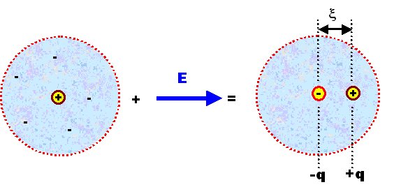
- We have a positively charged nucleus and the electron "cloud". The smeared-out negative charge associated with the electron cloud can be averaged in space and time, and its charge center of gravity than will be at a point in space that coincides exactly with the location of the nucleus, because we must have spherical symmetry for atoms.
- If we now apply an electrical field, the centers of charge will be separated. The electron cloud will be pulled in the direction of the positive pole of the field, the nucleus to the negative one. We may visualize that (ridiculously exaggerated) as follows:

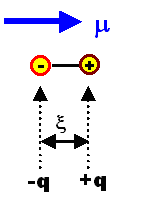
- The center of the positive and negative charges q (= z · e) are now separated by a distance ξ, and we thus induced a dipole moment μ which is defined by
\[\underline{\mu}=q\cdot\underline{\xi}\]

- It is important to understand that μ is a vector because ξ is a vector. The way we define it, its tip will always point towards the positive charge. For schematic drawings we simply draw a little arrow for μ.
The magnitude of this induced dipole moment is a property of our particular atom, or, if we generalize somewhat, of the "particles" or building blocks of the material we are studying.
- In order to describe the bulk material - the sum of the particles - we sum up all individual dipole moments contained in the given volume of the material and divide this sum by the volume V. This gives us the (volume independent) polarization P of the material. Notice that we have a vector sum!
\[\underline{P}=\frac{\Sigma\underline{\mu}}{V}=<\underline{\mu}>\cdot N_\text{V}\]
- With <μ> = average vector dipole moment; NV = density of dipoles (per m3).
- P thus points from the negative to the positive charge, too - a convention opposite to that used for the electrical field.
- The physical dimension of the polarization thus is C/m2; (Coulomb per square meter). i.e. the polarization has the dimension of an area charge, and since μ is a vector, P is a vector, too.
It is important to realize that a polarization P = 0 does not mean that the material does not contain dipole moments, but only that the vector sum of all dipole moments is zero.
- This will always be the case if the dipole moment vectors are randomly distributed with respect to their directions. Look at the picture in one of the next subchapters if you have problems visualizing this. But it will also happen if there is an ordered distribution with pairs of opposing dipole moments; again contemplate a picture in one of the following subchapters if that statment is not directly obvious.
That P has the dimension of C/cm2, i.e. that of an area charge, is not accidental but has an immediate interpretation.
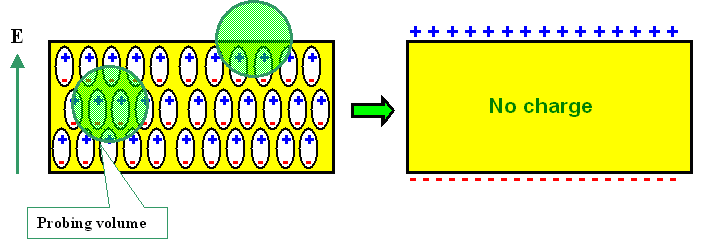
- To see this, let us consider a simple plate capacitor or condenser with a homogeneously polarized material inside its plates. More generally, this describes an isotropic dielectric slab of material in a homogeneous electrical field. We have the following idealized situation:

- For sake of simplicity, all dipole moments have the same direction, but the subsequent reasoning will not change if there is only an average component of P in field direction. If we want to know the charge density ρ inside a small probing volume, it is clearly zero in the volume of the material (if averaged over probing volumes slightly larger than the atomic size), because there are just as many positive as negative charges.
- We are thus left with the surfaces, where there is indeed some charge as indicated in the schematic drawing. At one surface, the charges have effectively moved out a distance ξ , at the other surface they moved in by the same amount. We thus have a surface charge, called a surface polarization charge, that we can calculate.
- The number Nc of charges appearing at a surface with area A is equal to the number of dipoles contained in the surface "volume" VS = A · ξ times the relevant charge q of the dipole. Using ξ to define the volume makes sure that we only have onelayer of dipoles in the volume considered.
- Since we assume a homogeneous dipole distribution, we have the same polarization in any volume and thus P = Σμ / V = ΣμS / VS obtains. Therefore we can write
\[\underline{P}=\frac{\Sigma_\text{V}\;\underline{\mu}}{V}= \frac{\Sigma_\text{S}\;\underline{\mu}}{V_\text{S}}= \frac{\xi\cdot\Sigma_\text{S}\;q}{V_\text{S}}= \frac{\xi\cdot\Sigma_\text{S}\;q}{\xi\cdot A}= \frac{\Sigma_\text{S}\;q}{A}\\ \Sigma_\text{S}\;q=N_\text{c}=P\cdot A\]
- ΣV or ΣS denotes that the summation covers the total volume or the "surface" volume. Somewhere we "lost" the vector property of P, but that only happens because we automatically recognize ξ as being perpendicular to the surface in question.
- While this is a certain degree of sloppiness, it makes life much easier and we will start to drop the underlining of the vectors from now on whenever it is sufficiently clear what is meant.
- The area density σpol of the charge on the surface is then
\[\sigma_\text{pol}=\frac{N_\text{c}}{A}=\frac{P\cdot A}{A}=|\underline{P}|\]
- Of course, σpol is a scalar, which we obtain if we consider P · A to be the scalar product of the vector P and the vector A; the latter being perpendicular to the surface A with magnitude |A| = A.
In purely electrical terms we thus can always replace a material with a homogeneous polarization P by two surfaces perpendicular to some direction, - lets say z - with a surface charge density of Pz (with, of course, different signs on the two different surfaces).
- If the polarization vector is not perpendicular to the surface we chose, we must take the component of the polarization vector parallel to the normal vector of the surface considered . This is automatically taken care of if we use the vector formulation for A.
A dielectric material now quite generally reacts to the presence of an electrical field by becoming polarized and this is expressed by the direction and magnitude of P.
- P is a measurable quantity tied to the specific material under investigation. We now need a material law that connects cause and effect, i.e. a relation between the the electrical field causing the polarization and the amount of polarization produced.
- Finding this law is of course the task of basic theory. But long before the proper theory was found, experiments supplied a simple and rather (but not quite) empirical "law":
If we measure the polarization of a material, we usually find a linear relationship between the applied field E and P, i.e.
\[\underline{P}=\varepsilon_0\cdot\chi\cdot{\color{purple}\underline{E}}\]
- With the proportionality constant chosen to contain ε0, the permittivity constant (of vacuum), times a material parameter χ ("kee"), the dielectric susceptibility.
- Note that including ε0 in the relation is a convention which is useful in the SI system, where charges are always coupled to electrical fields via ε0. There are other systems, however, (usually variants of the cgs system), which are still used by many and provide an unending source of confusion and error.
- This equation is to dielectric material what Ohms law is to conductors. It is no more a real "law of nature" than Ohms law, but a description of many experimental observations for which we will find deeper reasons forthwith.
Our task thus is to calculate χ from basic material parameters.
Connection between the Polarization P and the Electrical Displacement D
Next we need the connection between the polarization P, or the dielectric susceptibility χ, with some older quantities often used in connection with Maxwells equations.
- Historically, inside materials, the electrical field strength E was (and still is) replaced by a vector D called the electrical displacement or electrical flux density, which is defined as
\[\underline{D}=\varepsilon_\Gamma\cdot\varepsilon_0\cdot{\color{purple}\underline{E}}\]
- and εr was (and still is) called the (relative) dielectric constant (DK) of the material (the product εr· ε0 is called the permittivity).
- Note that in the English literature often the abbreviation κ ("Kappa") is used; in proper microelectronics slang one than talks of "low k materials" (pronounced "low khe" as in (O)K) when one actually means "low kappa" or "low epsilon relative".
- D is supposed to give the "acting" flux inside the material.
While this was a smart thing to do for Maxwell and his contemporaries, who couldn't know anything about materials (atoms had not been "invented" then); it is a bit unfortunate in retrospect because the basic quantity is the polarization, based on the elementary dipoles in the material, and the material parameter χ describing this - and not some changed "electrical flux density" and the relative dielectric constant of the material.
- It is, however, easy (if slightly confusing) to make the necessary connections. This is most easily done by looking at a simple plate capacitor. A full treatise is found in a basic module, here we just give the results.
The electric displacement D in a dielectric caused by some external field Eex is the displacement D0 in vacuum plus the polarization P of the material, i.e.
\[\underline{D}=\underline{D}_0+\underline{P}= \varepsilon_0\cdot{\color{purple}\underline{E}}+\underline{P}\]
Inserting everything we see that the relative dielectric constant εr is simply the dielectric susceptibility χ plus 1.
\[\varepsilon_\Gamma=1+\chi\]
For this "translations" we have used the relation P = ε0 · χ · E, which is not an a priori law of nature, but an empirical relation. However, we are going to prove this relation for specific, but very general cases forthwith and thus justify the equations above.
- We have also simply implied that P is parallel to E, which is only reasonable for isotropic materials.
- In anisotropic media, e.g. non-cubic crystals, P does not have to be parallel to E, the scalar quantities εr and χ then are tensors. As before in the case of the electrical conductivity, the polarization and the dielectric displacement then are no longer parallel to the electrical field
- Note right now that this is not an exotic curiosty but a major fact of life for Material Scientists and Engineers. Major industries growing rapidly at present, are based on the anisotropy of the dielctric behavior. Use the link for a first glimpse of what it is all about.
The basic task in the materials science of dielectrics is now to calculate (the tensor) χ from "first principles", i.e. from basic structural knowledge of the material considered. This we will do in the following paragraphs.

