Engineering LibreTexts

4.8: Exercises

  • Page ID
    94074
  • \( \newcommand{\vecs}[1]{\overset { \scriptstyle \rightharpoonup} {\mathbf{#1}} } \)

    \( \newcommand{\vecd}[1]{\overset{-\!-\!\rightharpoonup}{\vphantom{a}\smash {#1}}} \)

    \( \newcommand{\id}{\mathrm{id}}\) \( \newcommand{\Span}{\mathrm{span}}\)

    ( \newcommand{\kernel}{\mathrm{null}\,}\) \( \newcommand{\range}{\mathrm{range}\,}\)

    \( \newcommand{\RealPart}{\mathrm{Re}}\) \( \newcommand{\ImaginaryPart}{\mathrm{Im}}\)

    \( \newcommand{\Argument}{\mathrm{Arg}}\) \( \newcommand{\norm}[1]{\| #1 \|}\)

    \( \newcommand{\inner}[2]{\langle #1, #2 \rangle}\)

    \( \newcommand{\Span}{\mathrm{span}}\)

    \( \newcommand{\id}{\mathrm{id}}\)

    \( \newcommand{\Span}{\mathrm{span}}\)

    \( \newcommand{\kernel}{\mathrm{null}\,}\)

    \( \newcommand{\range}{\mathrm{range}\,}\)

    \( \newcommand{\RealPart}{\mathrm{Re}}\)

    \( \newcommand{\ImaginaryPart}{\mathrm{Im}}\)

    \( \newcommand{\Argument}{\mathrm{Arg}}\)

    \( \newcommand{\norm}[1]{\| #1 \|}\)

    \( \newcommand{\inner}[2]{\langle #1, #2 \rangle}\)

    \( \newcommand{\Span}{\mathrm{span}}\) \( \newcommand{\AA}{\unicode[.8,0]{x212B}}\)

    \( \newcommand{\vectorA}[1]{\vec{#1}}      % arrow\)

    \( \newcommand{\vectorAt}[1]{\vec{\text{#1}}}      % arrow\)

    \( \newcommand{\vectorB}[1]{\overset { \scriptstyle \rightharpoonup} {\mathbf{#1}} } \)

    \( \newcommand{\vectorC}[1]{\textbf{#1}} \)

    \( \newcommand{\vectorD}[1]{\overrightarrow{#1}} \)

    \( \newcommand{\vectorDt}[1]{\overrightarrow{\text{#1}}} \)

    \( \newcommand{\vectE}[1]{\overset{-\!-\!\rightharpoonup}{\vphantom{a}\smash{\mathbf {#1}}}} \)

    \( \newcommand{\vecs}[1]{\overset { \scriptstyle \rightharpoonup} {\mathbf{#1}} } \)

    \( \newcommand{\vecd}[1]{\overset{-\!-\!\rightharpoonup}{\vphantom{a}\smash {#1}}} \)

    \(\newcommand{\avec}{\mathbf a}\) \(\newcommand{\bvec}{\mathbf b}\) \(\newcommand{\cvec}{\mathbf c}\) \(\newcommand{\dvec}{\mathbf d}\) \(\newcommand{\dtil}{\widetilde{\mathbf d}}\) \(\newcommand{\evec}{\mathbf e}\) \(\newcommand{\fvec}{\mathbf f}\) \(\newcommand{\nvec}{\mathbf n}\) \(\newcommand{\pvec}{\mathbf p}\) \(\newcommand{\qvec}{\mathbf q}\) \(\newcommand{\svec}{\mathbf s}\) \(\newcommand{\tvec}{\mathbf t}\) \(\newcommand{\uvec}{\mathbf u}\) \(\newcommand{\vvec}{\mathbf v}\) \(\newcommand{\wvec}{\mathbf w}\) \(\newcommand{\xvec}{\mathbf x}\) \(\newcommand{\yvec}{\mathbf y}\) \(\newcommand{\zvec}{\mathbf z}\) \(\newcommand{\rvec}{\mathbf r}\) \(\newcommand{\mvec}{\mathbf m}\) \(\newcommand{\zerovec}{\mathbf 0}\) \(\newcommand{\onevec}{\mathbf 1}\) \(\newcommand{\real}{\mathbb R}\) \(\newcommand{\twovec}[2]{\left[\begin{array}{r}#1 \\ #2 \end{array}\right]}\) \(\newcommand{\ctwovec}[2]{\left[\begin{array}{c}#1 \\ #2 \end{array}\right]}\) \(\newcommand{\threevec}[3]{\left[\begin{array}{r}#1 \\ #2 \\ #3 \end{array}\right]}\) \(\newcommand{\cthreevec}[3]{\left[\begin{array}{c}#1 \\ #2 \\ #3 \end{array}\right]}\) \(\newcommand{\fourvec}[4]{\left[\begin{array}{r}#1 \\ #2 \\ #3 \\ #4 \end{array}\right]}\) \(\newcommand{\cfourvec}[4]{\left[\begin{array}{c}#1 \\ #2 \\ #3 \\ #4 \end{array}\right]}\) \(\newcommand{\fivevec}[5]{\left[\begin{array}{r}#1 \\ #2 \\ #3 \\ #4 \\ #5 \\ \end{array}\right]}\) \(\newcommand{\cfivevec}[5]{\left[\begin{array}{c}#1 \\ #2 \\ #3 \\ #4 \\ #5 \\ \end{array}\right]}\) \(\newcommand{\mattwo}[4]{\left[\begin{array}{rr}#1 \amp #2 \\ #3 \amp #4 \\ \end{array}\right]}\) \(\newcommand{\laspan}[1]{\text{Span}\{#1\}}\) \(\newcommand{\bcal}{\cal B}\) \(\newcommand{\ccal}{\cal C}\) \(\newcommand{\scal}{\cal S}\) \(\newcommand{\wcal}{\cal W}\) \(\newcommand{\ecal}{\cal E}\) \(\newcommand{\coords}[2]{\left\{#1\right\}_{#2}}\) \(\newcommand{\gray}[1]{\color{gray}{#1}}\) \(\newcommand{\lgray}[1]{\color{lightgray}{#1}}\) \(\newcommand{\rank}{\operatorname{rank}}\) \(\newcommand{\row}{\text{Row}}\) \(\newcommand{\col}{\text{Col}}\) \(\renewcommand{\row}{\text{Row}}\) \(\newcommand{\nul}{\text{Nul}}\) \(\newcommand{\var}{\text{Var}}\) \(\newcommand{\corr}{\text{corr}}\) \(\newcommand{\len}[1]{\left|#1\right|}\) \(\newcommand{\bbar}{\overline{\bvec}}\) \(\newcommand{\bhat}{\widehat{\bvec}}\) \(\newcommand{\bperp}{\bvec^\perp}\) \(\newcommand{\xhat}{\widehat{\xvec}}\) \(\newcommand{\vhat}{\widehat{\vvec}}\) \(\newcommand{\uhat}{\widehat{\uvec}}\) \(\newcommand{\what}{\widehat{\wvec}}\) \(\newcommand{\Sighat}{\widehat{\Sigma}}\) \(\newcommand{\lt}{<}\) \(\newcommand{\gt}{>}\) \(\newcommand{\amp}{&}\) \(\definecolor{fillinmathshade}{gray}{0.9}\)

    8.8.1: Analysis Problems

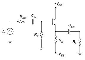
    1. Draw the AC load line for the circuit of Figure \(\PageIndex{1}\). Also determine the compliance, maximum load power, maximum transistor dissipation and efficiency. \(V_{CC}\) = 6 V, \(V_{EE}\) = −12 V, \(R_{gen}\) = 50 \(\Omega\), \(R_B\) = 2.2 k\(\Omega\), \(R_E\) = 470 \(\Omega\), \(R_L\) = 75 \(\Omega\).

    clipboard_e6d2774a3f8006729bf18c64d568cec65.png

    Figure \(\PageIndex{1}\)

    2. Recalculate Problem 1 if the load is halved.

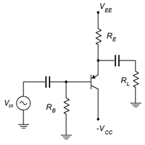
    3. Determine if the circuit of Figure \(\PageIndex{2}\) has a centered Q point on its AC load line. \(V_{CC}\) = −10 V, \(V_{EE}\) = 15 V, \(R_B\) = 1 k\(\Omega\), \(R_E\) = 330 \(\Omega\), \(R_L\) = 50 \(\Omega\).

    clipboard_e5e774364d7ed20e2ade15c3eb91c6d72.png

    Figure \(\PageIndex{2}\)

    4. Draw the AC load line for the circuit of Figure \(\PageIndex{2}\). Also determine the compliance, maximum load power, maximum transistor dissipation and efficiency. \(V_{CC}\) = −8 V, \(V_{EE}\) = 12 V, \(R_B\) = 1 k\(\Omega\), \(R_E\) = 330 \(\Omega\), \(R_L\) = 32 \(\Omega\).

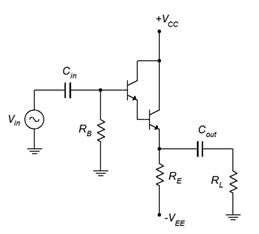
    5. Draw the AC load line for the circuit of Figure \(\PageIndex{3}\). Also determine the compliance, maximum load power, maximum transistor dissipation and efficiency. \(V_{CC}\) = 15 V, \(V_{EE}\) = −20 V, \(R_B\) = 10 k\(\Omega\), \(R_E\) = 100 \(\Omega\), \(R_L\) = 16 \(\Omega\).

    clipboard_e2f3681c11a9d89f8956c69796e7368cb.png

    Figure \(\PageIndex{3}\)

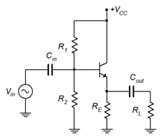
    6. Determine if the circuit of Figure \(\PageIndex{4}\) has a centered Q point on its AC load line. \(V_{CC}\) = 30 V, \(R_1\) = 3.9 k\(\Omega\), \(R_2\) = 3.3 k\(\Omega\), \(R_E\) = 560 \(\Omega\), \(R_L\) = 50 \(\Omega\).

    clipboard_efda8b7039044074cd3543eeddea5303e.png

    Figure \(\PageIndex{4}\)

    7. Draw the AC load line for the circuit of Figure \(\PageIndex{4}\). Also determine the compliance, maximum load power, maximum transistor dissipation and efficiency. \(V_{CC}\) = 30 V, \(R_1\) = 2.2 k\(\Omega\), \(R_2\)= 2.2 k\(\Omega\), \(R_E\) = 470 \(\Omega\), \(R_L\) = 32 \(\Omega\).

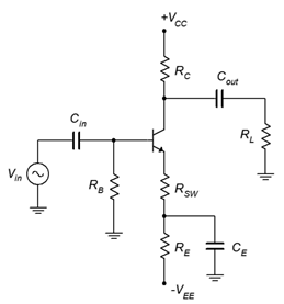
    8. Determine if the circuit of Figure \(\PageIndex{5}\) has a centered Q point on its AC load line. \(V_{CC}\) = 15 V, \(V_{EE}\) = −15 V, \(R_B\) = 1 k\(\Omega\), \(R_E\) = 510 \(\Omega\), \(R_{SW}\) = 10 \(\Omega\), \(R_C\) = 270 \(\Omega\), \(R_L\) = 50 \(\Omega\).

    clipboard_e71da0a3110213fd347a638d2d4cb9c44.png

    Figure \(\PageIndex{5}\)

    9. Draw the AC load line for the circuit of Figure \(\PageIndex{5}\). Also determine the compliance, maximum load power, maximum transistor dissipation and efficiency. \(V_{CC}\) = 25 V, \(V_{EE}\) = −15 V, \(R_B\) = 1 k\(\Omega\), \(R_E\) = 270 \(\Omega\), \(R_{SW}\) = 6.8 \(\Omega\), \(R_C\) = 330 \(\Omega\), \(R_L\) = 16 \(\Omega\).

    10. A power transistor has a \(P_{D(max)}\) of 50 watts at 25\(^{\circ}\)C. It has a derating factor of 0.4 W/C\(^{\circ}\). Will this transistor be sufficient for a circuit that needs to dissipate 40 watts at 85\(^{\circ}\)C?

    11. A power transistor has a \(P_{D(max)}\) of 100 watts at 25\(^{\circ}\)C. It has a derating factor of 0.6 W/C\(^{\circ}\). Will this transistor be sufficient for a circuit that needs to dissipate 65 watts at 75\(^{\circ}\)C?

    12. Determine the appropriate heat sink rating for a power device rated as follows: \(T_{j(max)}\) = 175\(^{\circ}\)C, TO-3 case style, \(\theta_{jc}\) = 1.5 C\(^{\circ}\)/W. The device will be dissipating a maximum of 25 W in an ambient temperature of 35\(^{\circ}\)C. Assume that the heat sink will be mounted with heat sink grease and a 0.003 mica insulator.

    13. Determine the appropriate heat sink rating for a power device rated as follows: \(T_{j(max)}\) = 165\(^{\circ}\)C, TO-220 case style, \(\theta_{jc}\) = 3 C\(^{\circ}\)/W. The device will be dissipating a maximum of 15 W in an ambient temperature of 35\(^{\circ}\)C. Assume that the heat sink will be mounted with heat sink grease and a 0.002 mica insulator.

    8.8.2: Design Problems

    14. Alter the emitter power supply in the circuit described in Problem 1 to achieve a centered Q point.

    15. Alter the emitter power supply in the circuit described in Problem 4 to achieve a centered Q point.

    8.8.3: Challenge Problems

    16. Find a heat sink (make and model number) that will meet the thermal resistance requirement for Problem 12 with no more than 400 feet/minute of forced air.

    17. Alter the voltage divider in the circuit described in Problem 6 to achieve a centered Q point.

    8.8.3: Computer Simulation Problems

    18. Perform a transient analysis for the circuit described in Problem 1 to verify the compliance.

    19. Perform a transient analysis for the circuit described in Problem 4 to verify the compliance.

    20. Perform a transient analysis for the circuit described in Problem 9 to verify the compliance.


    This page titled 4.8: Exercises is shared under a CC BY-NC-SA 4.0 license and was authored, remixed, and/or curated by James M. Fiore via source content that was edited to the style and standards of the LibreTexts platform.