
4.8: Exercises
- Page ID
- 98425

\( \newcommand{\vecs}[1]{\overset { \scriptstyle \rightharpoonup} {\mathbf{#1}} } \)
\( \newcommand{\vecd}[1]{\overset{-\!-\!\rightharpoonup}{\vphantom{a}\smash {#1}}} \)
\( \newcommand{\dsum}{\displaystyle\sum\limits} \)
\( \newcommand{\dint}{\displaystyle\int\limits} \)
\( \newcommand{\dlim}{\displaystyle\lim\limits} \)
\( \newcommand{\id}{\mathrm{id}}\) \( \newcommand{\Span}{\mathrm{span}}\)
( \newcommand{\kernel}{\mathrm{null}\,}\) \( \newcommand{\range}{\mathrm{range}\,}\)
\( \newcommand{\RealPart}{\mathrm{Re}}\) \( \newcommand{\ImaginaryPart}{\mathrm{Im}}\)
\( \newcommand{\Argument}{\mathrm{Arg}}\) \( \newcommand{\norm}[1]{\| #1 \|}\)
\( \newcommand{\inner}[2]{\langle #1, #2 \rangle}\)
\( \newcommand{\Span}{\mathrm{span}}\)
\( \newcommand{\id}{\mathrm{id}}\)
\( \newcommand{\Span}{\mathrm{span}}\)
\( \newcommand{\kernel}{\mathrm{null}\,}\)
\( \newcommand{\range}{\mathrm{range}\,}\)
\( \newcommand{\RealPart}{\mathrm{Re}}\)
\( \newcommand{\ImaginaryPart}{\mathrm{Im}}\)
\( \newcommand{\Argument}{\mathrm{Arg}}\)
\( \newcommand{\norm}[1]{\| #1 \|}\)
\( \newcommand{\inner}[2]{\langle #1, #2 \rangle}\)
\( \newcommand{\Span}{\mathrm{span}}\) \( \newcommand{\AA}{\unicode[.8,0]{x212B}}\)
\( \newcommand{\vectorA}[1]{\vec{#1}} % arrow\)
\( \newcommand{\vectorAt}[1]{\vec{\text{#1}}} % arrow\)
\( \newcommand{\vectorB}[1]{\overset { \scriptstyle \rightharpoonup} {\mathbf{#1}} } \)
\( \newcommand{\vectorC}[1]{\textbf{#1}} \)
\( \newcommand{\vectorD}[1]{\overrightarrow{#1}} \)
\( \newcommand{\vectorDt}[1]{\overrightarrow{\text{#1}}} \)
\( \newcommand{\vectE}[1]{\overset{-\!-\!\rightharpoonup}{\vphantom{a}\smash{\mathbf {#1}}}} \)
\( \newcommand{\vecs}[1]{\overset { \scriptstyle \rightharpoonup} {\mathbf{#1}} } \)
\(\newcommand{\longvect}{\overrightarrow}\)
\( \newcommand{\vecd}[1]{\overset{-\!-\!\rightharpoonup}{\vphantom{a}\smash {#1}}} \)
\(\newcommand{\avec}{\mathbf a}\) \(\newcommand{\bvec}{\mathbf b}\) \(\newcommand{\cvec}{\mathbf c}\) \(\newcommand{\dvec}{\mathbf d}\) \(\newcommand{\dtil}{\widetilde{\mathbf d}}\) \(\newcommand{\evec}{\mathbf e}\) \(\newcommand{\fvec}{\mathbf f}\) \(\newcommand{\nvec}{\mathbf n}\) \(\newcommand{\pvec}{\mathbf p}\) \(\newcommand{\qvec}{\mathbf q}\) \(\newcommand{\svec}{\mathbf s}\) \(\newcommand{\tvec}{\mathbf t}\) \(\newcommand{\uvec}{\mathbf u}\) \(\newcommand{\vvec}{\mathbf v}\) \(\newcommand{\wvec}{\mathbf w}\) \(\newcommand{\xvec}{\mathbf x}\) \(\newcommand{\yvec}{\mathbf y}\) \(\newcommand{\zvec}{\mathbf z}\) \(\newcommand{\rvec}{\mathbf r}\) \(\newcommand{\mvec}{\mathbf m}\) \(\newcommand{\zerovec}{\mathbf 0}\) \(\newcommand{\onevec}{\mathbf 1}\) \(\newcommand{\real}{\mathbb R}\) \(\newcommand{\twovec}[2]{\left[\begin{array}{r}#1 \\ #2 \end{array}\right]}\) \(\newcommand{\ctwovec}[2]{\left[\begin{array}{c}#1 \\ #2 \end{array}\right]}\) \(\newcommand{\threevec}[3]{\left[\begin{array}{r}#1 \\ #2 \\ #3 \end{array}\right]}\) \(\newcommand{\cthreevec}[3]{\left[\begin{array}{c}#1 \\ #2 \\ #3 \end{array}\right]}\) \(\newcommand{\fourvec}[4]{\left[\begin{array}{r}#1 \\ #2 \\ #3 \\ #4 \end{array}\right]}\) \(\newcommand{\cfourvec}[4]{\left[\begin{array}{c}#1 \\ #2 \\ #3 \\ #4 \end{array}\right]}\) \(\newcommand{\fivevec}[5]{\left[\begin{array}{r}#1 \\ #2 \\ #3 \\ #4 \\ #5 \\ \end{array}\right]}\) \(\newcommand{\cfivevec}[5]{\left[\begin{array}{c}#1 \\ #2 \\ #3 \\ #4 \\ #5 \\ \end{array}\right]}\) \(\newcommand{\mattwo}[4]{\left[\begin{array}{rr}#1 \amp #2 \\ #3 \amp #4 \\ \end{array}\right]}\) \(\newcommand{\laspan}[1]{\text{Span}\{#1\}}\) \(\newcommand{\bcal}{\cal B}\) \(\newcommand{\ccal}{\cal C}\) \(\newcommand{\scal}{\cal S}\) \(\newcommand{\wcal}{\cal W}\) \(\newcommand{\ecal}{\cal E}\) \(\newcommand{\coords}[2]{\left\{#1\right\}_{#2}}\) \(\newcommand{\gray}[1]{\color{gray}{#1}}\) \(\newcommand{\lgray}[1]{\color{lightgray}{#1}}\) \(\newcommand{\rank}{\operatorname{rank}}\) \(\newcommand{\row}{\text{Row}}\) \(\newcommand{\col}{\text{Col}}\) \(\renewcommand{\row}{\text{Row}}\) \(\newcommand{\nul}{\text{Nul}}\) \(\newcommand{\var}{\text{Var}}\) \(\newcommand{\corr}{\text{corr}}\) \(\newcommand{\len}[1]{\left|#1\right|}\) \(\newcommand{\bbar}{\overline{\bvec}}\) \(\newcommand{\bhat}{\widehat{\bvec}}\) \(\newcommand{\bperp}{\bvec^\perp}\) \(\newcommand{\xhat}{\widehat{\xvec}}\) \(\newcommand{\vhat}{\widehat{\vvec}}\) \(\newcommand{\uhat}{\widehat{\uvec}}\) \(\newcommand{\what}{\widehat{\wvec}}\) \(\newcommand{\Sighat}{\widehat{\Sigma}}\) \(\newcommand{\lt}{<}\) \(\newcommand{\gt}{>}\) \(\newcommand{\amp}{&}\) \(\definecolor{fillinmathshade}{gray}{0.9}\)Analysis
1. For the circuit shown in Figure 6.9.1 , determine the equivalent current source.
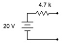
Figure 6.9.1
Answer 1
- 4.26mA source in parallel with 4.7k resistor
2. Given the circuit shown in Figure 6.9.2 , determine the equivalent current source.
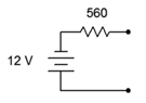
Figure 6.9.2
3. Determine the equivalent current source for the circuit shown in Figure 6.9.3 .
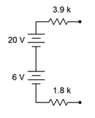
Figure 6.9.3
Answer 3
- 4.56mA source in parallel with 5.7k resistor
4. For the circuit shown in Figure 6.9.4 , determine the equivalent current source.
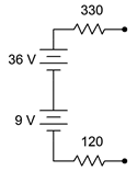
Figure 6.9.4
5. For the circuit shown in Figure 6.9.5 , determine the equivalent voltage source.
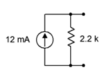
Figure 6.9.5
Answer 5
- 26.4V in series with 2.2k resistor
6. Given the circuit shown in Figure 6.9.6 , determine the equivalent voltage source.
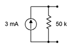
Figure 6.9.6
7. Determine the equivalent voltage source for the circuit shown in Figure 6.9.7 . 800\(\ohm\)
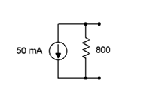
Figure 6.9.7
Answer 7
- -40V in series with 800 \(\Omega\) resistor
8. For the circuit shown in Figure 6.9.8 , determine the equivalent voltage source.
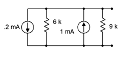
Figure 6.9.8
9. Given the circuit shown in Figure 6.9.9 , determine the equivalent voltage source.
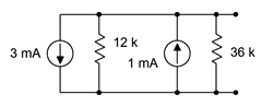
Figure 6.9.9
Answer 9
- -18V in series with 9k\(\Omega\) resistor
10. Using source conversion, find \(V_b\) for the circuit shown in Figure 6.9.10 .
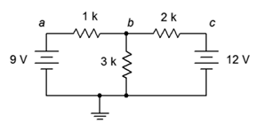
Figure 6.9.10
11. Using source conversion, find the current through the 3 k\(\Omega\) resistor in the circuit of Figure 6.9.11 .
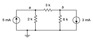
Figure 6.9.11
Answer 11
- 2.55mA left to right
12. Using source conversion, find \(V_b\) for the circuit shown in Figure 6.9.12 .
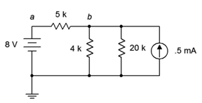
Figure 6.9.12
13. Using source conversion, find \(V_a\) for the circuit shown in Figure 6.9.13 .
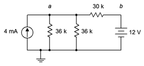
Figure 6.9.13
Answer 13
- 49.5V
14. Using source conversion, find \(V_b\) for the circuit shown in Figure 6.9.14 .
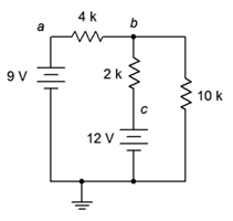
Figure 6.9.14
15. Using superposition, determine \(V_b\) for the circuit shown in Figure 6.9.10 .
Answer 15
- 8.18V
16. Using superposition, find the current through the 3 k\(\Omega\) resistor for the circuit of Figure 6.9.10 .
17. Using superposition, find the current through the 3 k\(\Omega\) resistor for the circuit of Figure 6.9.11 .
Answer 17
- 2.55mA
18. Using superposition, determine \(V_{ab}\) for the circuit shown in Figure 6.9.11 .
19. Using superposition, determine \(V_b\) for the circuit shown in Figure 6.9.12 .
Answer 19
- 4.2V
20. Using superposition, find the current through the 4 k\(\Omega\) resistor for the circuit of Figure 6.9.12 .
21. Using superposition, find the current through the 30 k\(\Omega\) resistor for the circuit of Figure 6.9.13 .
Answer 21
- 1.25mA
22. Using superposition, determine \(V_a\) for the circuit shown in Figure 6.9.13 .
23. Using superposition, determine \(V_{ba}\) for the circuit shown in Figure 6.9.14 .
Answer 23
- 0.7V
24. Using superposition, find the current through the 10 k\(\Omega\) resistor for the circuit of Figure 6.9.14 .
25. Using superposition, find the current through the 1.5 k\(\Omega\) resistor for the circuit of Figure 6.9.15 .
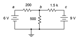
Figure 6.9.15
Answer 25
- 8.09mA
26. Using superposition, determine \(V_{ab}\) for the circuit shown in Figure 6.9.15 .
27. Using superposition, determine \(V_b\) for the circuit shown in Figure 6.9.16 .
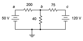
Figure 6.9.16
Answer 27
- 42.7V
28. Using superposition, find the current through the 200 \(\Omega\) resistor for the circuit of Figure 6.9.16 .
29. Using superposition, find the current through the 4 k\(\Omega\) resistor for the circuit of Figure 6.9.17 .
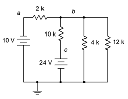
Figure 6.9.17
Answer 29
- 0.696mA
30. Using superposition, determine \(V_b\) for the circuit shown in Figure 6.9.17 .
31. Is it possible to determine \(V_b\) in Figure 6.9.17 by using source conversions instead of superposition? Why/why not?
Answer 31
- Yes, it's only current sources and resistors in parallel
32. Using superposition, determine \(V_{bc}\) for the circuit shown in Figure 6.9.18 .
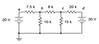
Figure 6.9.18
33. Using superposition, find the current through the 10 k\(\Omega\) resistor for the circuit of Figure 6.9.18 .
Answer 33
- 1.17mA
34. Using superposition, find the currents through the 100 \(\Omega\) and 700 \(\Omega\) resistors for the circuit shown in Figure 6.9.19 .
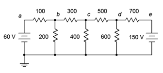
Figure 6.9.19
35. Using superposition, determine \(V_{bd}\) for the circuit shown in Figure 6.9.19 .
Answer 35
- -15.65V
36. Is it possible to determine \(V_{bd}\) in Figure 6.9.19 by using source conversions instead of superposition? Why/why not?
37. Using superposition, determine \(V_{ad}\) for the circuit shown in Figure 6.9.20 .
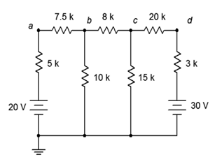
Figure 6.9.20
Answer 37
- -11.6V
38. Using superposition, find the current through the 20 k\(\Omega\) resistor for the circuit shown in Figure 6.9.20 .
39. Using superposition, find the current through the 12 k\(\Omega\) resistor for the circuit shown in Figure 6.9.21 .
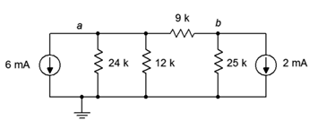
Figure 6.9.21
Answer 39
- 4.03mA (up)
40. Using superposition, determine \(V_b\) for the circuit shown in Figure 6.9.21 .
41. Using superposition, determine \(V_b\) for the circuit shown in Figure 6.9.22 .
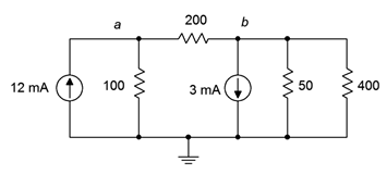
Figure 6.9.22
Answer 41
- 38.7mV
42. Using superposition, find the current through the 100 \(\Omega\) resistor for the circuit of Figure 6.9.22 .
43. Using superposition, find the current through the 5 k\(\Omega\) resistor for the circuit of Figure 6.9.23 .
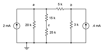
Figure 6.9.23
Answer 43
- 1.19mA left to right
44. Using superposition, determine \(V_c\) for the circuit shown in Figure 6.9.23 .
45. Given the circuit shown in Figure 6.9.24 , determine the Thévenin equivalent circuit that is driving the 4 k\(\Omega\) resistor.
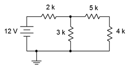
Figure 6.9.24
Answer 45
- 7.2V with 6.2k\(\Omega\)
46. Given the circuit shown in Figure 6.9.24 , determine the Norton equivalent circuit driving the 4 k\(\Omega\) resistor.
47. Given the circuit shown in Figure 6.9.24 , determine the Norton equivalent circuit driving the 12 k\(\Omega\) resistor.
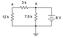
Figure 6.9.25
Answer 47
- 2mA with 3k\(\Omega\) resistor
48. Determine the Thévenin equivalent circuit driving the 12 k\(\Omega\) resistor for the circuit shown in Figure 6.9.25 .
49. Given the circuit shown in Figure 6.9.26 , determine the Thévenin equivalent circuit that is driving the 20 k\(\Omega\) resistor.
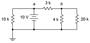
Figure 6.9.26
Answer 49
- 5.71V with 1.71\(k\Omega\) resistor
50. For the circuit shown in Figure 6.9.26 , determine the Norton equivalent circuit driving the 4 k\(\Omega\) resistor.
51. Given the circuit shown in Figure 6.9.27 , determine the Norton equivalent circuit driving the 40 \(\Omega\) resistor.
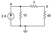
Figure 6.9.27
Answer 51
- 1.538A with 13 \(\Omega\) resistor
52. Determine the Thévenin equivalent circuit driving the 10 \(\Omega\) resistor for the circuit shown in Figure 6.9.27 .
53. Given the circuit shown in Figure 6.9.28 , determine the Norton equivalent circuit driving the 12 k\(\Omega\) resistor.
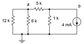
Figure 6.9.28
Answer 53
- 66.7 \(\mu A\) with 3 \(k\Omega\) resistor
54. Given the circuit of Figure 6.9.24 , determine the power in the 4 k\(\Omega\) resistor. If this resistor can be replaced with any other value, is it possible to achieve a higher power? Why/why not?
55. Given the circuit of Figure 6.9.25 , determine the power in the 12 k\(\Omega\) resistor. If this resistor can be replaced with any other value, is it possible to achieve a higher power? Why/why not?
Answer 55
- 1.92mW. Yes, match \(R_{Th}\)
56. Given the circuit of Figure 6.9.27 , determine the power in the 40 \(\Omega\) resistor. If this resistor can be replaced with any other value, is it possible to achieve a higher power? Why/why not?
57. Given the circuit of Figure 6.9.28 , determine the power in the 6 k\(\Omega\) resistor. If this resistor can be replaced with any other value, is it possible to achieve a higher power? Why/why not?
Answer 57
- 4.27\(\mu W\). Yes, match \(R_{Th}\)
Design
58. Consider the 4 k\(\Omega\) resistor to be the load in Figure 6.9.24 . Determine a new value for the load in order to achieve maximum load power. Also determine the maximum load power.
59. Consider the 12 k\(\Omega\) resistor to be the load in Figure 6.9.25 . Determine a new value for the load in order to achieve maximum load power. Also determine the maximum load power.
Answer 59
- 1.92mW. Yes, match \(R_{Th}\)
60. Consider the 40 \(\Omega\) resistor to be the load in Figure 6.9.27 . Determine a new value for the load in order to achieve maximum load power. Also determine the maximum load power.
61. Consider the 6 k\(\Omega\) resistor to be the load in Figure 6.9.28 . Determine a new value for the load in order to achieve maximum load power. Also determine the maximum load power.
Answer 61
- 4k\(\Omega\), 4.44\(\mu W\)
62. Redesign the circuit of Figure 6.9.15 so that it uses only current sources and produces the same component currents and voltages as the original circuit.
63. Redesign the circuit of Figure 6.9.17 so that it uses only current sources and produces the same component currents and voltages as the original circuit.
Answer 63
- Replace 10V+2k\(\Omega\) with 5mA||2k\(\Omega\) and 24V+10k\(\Omega\) with 2.4mA||10k\(\Omega\)
64. Redesign the circuit of Figure 6.9.21 so that it uses only voltage sources and produces the same component currents and voltages as the original circuit.
65. Redesign the circuit of Figure 6.9.23 so that it uses only voltage sources and produces the same component currents and voltages as the original circuit.
Answer 65
- Replace 2mA||20k\(\Omega\) with 40V + 20k\(\Omega\), and 0.4mA||3k\(\Omega\) with 1.2V + 3k\(\Omega\)
66. Convert the delta network of Figure 6.9.29 into a Y network.
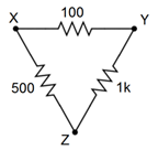
Figure 6.9.29
67. Convert the pi network of Figure 6.9.30 into a T network.
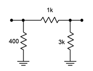
Figure 6.9.30
Answer 67
68. Convert the Y network of Figure 6.9.31 into a delta network.
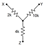
Figure 6.9.31
69. Convert the T network of Figure 6.9.32 into a pi network.
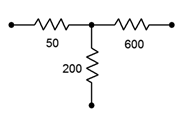
Figure 6.9.32
Answer 69
Challenge
70. Redesign the circuit of Figure 6.9.33 so that it uses only current sources and produces the same node voltages as the original circuit.
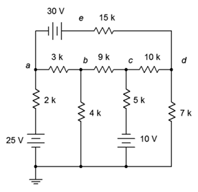
Figure 6.9.33
71. Using any combination of techniques, find the current through the 9 k\(\Omega\) resistor for the circuit of Figure 6.9.33 .
72. Using any combination of techniques, determine \(V_{bc}\) for the circuit shown in Figure 6.9.33 .
73. Is it possible to determine \(V_{bc}\) in Figure 6.9.33 by using just source conversions? Why/why not?
74. Using superposition, find the current through the 25 \(\Omega\) resistor for the circuit of Figure 6.9.34 .

Figure 6.9.34
75. Using superposition, find \(V_{ab}\) in the circuit of Figure 6.9.34 .
76. Redesign the circuit of Figure 6.9.34 using only voltage sources so that it achieves the same node voltages as the original.
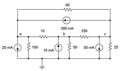
Figure 6.9.35
77. Is it possible to determine \(V_{bc}\) in Figure 6.9.35 by using just source conversions or just superposition? Why/why not?
78. Using any combination of techniques, find the current through the 100 \(\Omega\) resistor for the circuit shown in Figure 6.9.35 .
79. Redesign the circuit of Figure 6.9.35 so that it uses only voltage sources and produces the same node voltages as the original circuit.
80. Determine the Thévenin and Norton equivalents driving the 40 \(\Omega\) resistor for the circuit shown in Figure 6.9.16 .
81. Determine the Thévenin and Norton equivalents driving the 12 k\(\Omega\) resistor for the circuit shown in Figure 6.9.17 .
Answer 81
Thevenin's Equivalent Answer:
82. Given the circuit of Figure 6.9.26 , determine if the 4 k\(\Omega\) resistor is the optimal value to achieve maximum power dissipation in that resistor. If it is not, determine the value that will produce maximum power in the resistor along with the resulting power.
83. For the circuit of Figure 6.9.36 , determine an equivalent circuit using just a single voltage source.
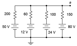
Figure 6.9.36
Simulation
84. Using DC bias simulations, compare the original circuit of problem 1 to its converted equivalent. Do this by connecting a resistor to the output terminals, trying several different resistance values and checking to see if the two circuits always produce the same voltage across this resistor.
85. Using DC bias simulations, compare the original circuit of problem 5 to its converted equivalent. Do this by connecting a resistor to the output terminals, trying several different resistance values and checking to see if the two circuits always produce the same voltage across this resistor.
86. Perform a DC bias simulation on the circuit of problem 11 to verify the node voltages.
87. Perform a DC bias simulation on the circuit of problem 13 to verify the node voltages.
88. Perform a DC bias simulation on the circuit of problem 19 to verify the node voltages.
89. Perform a DC bias simulation on the circuit of problem 21 to verify the resistor current.
90. Create DC bias simulations of the original and equivalent circuits generated in problem 45 to determine if the equivalent circuit is truly equivalent. Do this by substituting several different values for the 4 k\(\Omega\) resistor in both circuits to see if the same load voltage is obtained for both circuits.
91. Create DC bias simulations of the original and equivalent circuits generated in problem 49 to determine if the equivalent circuit is truly equivalent. Do this by substituting several different values for the 20 k\(\Omega\) resistor in both circuits to see if the same load voltage is obtained for both circuits.
92. Create DC bias simulations of the original and equivalent circuits generated in problem 53 to determine if the equivalent circuit is truly equivalent. Do this by substituting several different values for the 12 k\(\Omega\) resistor in both circuits to see if the same load voltage is obtained for both circuits.
93. Perform a DC bias simulation on the circuit of problem 63 to verify that the node voltages of the new design match those of the original.
94. Perform a DC bias simulation on the circuit of problem 65 to verify that the node voltages of the new design match those of the original.
95. Using either Monte Carlo simulation or multiple DC bias simulations, verify that the resistance calculated in problem 55 achieves maximum power. Do this by trying several resistor values near the calculated value, and determining the power for each based on the squared load voltages.
96. Using either Monte Carlo simulation or multiple DC bias simulations, verify that the resistance calculated in problem 56 achieves maximum power. Do this by trying several resistor values near the calculated value, and determining the power for each based on the squared load voltages.
This XKCD comic is too large to fit on this page. Just go to this link instead: