
6.2.3: Compressor
- Page ID
- 78140

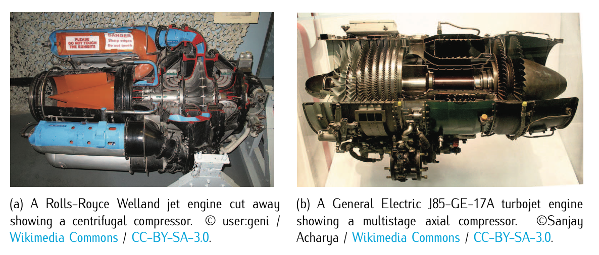
Figure 6.5: Types of jet compressors.
In the compressor, the pressure of the incoming air is increased by mechanical work. There are two fundamental types of compressors: axial and centrifugal. See Figure 6.5 as illustration of these two types.
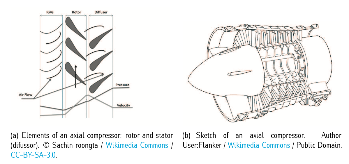
Figure 6.6: Axial compressor.
In axial compressors the flow goes parallel to the rotation axis, i.e., parallel to the axial direction. In a centrifugal compressor the airflow goes perpendicular to the axis of rotation. The very first jet engines used centrifugal compressors, and they are still used on small turbojets. Modern turbojets and turbofans typically employ axial compressors. An axial compressor is composed by a duple rotor-stator (if the compressor is multistage, then there will one duple per stage). In short, the rotor increases the absolute velocity of the fluid and the stator converts this into pressure increase as Figure 6.6 illustrates.
A typical, single-stage, centrifugal compressor increases the airflow pressure by a factor of 4. A similar single stage axial compressor will produce a pressure increase of between 15% and 60%, i.e., pressure ratios of 1.15-1.6 (small when compared to the centrifugal one). The fundamental advantage of axial compressor is that several stages can be easily linked together, giving rise to a multistage axial compressor, which can supply air with a pressure ratio of 40. It is much more difficult to produce an efficient multistage centrifugal compressor and therefore most high-compression jet engines incorporate multistage axial compressors. If only a moderate amount of compression is required, the best choice would be a centrifugal compressor.
Let us now focus on the equations that govern the evolution of the airflow over the compressor.
The pressure increase is quantified in terms of the so-called compressor pressure ratio (CPR), which is the ratio between exiting and entering air pressure. Using the station numbers of Figure 6.2, the CPR can be expressed as the stagnation pressure at stage 3 (\(p_{3t}\)) divided by the stagnation pressure at stage 2 (\(p_{2t}\)):
\[CPR = \dfrac{p_{3t}}{p_{2t}}.\nonumber\]
The process can be considered adiabatic. Thus, according to the thermodynamic relation between pressure and temperature given in Equation (6.2.1.9), CPR can be also expressed as follows:
\[CPR = \dfrac{p_{3t}}{p_{2t}} = \left (\dfrac{T_{3t}}{T_{2t}} \right )^{\tfrac{\gamma}{(\gamma - 1)}},\nonumber\]
where \(\gamma\) is the ratio of specific heats (\(\gamma \approx 1.4\) for air).
Referring the reader to Section 6.2.1 and doing some algebraic operations, the mechanical work consumed by the compressor can be expressed:
\[W_{comp} = \dfrac{cT_{2t}}{\eta_c} (CPR^{\tfrac{(\gamma - 1)}{\gamma}} - 1),\]
where \(c\) is the specific heat of the gas and \(\eta_c\) is the compressor efficiency. The efficiency factor is included to account for the real performance as opposed to the ideal one. Notice that the needed mechanical work is provided by the power turbine, which is connected to the compressor by a central shaft.