
10.8: Exercises
- Page ID
- 78390

\( \newcommand{\vecs}[1]{\overset { \scriptstyle \rightharpoonup} {\mathbf{#1}} } \)
\( \newcommand{\vecd}[1]{\overset{-\!-\!\rightharpoonup}{\vphantom{a}\smash {#1}}} \)
\( \newcommand{\dsum}{\displaystyle\sum\limits} \)
\( \newcommand{\dint}{\displaystyle\int\limits} \)
\( \newcommand{\dlim}{\displaystyle\lim\limits} \)
\( \newcommand{\id}{\mathrm{id}}\) \( \newcommand{\Span}{\mathrm{span}}\)
( \newcommand{\kernel}{\mathrm{null}\,}\) \( \newcommand{\range}{\mathrm{range}\,}\)
\( \newcommand{\RealPart}{\mathrm{Re}}\) \( \newcommand{\ImaginaryPart}{\mathrm{Im}}\)
\( \newcommand{\Argument}{\mathrm{Arg}}\) \( \newcommand{\norm}[1]{\| #1 \|}\)
\( \newcommand{\inner}[2]{\langle #1, #2 \rangle}\)
\( \newcommand{\Span}{\mathrm{span}}\)
\( \newcommand{\id}{\mathrm{id}}\)
\( \newcommand{\Span}{\mathrm{span}}\)
\( \newcommand{\kernel}{\mathrm{null}\,}\)
\( \newcommand{\range}{\mathrm{range}\,}\)
\( \newcommand{\RealPart}{\mathrm{Re}}\)
\( \newcommand{\ImaginaryPart}{\mathrm{Im}}\)
\( \newcommand{\Argument}{\mathrm{Arg}}\)
\( \newcommand{\norm}[1]{\| #1 \|}\)
\( \newcommand{\inner}[2]{\langle #1, #2 \rangle}\)
\( \newcommand{\Span}{\mathrm{span}}\) \( \newcommand{\AA}{\unicode[.8,0]{x212B}}\)
\( \newcommand{\vectorA}[1]{\vec{#1}} % arrow\)
\( \newcommand{\vectorAt}[1]{\vec{\text{#1}}} % arrow\)
\( \newcommand{\vectorB}[1]{\overset { \scriptstyle \rightharpoonup} {\mathbf{#1}} } \)
\( \newcommand{\vectorC}[1]{\textbf{#1}} \)
\( \newcommand{\vectorD}[1]{\overrightarrow{#1}} \)
\( \newcommand{\vectorDt}[1]{\overrightarrow{\text{#1}}} \)
\( \newcommand{\vectE}[1]{\overset{-\!-\!\rightharpoonup}{\vphantom{a}\smash{\mathbf {#1}}}} \)
\( \newcommand{\vecs}[1]{\overset { \scriptstyle \rightharpoonup} {\mathbf{#1}} } \)
\(\newcommand{\longvect}{\overrightarrow}\)
\( \newcommand{\vecd}[1]{\overset{-\!-\!\rightharpoonup}{\vphantom{a}\smash {#1}}} \)
\(\newcommand{\avec}{\mathbf a}\) \(\newcommand{\bvec}{\mathbf b}\) \(\newcommand{\cvec}{\mathbf c}\) \(\newcommand{\dvec}{\mathbf d}\) \(\newcommand{\dtil}{\widetilde{\mathbf d}}\) \(\newcommand{\evec}{\mathbf e}\) \(\newcommand{\fvec}{\mathbf f}\) \(\newcommand{\nvec}{\mathbf n}\) \(\newcommand{\pvec}{\mathbf p}\) \(\newcommand{\qvec}{\mathbf q}\) \(\newcommand{\svec}{\mathbf s}\) \(\newcommand{\tvec}{\mathbf t}\) \(\newcommand{\uvec}{\mathbf u}\) \(\newcommand{\vvec}{\mathbf v}\) \(\newcommand{\wvec}{\mathbf w}\) \(\newcommand{\xvec}{\mathbf x}\) \(\newcommand{\yvec}{\mathbf y}\) \(\newcommand{\zvec}{\mathbf z}\) \(\newcommand{\rvec}{\mathbf r}\) \(\newcommand{\mvec}{\mathbf m}\) \(\newcommand{\zerovec}{\mathbf 0}\) \(\newcommand{\onevec}{\mathbf 1}\) \(\newcommand{\real}{\mathbb R}\) \(\newcommand{\twovec}[2]{\left[\begin{array}{r}#1 \\ #2 \end{array}\right]}\) \(\newcommand{\ctwovec}[2]{\left[\begin{array}{c}#1 \\ #2 \end{array}\right]}\) \(\newcommand{\threevec}[3]{\left[\begin{array}{r}#1 \\ #2 \\ #3 \end{array}\right]}\) \(\newcommand{\cthreevec}[3]{\left[\begin{array}{c}#1 \\ #2 \\ #3 \end{array}\right]}\) \(\newcommand{\fourvec}[4]{\left[\begin{array}{r}#1 \\ #2 \\ #3 \\ #4 \end{array}\right]}\) \(\newcommand{\cfourvec}[4]{\left[\begin{array}{c}#1 \\ #2 \\ #3 \\ #4 \end{array}\right]}\) \(\newcommand{\fivevec}[5]{\left[\begin{array}{r}#1 \\ #2 \\ #3 \\ #4 \\ #5 \\ \end{array}\right]}\) \(\newcommand{\cfivevec}[5]{\left[\begin{array}{c}#1 \\ #2 \\ #3 \\ #4 \\ #5 \\ \end{array}\right]}\) \(\newcommand{\mattwo}[4]{\left[\begin{array}{rr}#1 \amp #2 \\ #3 \amp #4 \\ \end{array}\right]}\) \(\newcommand{\laspan}[1]{\text{Span}\{#1\}}\) \(\newcommand{\bcal}{\cal B}\) \(\newcommand{\ccal}{\cal C}\) \(\newcommand{\scal}{\cal S}\) \(\newcommand{\wcal}{\cal W}\) \(\newcommand{\ecal}{\cal E}\) \(\newcommand{\coords}[2]{\left\{#1\right\}_{#2}}\) \(\newcommand{\gray}[1]{\color{gray}{#1}}\) \(\newcommand{\lgray}[1]{\color{lightgray}{#1}}\) \(\newcommand{\rank}{\operatorname{rank}}\) \(\newcommand{\row}{\text{Row}}\) \(\newcommand{\col}{\text{Col}}\) \(\renewcommand{\row}{\text{Row}}\) \(\newcommand{\nul}{\text{Nul}}\) \(\newcommand{\var}{\text{Var}}\) \(\newcommand{\corr}{\text{corr}}\) \(\newcommand{\len}[1]{\left|#1\right|}\) \(\newcommand{\bbar}{\overline{\bvec}}\) \(\newcommand{\bhat}{\widehat{\bvec}}\) \(\newcommand{\bperp}{\bvec^\perp}\) \(\newcommand{\xhat}{\widehat{\xvec}}\) \(\newcommand{\vhat}{\widehat{\vvec}}\) \(\newcommand{\uhat}{\widehat{\uvec}}\) \(\newcommand{\what}{\widehat{\wvec}}\) \(\newcommand{\Sighat}{\widehat{\Sigma}}\) \(\newcommand{\lt}{<}\) \(\newcommand{\gt}{>}\) \(\newcommand{\amp}{&}\) \(\definecolor{fillinmathshade}{gray}{0.9}\)- For the Approximation Chart given in Figure 10.21, identify the Navaids and Associated Frequencies. Identify the different final approach paths for both the lateral and vertical profiles (write down the initial approach fix, initial fix, and the final approach fix/point. Indicate altitudes and distances to the relevant fixes). Identify the go-around procedure.
- For the En-route upper airspace chart in Figure 10.20, identify the UIRs. Identify P,D,R volumes of airspace. Select an airway between two arbitrary waypoints/navaids. Identify the name of the airway, altitude limits, radial, and distance between waypoints/navaids. Select an arbitrary navaid and right down the type, coordinates, and frequency.
- Access your country’s AIP, download a SID and a STAR corresponding to the capital city airport and try to identify all relevant elements.
- Answer
-
An schematic solution is provided below. The reader should notice that the charts analysed below correspond to the Spanish AIP in 2016. For different parts of the world, some differences in charts might be encountered. For the US, see for instance (Citar FAA)
-
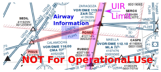
Figure 10.22: Exercise: En-Route Chart.1) En route Chart: Information is provided in Figure 10.22. The delimitation of UIR regions is marked therein. Yet, a track of airway UN870 between PISUS and PONEM is analysed. Information on that particular track is boxed. The name of the airway (UN870), the magnetic direction (\(70^{\circ}\)), the minimum FL (FL245, corresponding to upper airspace), and the distance between waypoints (42 NM) can be readily identified. Moreover the > marker indicates that the airway can be only flown in that particular direction. In order to know the flight levels that are permitted, one has to check the ATS basic RNAV routes in the AIP (ENR 3 - ATS routes). In this particular case, EVEN FLs are only permitted.
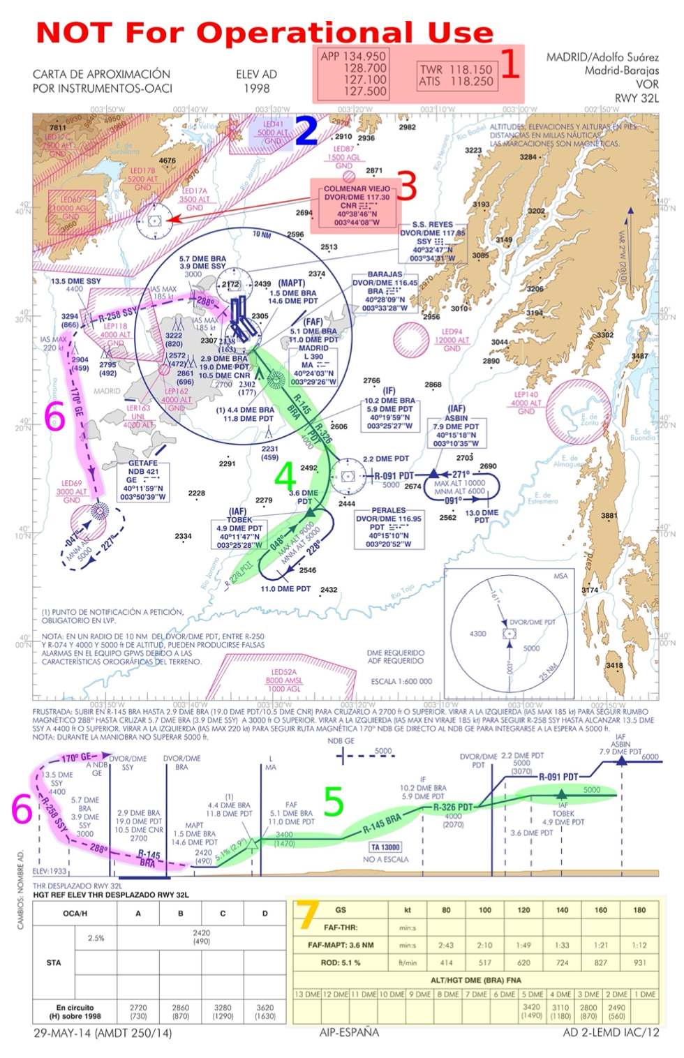
Figure 10.23: Instrumental app. chart: APP to Adolfo Suarez Madrid Barajas, RWY 32L.2) Final approximation chart: Notice that this is a non-precision approach (a non ILS approach). Check both the text with descriptions and Figure 10.23.
1) Frequencies for the APP control (e.g., 134.950), TWR control, and AFIS service. These should be tuned on-board to communicate with ATC.
2) Terrain map with altitude in ft and P,D,R areas in pink and altitude restrictions. E.g., marked area LED41 in Figure 10.23 denotes a Dangerous (D) airspace between altitude 5000 ft and Ground.
3) Navaids: For the sake of simplicity, just Colmenar Viejo (labeled CNR) is herein highlighted in Figure 10.23. It can be observed the frequency to tune it (117.30), its geographic location in the map, its coordinates, and the typology (DVOR/DME).
4) Approach procedure: horizontal profile. Only the procedure starting at IAF (Initial Approach Fix) TOBEK is exposed. Aircraft take radial \(048^{\circ}\) (with respect to Perales (PDT)); reach IAF TOBEK (4.9 NM from DME Perales); then turn to reach Radial 326 (with respect to Perales), reach the Initial Fix (IF) at 10.2 NM and 5.9 NM with respect to DME Barajas (labeled BRA) and DME Perales, respectively; follow Radial 145 with respect to BRA; reach Final Approach Fix (FAF) at 5.1 NM from DME Barajas; proceed to runway.
5) Approach procedure: vertical profile. Similarly, TOBEK procedure is exposed. Aircraft level off at 5000 ft, overflying TOBEK; then descent following Radial 326 with respect to PDT to 4000 ft (2070 with respect to Ground), level-off and intercept the IF; then proceed down following Radial 145 with respect to BRA, level-off at 3400 ft and intercept FAF; from FAF onwards proceed down with a 5.1% slope.
6) The go-around procedure is highlighted in Figure 10.23. Notice that the Go-Around procedure starts at the MAPT (Mixed Approach Point).
7) Last but not least, in the Tables marked below in the chart one can observe times between FAF and MAPT (3.6 NM) and the rate of descent (ROD) required to maintain 5.1% slope at different Ground Speeds.3) SID and STAR Route: These questions are left as an open exercise to students. Notice that finding the information in the AIP is not straight forward, thus leaving the exercise open should help the student going through the process of finding the needed information in the AIP. For the interpretation of both SIDs and STAR, one can check for instance IVAO’s SID explanation20 and IVAO’s STAR explanation,21 respectively.
Consider an intended flight between airport A and B (e.g., Continental Europe) at time \(H\) of day \(D\). According to current operations, analyze:
- How the sketched air navigation services in Figure 10.4 would affect your intended flight plan at strategic level, i.e., months before Time H and Day D. What is the status of your flight plan? Which role do Communications, Navigation, and Surveillance play at this stage?
- How the sketched air navigation services in Figure 10.4 would affect your intended flight plan at pre-tactical, i.e., 1-2 days before operation up to three hours before Time H and Day D. What is the status of your flight plan? Which role do Communications, Navigation, and Surveillance play at this stage?
- How the sketched air navigation services in in Figure 10.4 would affect your intended flight plan during the tactical phase (pre-flight and execution), i.e., from 3 hours before departure to real time execution of the flight. What is the status of your flight plan? Which role do Communications, Navigation, and Surveillance play at this stage?
- Answer
-
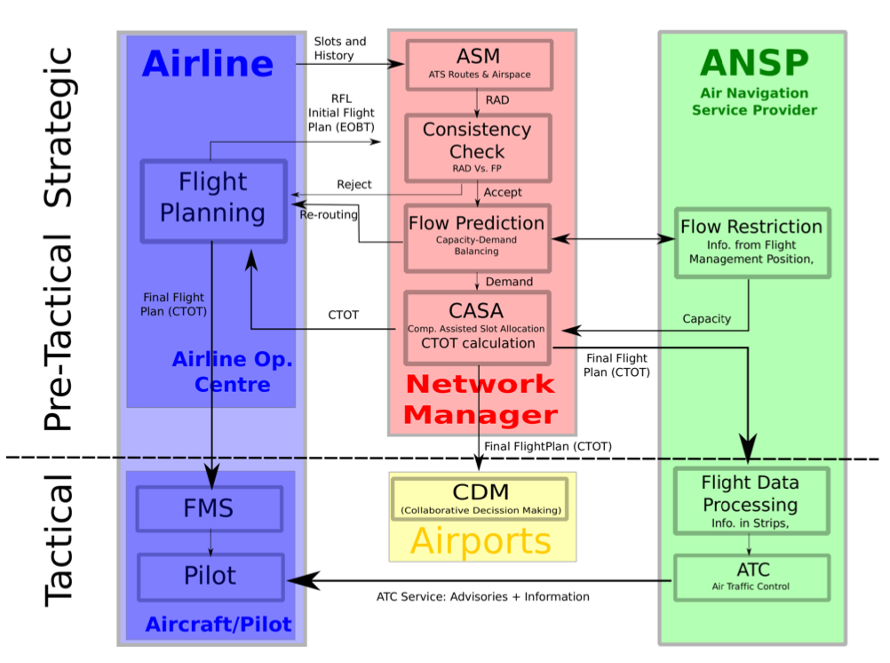
Figure 10.24L Flight Plan processes.Please, refer to the air navigation services sketched in Figure 10.4. Aditionally, all proceses in which a flight plan is involved are sketched in Figure 10.24. The following paragraphs try to assess (schematically) the proposes questions:
1) Strategic level
- First one should go into the process of coordination of slots and request one for Day D and Hour H. This should be done according to the season calendar (at least 6 months before departure). Please, refer to Figure 10.17 as an example.
- Assume you have got a slot. If your flight has certain periodicity, you will produce a repetitive flight plan. In order to do so, you must rely on the ASM, in particular on the availability of routes: check AIP for charts. Notice also that ATFM will publish a Route Availability Document (RAD) and your should also comply with it.
- The flight plan should be sent to ATFM (strategic layer) in order them to check that you flight plan is compliant with the structure of routes and the RAD document (consistency check). It could be rejected and thus returned to the flight operations center for further flight planning (also, suggestions of re-routing are typically issued) or accepted. Notice that the Flight Plan submission is a continuous process (you can submit as many time as you will) that might take place at strategic level, however it also exists (probably more intensively) at pre-tactical level.
- Notice that at this point Met Services are not very relevant, since forecast are only able to predict weather within one weak (with a lot of uncertainty though). Much more precise forecast will be made available at later stages of the process.
- CNS do not play an important role here: only notice that the network on routes has been (originally) built based on the existence of navaids located in certain geographical locations. Notice also that the whole structure of ATS routes is designed such that, later during the flight, CNS can be provided.
2) Pre-tactical level
- At this point, 1-2 days, the process is accelerated as time gets closer to departure. Notice that assuming IFR flight (typical of commercial aviation), three hours before departure one must send the flight plan to ATFM dependences. The Flight Plan will include a EOBT (Estimated off Block Time) that ATFM will use for its tactical planning (ATFM allocation of slots in following steps).
- At this stage, Met Service is very important, since much more accurate forecasts are available for both the flight operation center (for fine tuning of the flight plan, e.g., taking into consideration favourable winds) and the ANSP (e.g., identification of potential hazards that might affect capacity of the system).
- ATFM pre-tactical service will be in charge of analysing the capacity of the different sectors in the Network. It will gather information from the Flow Management Positions (1 per sector), Met information, any issue that might appear as a NOTAM, etc. An ATFM Notification Message will be produced including all regulations (capacity restrictions) that apply for the next day. This information might be relevant to flight dispatching to re-do the flight plan if needed.
- CNS: Do not play any important role at this time (just as before)
3) Tactical phase (pre-flight and execution)
- ATFM would at this stage (2-3 Hours before departure) balance capacity and demand. Demand will be given by all submitted flight plans (notice that 3 hours before departure no more flight plans will be admitted) and capacity regulations (included in the ATFM notification messages). ATFM will approve or delay the flight. In any case, ATFM will provide a Calculated Take Off Time (CTOT) (EOBT + taxi + possibly a delay).
- As for MET, short time forecasts and real time information is very relevant at this stage. It is important to distribute Information for pilots and controllers (e.g., METARs) to take demissions before departing and during the flight. In particular, wind direction and intensity will be the driver for the operational configuration (operational runway heads) of both departure and destination airport. This might be helpful to choose SID and STAR (Check AIP). Also, en-route weather hazards must be avoided during the flight.
- Regarding ATS, they are of course very relevant before departure and during the flight: agreeing changes (Pilot-controller) in the intended flight plan; advising manoeuvres in case of potential conflict or weather hazard; using FIS in case any relevant information; ALS might get activated in case of emergency.
- Finally, CNS do play a very important role during execution. Regarding communications, one should consider both fixed service (flight plan submissions to all ATC sectors) and mobile service (voice and data link communications). Regarding navigation systems, they are fundamental to know where the aircraft is and how to follow the route (VOR, DME, etc. are relevant both in Conventional Nav. and RNAV; the information is presented to the pilot using on-board cockpit instruments). As for surveillance systems, they are aimed at providing controllers with the information of the aircraft (position, altitude, velocity, etc.) in their screens (controller working position) to monitor its evolution inflight and, if needed, instruct them the appropriate manoeuvre.
Consider 8 aircraft that all depart at the same time T from different airports. All Aircraft have sent its intended flight plans before departure (at T-3H). Tactical ATFM is in charge of analysing whether the routes are compliant with the network of routes (they are) and asses any potential imbalances during the execution of the flight. Conditions of the problem are:
- According to the different FMP, capacity in Sectors I, II, III, IV, and V is 2 at any time.
- Stars correspond to the intended position of \(Acj (j = 1,...,8)\) at a future time \(T+3h\). Note that the size of the aircraft has been artificially overemphasised.
- Squares correspond to the entry/exit waypoints to sectors.
- Distances are (all units in km):
Airway a) \(A - AC1 = 5; Ac1 - C = 45; C - Ac2 = 5; Ac2 - J = 50\);
Airway b) \(M - B = 50; B - Ac6 = 10; Ac6 - D = 35; D - Ac7 = 10; Ac7 - E = 25\);
Airway c) \(G - Ac3 = 5; Ac3 - Ac4 = 20; Ac4 - H = 25; H - Ac5 = 10; Ac 5 - I = 50\);
Airway d) \(F - L = 35; L - Ac8 = 5; Ac8 - K = 50\);
- All aircraft fly at the same speed: \(200\ km/h\).
The questions are the following:
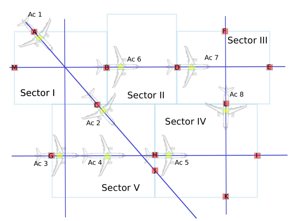
Figure 10.25: ATFM layout
- Is demand balanced with capacity (consider not only \(T+3H\), but all the potential times in which the aircraft would be overflying Sectors I to V)? If yes, identify capacity imbalances.
- According to the given layout in Figure 10.25 (and acting in the same way as the tactical ATFM faces this issue today), quantitatively assess the measures that should be taken into account (come up with a solution trying to minimise disruptions in the intended flight plans).
- Answer
-
We should first check whether there exist capacity imbalances. In order to do that, we should analyse the status of the aircraft at different time instants both before and after the snapshot time (\(T+3H\)). The reader should note that this is an ATFM related exercise, i.e., the picture showed represents a simulation of what is supposed to happen (according to submitted flight plans) at time T+3H. What ATFM does (among other issues) is to simulate all submitted flight plans and check for capacity-demand imbalances.
We thus simulate at three different instants of time, namely: \(T+3H-3\) min; \(T+3H-1.5\) min; \(T+3H+7.5\) min; and \(T+3H+15\) min. We evaluate the demand (number of aircraft) in each Sector (notice that an aircraft at interSector position is considered to belong to both sectors). The count is as follows:
- \(T + 3H - 3\) min (notice that aircraft fly 10 km in 3 min):
- Ac2 in S.I; Ac6 @ B (SECTOR I)
- Ac2 @ B; Ac7 @ D (SECTOR II)
- Ac7 @ D; Ac 8 IN S.III (SECTOR III)
- Ac5 @ H (SECTOR IV)
- Ac 4 in S.V; Ac5 @ H (SECTOR V) - \(T + 3H - 1.5\) min (notice that aircraft fly 5 km in 1.5 min):
- Ac1 @ A; Ac2 @ C (SECTOR I)
- Ac6 in S.II (SECTOR II)
- Ac7 in S.III; Ac8 @ L (SECTOR III)
- Ac5 in S.IV; Ac8 @ L (SECTOR IV)
- Ac3 @ G; Ac2 @ C; Ac4 in S.V (SECTOR V) - \(T + 3H + 7.5\) min (notice that aircraft fly 25 km in 7.5 min):
- Ac1 in S.I (SECTOR I)
- Ac6 in S.II (SECTOR II)
- Ac7 @ E (SECTOR III)
- Ac5 in S.IV; Ac8 in S.IV; Ac4 @ H (SECTOR IV)
- Ac3 in S.V; Ac2 in S.V (SECTOR V) - \(T + 3H + 15\) min (notice that aircraft fly 50 km in 15 min):
- (SECTOR I)
- (SECTOR II)
- Ac6 in S.III (SECTOR III)
- Ac5 @ I; Ac4 in S.IV; Ac3 in S.IV; Ac8 @ K; Ac2 @ J (SECTOR IV)
- Ac1 in S.V; Ac2 @ J (SECTOR V)
Given that the capacity of each sector at any time is 2, it can be readily observed that it is exceeded. Current ATFM studies run the so-called CASA (computer assisted slot allocation) software to balance capacity and demand, essentially a first come-first serve algorithm, that computes the CTOT time imposing ground delays to the "last come" aircraft. The purpose herein is not to replicate the CASA algorithm, but provide a solution that balances demand with capacity. The following is proposed: to delay on ground Ac 4 more that 7.5 min (e.g., 8 min); to delay Ac 3 more that 16.5 min (e.g., 17 min); to delay Ac 2 less that 1.5 min (e.g., 1 min); and to delay Ac 1 more that 1.5 min (e.g., 2 min).
Let us now analyze demand with this new CTOTs (after imposing the proposed delays) at the problematic times and thereafter:
- \(T + 3H + 15\) min \(\to\)
- Ac1 in S.I (SECTOR I)
- (SECTOR II)
- Ac6 in S.III (SECTOR III)
- Ac5 @ I; Ac8 @ K (SECTOR IV)
- Ac2 in S.V; Ac 4 in S.V (SECTOR V) - \(T + 3H + 18\) min \(\to\)
- (SECTOR I)
- (SECTOR II)
- Ac6 in S.III (SECTOR III)
- Ac2 in S.IV; Ac4 in S.IV (SECTOR IV)
- Ac1 in S.V; Ac3 in S.V (SECTOR V)
It can be seen that now demand does not go beyond the capacity (2 aircraft per sector at any time). The reader should notice that this solution is not intended to be exhaustive, computer assisted simulations are required to test whether this statement holds for all times. In any case, it should serve as example to understand how ATFM works.
- \(T + 3H - 3\) min (notice that aircraft fly 10 km in 3 min):
Consider 2 aircraft flying in the configuration sketched in Figure 10.26. ATC is in charge of avoiding any potential conflict during the flight. Conditions of the problem are:
- Ac.1 and Ac. 2 are stablished at constant FL.
- The executive controller in charge of the sector can advise aircraft to modify the speed (speed advisory). Note that no vertical manoeuvres nor vectoring (turn advisories) are considered.
- Stars correspond to the position of Ac 1 and Ac 2 at time t (t correspond to real time, i.e., the sketch is what the controller is seeing in her/his screen). Note that the size of the aircraft has been overemphasised.
- Distances are (all units in km): d1=60 km; d2= 40 km
- True Airspeeds are:22 \(V_{TAS_1}\) = 300 km/h; \(V_{TAS_2}\) = 200 Km/h. Unless ATC advisory, aircraft are supposed to keep constant speed and track.
- Loss of separation minima can be approximated to a distance of 10 Km.
The questions are the following:
- Is there any potential conflict envisioned?
- Assuming the controller wants to resolve the conflict with only one advisory (either to aircraft 1 or 2) and this advisory can be provided instantaneously at time t: Which speed advisory could be given?
- Answer
-
The equations of motion (taking the waypoint as the origin of coordinates) can be stated as follows:
\[x_1 = 60 - V_1 \cdot t \label{eq10.8.1} \]
\[y_1 = 0 \label{eq10.8.2} \]
\[x_2 = 0 \label{eq10.8.3} \]
\[y_2 = 40 - V_2 \cdot t \label{eq10.8.4} \]
Let us calculate first the time to reach WP I for each of the aircraft:
\[t_{airc_1} = \dfrac{60}{300} = \dfrac{1}{5}\nonumber \]
\[t_{airc_2} = \dfrac{40}{200} = \dfrac{1}{5}\nonumber \]
Therefore, it is straightforward to see that there is potential conflict. Recall that a conflict will exist if the minimum distance is violated (in this case, we assume \(d_{\min}\) = 10 km).
The distance can be calculated as follows:
\[d^2 = x_1^2 + y_2^2\nonumber \]
By substituting \(x_1\) and \(y_2\) in Eq. \ref{eq10.8.1} - \ref{eq10.8.4} and setting \(d = 10\), one has a quadratic equation on \(t\):
\[5.1 + t^2 \cdot 130 - t \cdot 520 = 0\nonumber \]
Solving it one gets the time window in which we have the conflict:
\[t \in [0.1722, 0.2277]\nonumber \]
In order to avoid the conflict, we decide for instance to modify the airspeed of aircraft 1. In order to avoid any potential conflict, \(d \ge 10\); \(\forall t\), in particular \(d \ge 10\); \(\forall t \in [0.1722, 0.2277]\).
We have four options:
- accelerate or decelerate aircraft 1.
- accelerate or decelerate aircraft 2.
If we decide to decelerate any of the aircraft, we must impose that at the maximum time of the conflict interval, i.e., \(t = 0.2277\), \(d = 10\). Since we are reducing speed of one of the aircraft, it will fly slower and arrive later to the conflicting points. We must ensure that at the latest time it has not arrived yet. If we were to accelerate one of the aircraft, we would have to impose the minimum separation criteria at the soonest time of conflict.
The question that arises is: what is the correct strategy? In principle, any of them is valid. Notice however that, we might have problems related to a converging relative velocity.
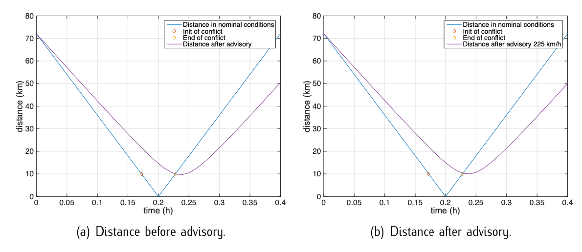
Figure 10.27: Solution to ATC exercise.For instance, if we decide to decelerate aircraft 1 and impose that at the maximum time of the conflict interval, i.e., \(t = 0.2277\), \(d = 10\), substituting we get a quadratic equation on V1, which solution yields 226.94 km/h (the other solution is 300 km/h, i.e., not touching the aircraft). In this case, since aircraft 1 is still flying faster than aircraft 2, we can not ensure that there is no conflict afterwards. Indeed there is. Figure 10.27.a illustrates the solution.
If we lower the velocity to 225 km/h, then there is no conflict anymore. Figure 10.27.b illustrates the solution.
20. https://www.ivao.aero/training/docum...SID_charts.pdf
21. https://www.ivao.aero/training/docum...TAR_charts.pdf
22. note that wind can be neglected