
11.3.2: Non autonomous systems
- Page ID
- 78394

\( \newcommand{\vecs}[1]{\overset { \scriptstyle \rightharpoonup} {\mathbf{#1}} } \)
\( \newcommand{\vecd}[1]{\overset{-\!-\!\rightharpoonup}{\vphantom{a}\smash {#1}}} \)
\( \newcommand{\dsum}{\displaystyle\sum\limits} \)
\( \newcommand{\dint}{\displaystyle\int\limits} \)
\( \newcommand{\dlim}{\displaystyle\lim\limits} \)
\( \newcommand{\id}{\mathrm{id}}\) \( \newcommand{\Span}{\mathrm{span}}\)
( \newcommand{\kernel}{\mathrm{null}\,}\) \( \newcommand{\range}{\mathrm{range}\,}\)
\( \newcommand{\RealPart}{\mathrm{Re}}\) \( \newcommand{\ImaginaryPart}{\mathrm{Im}}\)
\( \newcommand{\Argument}{\mathrm{Arg}}\) \( \newcommand{\norm}[1]{\| #1 \|}\)
\( \newcommand{\inner}[2]{\langle #1, #2 \rangle}\)
\( \newcommand{\Span}{\mathrm{span}}\)
\( \newcommand{\id}{\mathrm{id}}\)
\( \newcommand{\Span}{\mathrm{span}}\)
\( \newcommand{\kernel}{\mathrm{null}\,}\)
\( \newcommand{\range}{\mathrm{range}\,}\)
\( \newcommand{\RealPart}{\mathrm{Re}}\)
\( \newcommand{\ImaginaryPart}{\mathrm{Im}}\)
\( \newcommand{\Argument}{\mathrm{Arg}}\)
\( \newcommand{\norm}[1]{\| #1 \|}\)
\( \newcommand{\inner}[2]{\langle #1, #2 \rangle}\)
\( \newcommand{\Span}{\mathrm{span}}\) \( \newcommand{\AA}{\unicode[.8,0]{x212B}}\)
\( \newcommand{\vectorA}[1]{\vec{#1}} % arrow\)
\( \newcommand{\vectorAt}[1]{\vec{\text{#1}}} % arrow\)
\( \newcommand{\vectorB}[1]{\overset { \scriptstyle \rightharpoonup} {\mathbf{#1}} } \)
\( \newcommand{\vectorC}[1]{\textbf{#1}} \)
\( \newcommand{\vectorD}[1]{\overrightarrow{#1}} \)
\( \newcommand{\vectorDt}[1]{\overrightarrow{\text{#1}}} \)
\( \newcommand{\vectE}[1]{\overset{-\!-\!\rightharpoonup}{\vphantom{a}\smash{\mathbf {#1}}}} \)
\( \newcommand{\vecs}[1]{\overset { \scriptstyle \rightharpoonup} {\mathbf{#1}} } \)
\(\newcommand{\longvect}{\overrightarrow}\)
\( \newcommand{\vecd}[1]{\overset{-\!-\!\rightharpoonup}{\vphantom{a}\smash {#1}}} \)
\(\newcommand{\avec}{\mathbf a}\) \(\newcommand{\bvec}{\mathbf b}\) \(\newcommand{\cvec}{\mathbf c}\) \(\newcommand{\dvec}{\mathbf d}\) \(\newcommand{\dtil}{\widetilde{\mathbf d}}\) \(\newcommand{\evec}{\mathbf e}\) \(\newcommand{\fvec}{\mathbf f}\) \(\newcommand{\nvec}{\mathbf n}\) \(\newcommand{\pvec}{\mathbf p}\) \(\newcommand{\qvec}{\mathbf q}\) \(\newcommand{\svec}{\mathbf s}\) \(\newcommand{\tvec}{\mathbf t}\) \(\newcommand{\uvec}{\mathbf u}\) \(\newcommand{\vvec}{\mathbf v}\) \(\newcommand{\wvec}{\mathbf w}\) \(\newcommand{\xvec}{\mathbf x}\) \(\newcommand{\yvec}{\mathbf y}\) \(\newcommand{\zvec}{\mathbf z}\) \(\newcommand{\rvec}{\mathbf r}\) \(\newcommand{\mvec}{\mathbf m}\) \(\newcommand{\zerovec}{\mathbf 0}\) \(\newcommand{\onevec}{\mathbf 1}\) \(\newcommand{\real}{\mathbb R}\) \(\newcommand{\twovec}[2]{\left[\begin{array}{r}#1 \\ #2 \end{array}\right]}\) \(\newcommand{\ctwovec}[2]{\left[\begin{array}{c}#1 \\ #2 \end{array}\right]}\) \(\newcommand{\threevec}[3]{\left[\begin{array}{r}#1 \\ #2 \\ #3 \end{array}\right]}\) \(\newcommand{\cthreevec}[3]{\left[\begin{array}{c}#1 \\ #2 \\ #3 \end{array}\right]}\) \(\newcommand{\fourvec}[4]{\left[\begin{array}{r}#1 \\ #2 \\ #3 \\ #4 \end{array}\right]}\) \(\newcommand{\cfourvec}[4]{\left[\begin{array}{c}#1 \\ #2 \\ #3 \\ #4 \end{array}\right]}\) \(\newcommand{\fivevec}[5]{\left[\begin{array}{r}#1 \\ #2 \\ #3 \\ #4 \\ #5 \\ \end{array}\right]}\) \(\newcommand{\cfivevec}[5]{\left[\begin{array}{c}#1 \\ #2 \\ #3 \\ #4 \\ #5 \\ \end{array}\right]}\) \(\newcommand{\mattwo}[4]{\left[\begin{array}{rr}#1 \amp #2 \\ #3 \amp #4 \\ \end{array}\right]}\) \(\newcommand{\laspan}[1]{\text{Span}\{#1\}}\) \(\newcommand{\bcal}{\cal B}\) \(\newcommand{\ccal}{\cal C}\) \(\newcommand{\scal}{\cal S}\) \(\newcommand{\wcal}{\cal W}\) \(\newcommand{\ecal}{\cal E}\) \(\newcommand{\coords}[2]{\left\{#1\right\}_{#2}}\) \(\newcommand{\gray}[1]{\color{gray}{#1}}\) \(\newcommand{\lgray}[1]{\color{lightgray}{#1}}\) \(\newcommand{\rank}{\operatorname{rank}}\) \(\newcommand{\row}{\text{Row}}\) \(\newcommand{\col}{\text{Col}}\) \(\renewcommand{\row}{\text{Row}}\) \(\newcommand{\nul}{\text{Nul}}\) \(\newcommand{\var}{\text{Var}}\) \(\newcommand{\corr}{\text{corr}}\) \(\newcommand{\len}[1]{\left|#1\right|}\) \(\newcommand{\bbar}{\overline{\bvec}}\) \(\newcommand{\bhat}{\widehat{\bvec}}\) \(\newcommand{\bperp}{\bvec^\perp}\) \(\newcommand{\xhat}{\widehat{\xvec}}\) \(\newcommand{\vhat}{\widehat{\vvec}}\) \(\newcommand{\uhat}{\widehat{\uvec}}\) \(\newcommand{\what}{\widehat{\wvec}}\) \(\newcommand{\Sighat}{\widehat{\Sigma}}\) \(\newcommand{\lt}{<}\) \(\newcommand{\gt}{>}\) \(\newcommand{\amp}{&}\) \(\definecolor{fillinmathshade}{gray}{0.9}\)Non autonomous systems require the information generated by terrestrial stations or satellites to determine the position, course, and/or velocity of the aircraft. In this manner, the transmission station (transmitter) produces electromagnetic waves that are received in the reception point (receptor).
The supplied information is referred to as observables (it can be a distance, a course, etc.). Such information locates the aircraft inside a so-called situation surface, i.e., if the observable is the distance, one knows that the aircraft is located at some point on the surface of a sphere with center the transmission center.
More precisely, a situation surface is the geometric locus of the space which is compatible with the observables. The types of situation surfaces are:
- Plane perpendicular to the surface of earth where the aircraft is located. The observable is the course.
- Spherical surface with the center in the transmission station. The observable is the distance.
- Hyperboloid of revolution, being the focuses two external transmission centers exchanging information. The observable is the distance.
In general, using information coming only from one transmitter, it is impossible to locate an aircraft; more sources of information are needed. If two surfaces are intersected,
one obtains a curve. If three (or more) surfaces are intersected, one obtains a point (if more than three, ideally also a point). Therefore, in order to locate an aircraft one needs either two transmitter (generating two surfaces) plus the altitude given by the altimeter, or three transmitters (generating three surfaces).
We turn now the discussion to analyze how such observables are obtained, i.e., how we are able to determine a distance or a course using terrestrial stations or satellites. They are obtained using different techniques based on electromagnetic fields, namely:
- Radiotelemetry.
- Radiogoniometry.
- Scanning beam.
- Spatial modulation.
- Doppler effect.
Radiotelemetry: It is based on the consideration that the electromagnetic waves travel at constant velocity, the velocity of light (c = 300000 km/s), and in straight line8. Under these assumptions, if we measure the time that the waves take from the instant in which the transmitter emits the wave and it receives it back after being rebooted by the receptor (the aircraft), by simple kinematic analysis one can obtain the distance.
Radiogoniometry: It is based on the consideration that the electric and magnetic field that constitute an electromagnetic wave are both perpendicular to the direction of propagation of the wave. Using this technique, by measuring the phases of the electric and magnetic fields of the wave, one can determine the angle that forms the longitudinal axis of the aircraft with the direction of the transmitted wave.
Scanning beam: It is based on the fact that the electromagnetic wave emitted by the transmitter has a dynamic radiation diagram9, with a narrow principal lobe and very small secondary lobes. The receptor (aircraft) is only illuminated (radiated) if the principal lobe points to the aircraft. In this way, knowing the movement law of the radiation diagram, when the aircraft is illuminated one can obtain the direction between the transmitter and the aircraft.
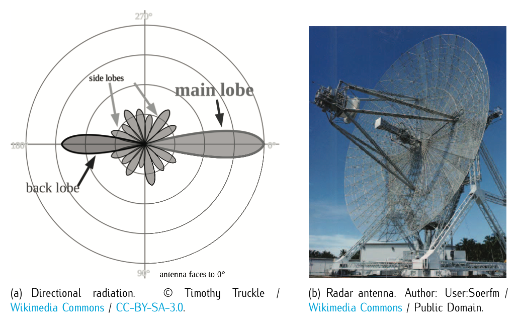
Figure 11.6: Scanning beam radiation diagram and a radar antenna that produces a directional radiation. Notice that the radar is a surveillance system.
Spatial modulation: This technique is original from air navigation. Two different electromagnetic waves are used. The first one is the reference signal, generating an omnidirectional magnetic field so that all points of the region receive the same information. These kind of antennas are referred to as isotropic antennas, and their radiation is referred to as isotropic or omnidirectional radiation. The second signal generates a (either static or dynamic) directional magnetic field. The comparison between the phases of the reference signal and the directional signal determines the direction of the aircraft.
Doppler effect: It is based on the change of frequency of a wave produced by the relative movement of the generating source (transmitter) with respect to the receiver (aircraft). In this way, one can obtain the distance between transmitter and aircraft.
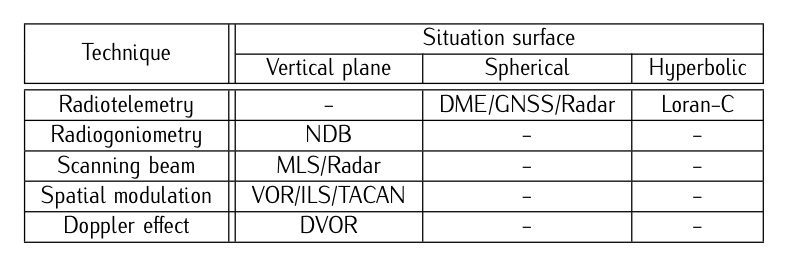
Table 11.2: Navigation aids based on situation surface and the technique.
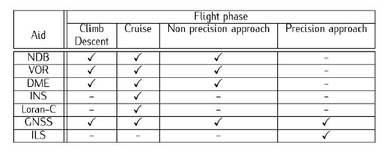
Table 11.3: Classification of the navigation aids based on the flight phase.
Table 11.2 and Table 11.3 show a classification of the different navigation aids as a function of the different techniques and the different situation surfaces, and a classification of the different navigation aids as a function of the different flight phases, respectively.
The most important ones using the technique of radiotelemetry are of two kinds: those that locate the aircraft in spheres; those that locate the aircraft in revolution hyperboloids. The most important ones among the first ones are: DME (Distance Measurement Equipment); TACAN (TACtical Air Navigation equipment)10, typically used in military aviation; GNSS (Global Navigation Satellites Systems); Radar11 (Radio detection and ranging)12. Due to its importance, we will just analyze more in depth the DME and the GNSS systems. Radiotelemetry is also used in another way by the so called hyperbolic systems (those systems that locate the aircraft in revolution hyperboloids): LORAN-C, Omega, DECCA. None of them is being used nowadays. Due to its historial importance, we will focus on LORAN-C.
Regarding the navigational aids that use the technique of radiogoniometry, the most important one is: NDB (Non-Directional (radio) Beacon).13 For those using Spatial modulation, the most important ones are: VOR (VHF Omnidirectional Radio range); ILS (Instrument Landing System). The ILS has been already studied in Chapter 9. We will focus on the VOR14. Finally, we will analyze the navigational aids that use Scanning beam. This technique is based on concentrating the radiation of electromagnetic waves in a particular direction. Big antennas and high frequencies must be used. The most important systems are: MLS (Microwave landing system); Radar (radio detection and ranging).
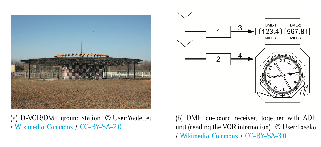
Figure 11.7: VOR-DME.
8. Notice that the fact that the light travels in a straight line was proven false in Einstein’s theory of general relativity. Inside the atmosphere (using terrestrial transmitter with aircraft as receptors) one can assume as hypothesis a straight line. When using satellites, the trajectory is a curve and the straight line must be corrected.
9. A diagram of radiation is a graphic representation of the intensity of a radiated signal in each direction. In some cases, there exist a principle lob and secondary lobs of less intensity.
10. Equivalent to the use together of a VOR and a DME.
11. This system uses both radiotelemetry and scanning beam techniques.
12. this system is specific of the surveillance and it will be analyzed later on.
13. The on-board equipment that captures the information is called Automatic Direction Finder (ADF). Thus, sometimes, these equipments are named as a whole as NDB-ADF.
14. Source: Wikipedia: VOR