3.5: The Tear Type and Chip Type
- Page ID
- 29433
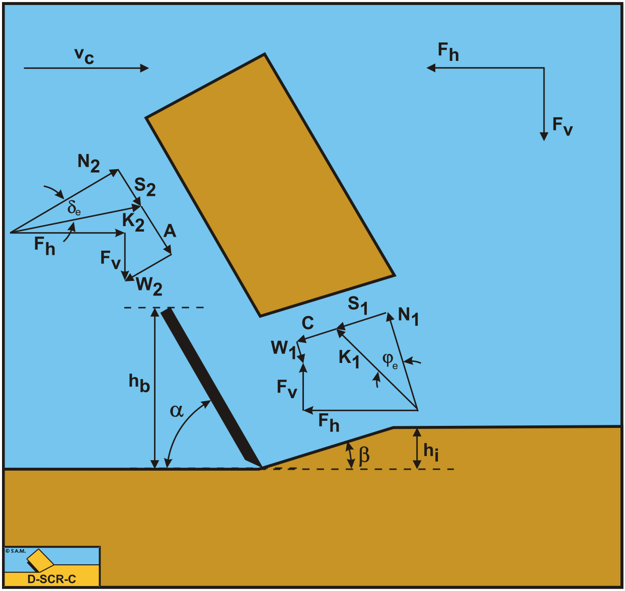
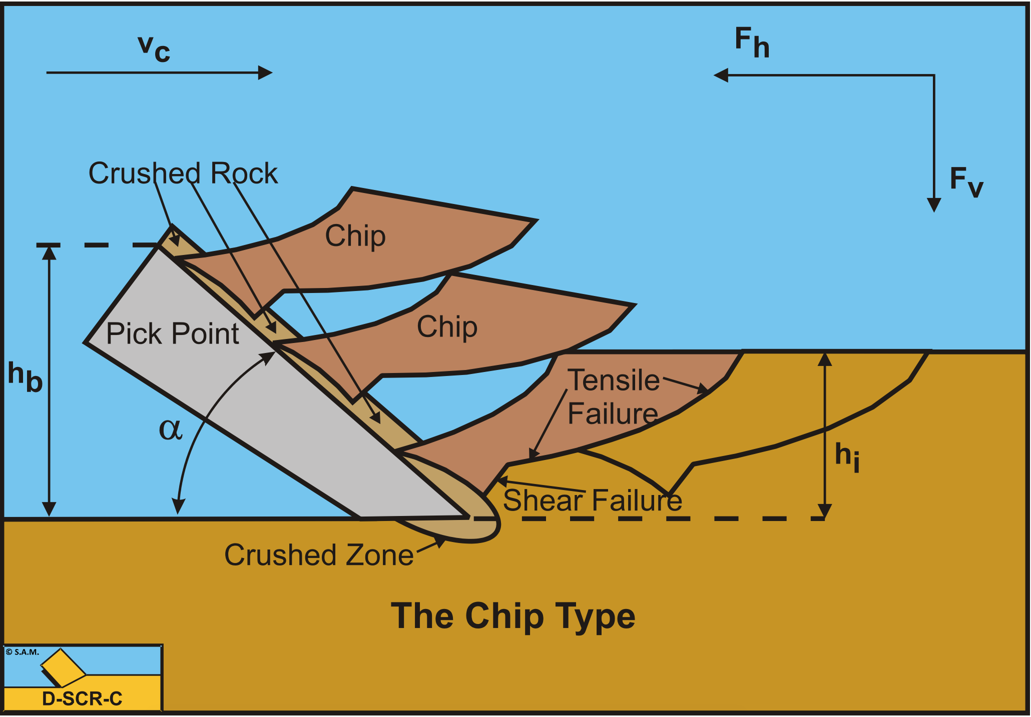
The Tear Type of cutting process has a failure mechanism based on tensile failure. For such a failure mechanism to occur it is required that negative stresses may occur. In sand this is not the case, because in sand the failure lines according to the Mohr-Coulomb criterion will pass through the origin as is shown in Figure 2-46 and Figure 2-47. For the failure lines not to pass through the origin it is required that the soil has a certain cohesion or shear strength like with clay and rock. In clay and rock, normally, the inertial forces and the gravity can be neglected and also the water pore pressures do not play a role. Only with hyperbaric rock cutting the water pore pressures will play a role, but there the Tear Type will not occur. This implies that for the Tear Type and Chip Type a soil with cohesion and adhesion and internal and external friction will be considered.
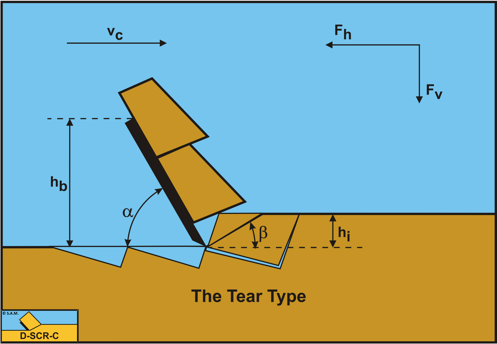
If clay or rock is considered, the following condition can be derived with respect to tensile rupture:
With the relations for the cohesive force C, the adhesive force A and the adhesion/cohesion ratio r (the ac ratio r):
\[\ \mathrm{C}=\frac{\lambda_{\mathrm{s}} \cdot \mathrm{c} \cdot \mathrm{h}_{\mathrm{i}} \cdot \mathrm{w}}{\sin (\beta)}\tag{3-26}\]
\[\ \mathrm{A=\frac{\lambda_{s} \cdot a \cdot h_{b} \cdot w}{\sin (\alpha)}}\tag{3-27}\]
\[\ \mathrm{r}=\frac{\mathrm{a} \cdot \mathrm{h}_{\mathrm{b}}}{\mathrm{c} \cdot \mathrm{h}_{\mathrm{i}}}\tag{3-28}\]
The horizontal Fh and vertical Fv cutting forces can be determined according to:
\[\ \mathrm{F_{\mathrm{h}}=\lambda_{\mathrm{s}} \cdot c \cdot h_{\mathrm{i}} \cdot w \cdot \frac{\frac{\sin (\alpha+\delta)}{\sin (\beta)} \cdot \cos (\varphi)+r \cdot \frac{\sin (\beta+\varphi)}{\sin (\alpha)} \cdot \cos (\delta)}{\sin (\alpha+\beta+\delta+\varphi)}}\tag{3-29}\]
\[\ \mathrm{F}_{v}=\mathrm{\lambda_{s} \cdot c \cdot h_{i} \cdot w \cdot \frac{\frac{\cos (\alpha+\delta)}{\sin (\beta)} \cdot \cos (\varphi)-r \cdot \frac{\cos (\beta+\varphi)}{\sin (\alpha)} \cdot \cos (\delta)}{\sin (\alpha+\beta+\delta+\varphi)}}\tag{3-30}\]
The shear angle β is determined in the case where the horizontal cutting force Fh is at a minimum, based on the minimum energy principle.
\[\ \begin{array}{left} \frac{\partial \mathrm{F}_{\mathrm{h}}}{\partial \boldsymbol{\beta}}&= \frac{\mathrm{r} \cdot \cos (\delta) \cdot \sin (\mathrm{2} \cdot \boldsymbol{\beta}+\varphi) \cdot \sin (\alpha) \cdot \sin (\beta) \cdot \sin (\alpha+\beta+\delta+\varphi)}{\sin ^{2}(\alpha+\beta+\delta+\varphi) \cdot \sin ^{2}(\alpha) \cdot \sin ^{2}(\beta)} \\
&+\frac{-\sin (\alpha) \cdot \sin (\alpha+2 \cdot \beta+\delta+\varphi) \cdot(\sin (\alpha) \cdot \sin (\alpha+\delta) \cdot \cos (\varphi))}{\sin ^{2}(\alpha+\beta+\delta+\varphi) \cdot \sin ^{2}(\alpha) \cdot \sin ^{2}(\beta)} =0 \\
&+\frac{-\sin (\alpha) \cdot \sin (\alpha+2 \cdot \beta+\delta+\varphi) \cdot(\mathrm{r} \cdot \sin (\beta) \cdot \sin (\beta+\varphi) \cdot \cos (\delta))}{\sin ^{2}(\alpha+\beta+\delta+\varphi) \cdot \sin ^{2}(\alpha) \cdot \sin ^{2}(\beta)} \end{array}\tag{3-31}\]
In the special case where there is no adhesion, r = 0 , the shear angle is:
\[\ \mathrm{\frac{\partial F_{h}}{\partial \beta}=\frac{-\sin (\alpha+2 \cdot \beta+\delta+\varphi) \cdot \sin (\alpha+\delta) \cdot \cos (\varphi)}{\sin ^{2}(\alpha+\beta+\delta+\varphi) \cdot \sin ^{2}(\beta)}=0}\tag{3-32}\]
So:
\[\ \sin (\alpha+2 \cdot \beta+\delta+\varphi)=0\text{ for }\alpha+2 \cdot \beta+\delta+\varphi=\pi\text{ giving }\beta=\frac{\pi}{2}-\frac{\alpha+\delta+\varphi}{2}\tag{3-33}\]
The cohesion c can be determined from the UCS value and the angle of internal friction φ according to (as is shown in Figure 3-12):
\[\ \mathrm{c=\frac{\mathrm{U} \mathrm{C S}}{2} \cdot\left(\frac{1-\sin (\varphi)}{\cos (\varphi)}\right)}\tag{3-34}\]
According to the Mohr-Coulomb failure criterion, the following is valid for the shear stress on the shear plane, as is shown in Figure 3-13.
\[\ \tau_{\mathrm{S} 1}=\mathrm{c}+\sigma_{\mathrm{N} 1} \cdot \tan (\varphi)\tag{3-35}\]
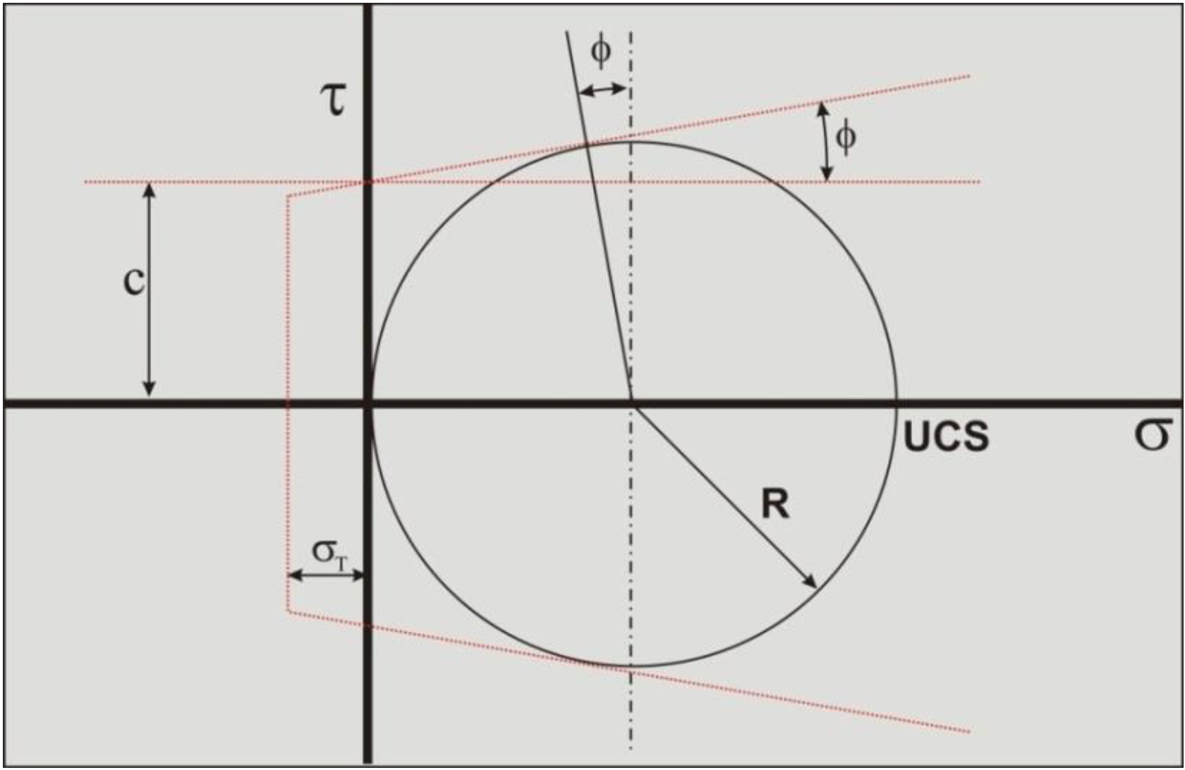
The average stress condition on the shear plane is now σN1, \(\ \tau_{\mathrm{S1}}\) as is show in Figure 3-13. A Mohr circle (Mohr circle 1) can be drawn through this point, resulting in a minimum stress σmin which is negative, so tensile. If this minimum normal stress is smaller than the tensile strength σT tensile fracture will occur, as is the case in the figure. Now Mohr circle 1 can never exist, but a smaller circle (Mohr circle 2) can, just touching the tensile strength σT. The question is now, how to get from Mohr circle 1 to Mohr circle 2. To find Mohr circle 2 the following steps have to be taken.
The radius R of the Mohr circle 1 can be found from the shear stress \(\ \tau_{\mathrm{S1}}\) by:
\[\ \mathrm{R=\frac{\tau_{\mathrm{S} 1}}{\cos (\varphi)}}\tag{3-36}\]
The center of the Mohr circle 1, σC, now follows from:
\[\ \begin{array}{left} \sigma_{\mathrm{C}}&=\mathrm{\sigma_{\mathrm{N} 1}+R \cdot \sin (\varphi)=\sigma_{\mathrm{N} 1}+\tau_{\mathrm{S} 1} \cdot \tan (\varphi)}\\
&=\mathrm{\sigma_{\mathrm{N} 1}+\mathrm{c} \cdot \tan (\varphi)+\sigma_{\mathrm{N} 1} \cdot \tan ^{2}(\varphi)}\end{array}\tag{3-37}\]
The normal force N1 on the shear plane is now:
\[\ \begin{aligned} \mathrm{N}_{1}=& \frac{-\mathrm{C} \cdot \cos (\alpha+\beta+\delta)+\mathrm{A} \cdot \cos (\delta)}{\sin (\alpha+\beta+\delta+\varphi)} \cdot \cos (\varphi) \\=& \lambda_{\mathrm{s}} \cdot \mathrm{c} \cdot \mathrm{h}_{\mathrm{i}} \cdot \mathrm{w} \cdot \frac{-\frac{\cos (\alpha+\beta+\delta)}{\sin (\beta)}+\mathrm{r} \cdot \frac{\cos (\delta)}{\sin (\alpha)}}{\sin (\alpha+\beta+\delta+\varphi)} \cdot \cos (\varphi) \end{aligned}\tag{3-38}\]
The normal stress σN1 on the shear plane is:
\[\ \begin{array}{left} \sigma_{\mathrm{N} 1}&=\frac{\mathrm{N}_{1} \cdot \sin (\beta)}{\mathrm{h}_{\mathrm{i}} \cdot \mathrm{w}} \\&= \lambda_{\mathrm{s}} \cdot \mathrm{c} \cdot \frac{-\frac{\sin (\beta) \cdot \cos (\alpha+\beta+\delta)}{\sin (\beta)}+\mathrm{r} \cdot \frac{\sin (\beta) \cdot \cos (\delta)}{\sin (\alpha)}}{\sin (\alpha+\beta+\delta+\varphi)} \cdot \cos (\varphi) \end{array}\tag{3-39}\]
The minimum principal stress σmin equals the normal stress in the center of the Mohr circle σC minus the radius of the Mohr circle R:
\[\ \sigma_{\min }=\sigma_{\mathrm{C}}-\mathrm{R}=\sigma_{\mathrm{N} 1}+\mathrm{c} \cdot \tan (\varphi)+\sigma_{\mathrm{N} 1} \cdot \tan ^{2}(\varphi)-\frac{\mathrm{c}}{\cos (\varphi)}-\frac{\sigma_{\mathrm{N} 1} \cdot \tan (\varphi)}{\cos (\varphi)}\tag{3-40}\]
Rearranging this gives:
\[\ \sigma_{\min }=\sigma_{\mathrm{N} 1} \cdot\left(1+\tan ^{2}(\varphi)-\frac{\tan (\varphi)}{\cos (\varphi)}\right)+\mathrm{c} \cdot\left(\tan (\varphi)-\frac{1}{\cos (\varphi)}\right)\tag{3-41}\]
\[\ \begin{array}{left} \sigma_{\min } &=\frac{\sigma_{\mathrm{N} 1}}{\cos (\varphi)} \cdot\left(\frac{\cos ^{2}(\varphi)+\sin ^{2}(\varphi)-\sin (\varphi)}{\cos (\varphi)}\right)-\mathrm{c} \cdot\left(\frac{1-\sin (\varphi)}{\cos (\varphi)}\right) \\ &=\left(\frac{\sigma_{\mathrm{N} 1}}{\cos (\varphi)}-\mathrm{c}\right) \cdot\left(\frac{1-\sin (\varphi)}{\cos (\varphi)}\right) \end{array}\tag{3-42}\]
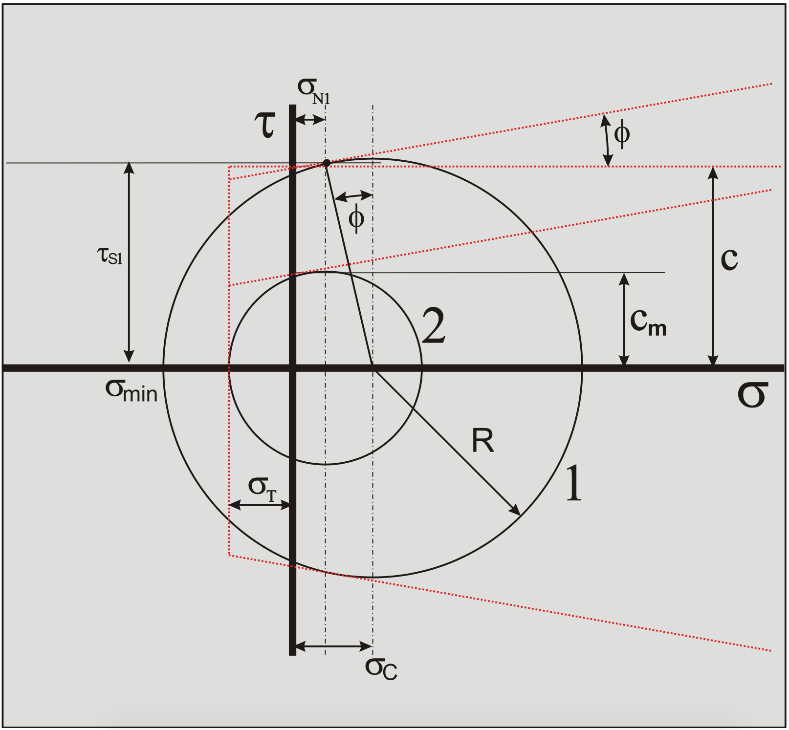
Now ductile failure will occur if the minimum principal stress σmin is bigger than then tensile strength σT, thus:
\[\ \sigma_{\min }>\sigma_{\mathrm{T}}\tag{3-43}\]
If equation (3-43) is true, ductile failure will occur. Keep in mind however, that the tensile strength σT is a negative number. Of course if the minimum normal stress σmin is positive, brittle tensile failure can never occur.
Substituting equation (3-39) for the normal stress on the shear plane gives the following condition for the Tear Type:
\[\ \mathrm{c \cdot\left(\frac{r \cdot \frac{\sin (\beta) \cdot \cos (\delta)}{\sin (\alpha)}-\cos (\alpha+\beta+\delta)-\sin (\alpha+\beta+\delta+\varphi)}{\sin (\alpha+\beta+\delta+\varphi)}\right) \cdot\left(\frac{1-\sin (\varphi)}{\cos (\varphi)}\right)>\sigma_{T}}\tag{3-44}\]
In clay it is assumed that the internal and external friction angles are zero, while in rock it is assumed that the adhesion is zero. This will be explained in detail in the chapters on clay and rock cutting.
The ratios between the pore pressures and the cohesive shear strength, in the case of hyperbaric rock cutting, can be found according to:
\[\ \begin{array}{left}\mathrm{r=\frac{a \cdot h_{b}}{c \cdot h_{i}}, r_{1}=\frac{p_{1 m} \cdot h_{i}}{c \cdot h_{i}}\text{ or }r_{1}=\frac{\rho_{w} \cdot g \cdot(z+10) \cdot h_{i}}{c \cdot h_{i}}}\\
\mathrm{r_{2}=\frac{p_{2 m} \cdot h_{b}}{c \cdot h_{i}}\text{ or }r_{2}=\frac{\rho_{w} \cdot g \cdot(z+10) \cdot h_{b}}{c \cdot h_{i}}}\end{array}\tag{3-45}\]
Equation (3-46) can be derived for the occurrence of tensile failure under hyperbaric conditions. Under hyperbaric conditions equation (3-46) will almost always be true, because of the terms with r1 and r2 which may become very big (positive). So tensile failure will not be considered for hyperbaric conditions.
\[\ \mathrm{c}\cdot \left(\begin{array}{left}\mathrm{r\cdot\frac{sin(\beta)\cdot cos(\delta)}{sin(\alpha)}+r_2 \cdot \frac{sin(\beta)\cdot sin(\delta)}{sin(\alpha)}+r_1 \cdot sin(\alpha + \beta+\delta)}\\ + \mathrm{\frac{-cos(\alpha + \beta + \delta)-sin(\alpha + \beta +\delta+\varphi)}{sin(\alpha+\beta+\delta+\varphi)}} \end{array} \right)\cdot \mathrm{\left(\frac{1-sin(\varphi)}{cos(\varphi)} \right)>\sigma_T }\tag{3-46}\]
Analyzing equations (3-44) and (3-46) gives the following conclusions:
-
The first term of equations (3-44) and (3-46) is always positive.
-
If the sum of α+β+δ>π/2, in the second term of equation (3-44) and the fourth term of equation (3-46), these terms are positive, which will be the case for normal cutting angles.
-
The second and third terms of equation (3-46) are always positive.
-
The last term in equations (3-44) and (3-46) is always negative.
-
Equation (3-44) may become negative and fulfill the condition for the Tear Type.
-
Equation (3-46) will never become negative under normal conditions, so under hyperbaric conditions the Tear Type will never occur.
-
The Tear Type may occur with clay and rock under atmospheric conditions.
