
5.2: Understanding the MSCPU
- Page ID
- 76115

To understand the MSCPU, explanations and illustrations of a how a number of assembly instructions are implemented will be provided.
3-address ADD operation
The first instruction is a 3-address ADD operation using two register values as input. An example is shown below and an explanation will explain how this instruction works in the MSCPU.
ADD Rd, Rn, Rm
The value of the Rm is passed on the B bus directly to the ALU, and the value of Rn is passed on the A bus directly to the ALU. The ALU calculates the result and passes the value back to the Register Bank where it is stored in Rd. Note because only one operation unit, the ALU, is used, this operation can be run in one cycle.
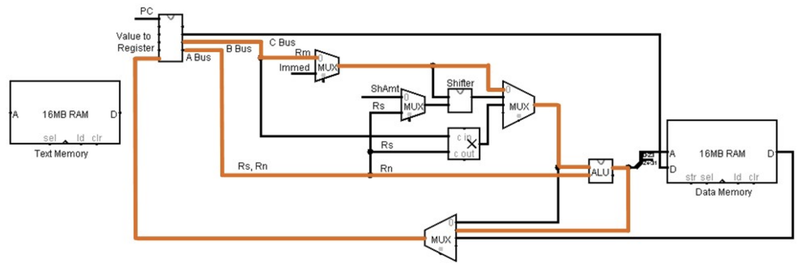
Figure 24: MSCPU ADD operation
LSL operation
The LSL operation is illustrated in the diagram below.
LSL r1, r2, #4
In this case the lsl operation uses the ShAmt (4) as input to the barrel shifter. The value on the B bus is the Rm register (r2). For a shift operation, the value from the shifter does not have to be sent to the ALU and so is passed directly to the mux to be selected and returned to the Register Bank to be stored in Rd (r1). Note, because only one operation unit, the barrel shifter, is used, this operation can be run in one cycle.
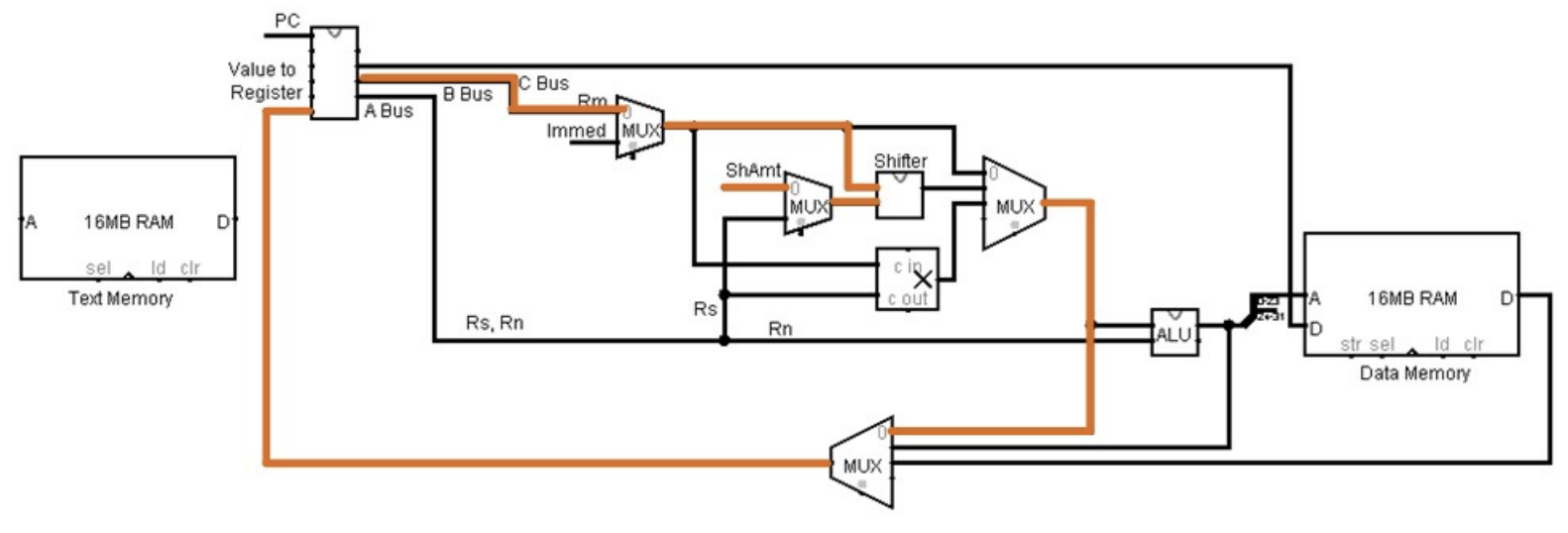
Figure 25: MSCPU LSL operation
MUL operation
The mul operation is illustrated in the diagram below.
mul r3, r1, r2
For this instruction, the registers Rm and Rs are used as input. As with the shift operation, the value from the multiplier does not have to be sent to the ALU, and so it is passed directly to the mux to be selected and returned to the Register Bank to be stored in Rd. Note, because only one operation unit, the multiplier, is used, this operation can be run in one cycle.
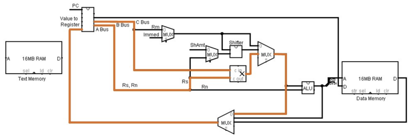
Figure 26: MSCPU MUL operation