
3.7: Pulse Compression
- Page ID
- 49024

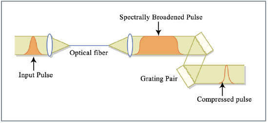
So far we have discussed propagation of a pulse in negative dispersive media and positive self-phase modulation. Then at large enough pulse energy a soliton can form, because the low and high frequency components generated by SPM in the front and the back of the pulse are slow and fast and therefore catch up with the pulse and stay together. What happens if the dispersion is positive? Clearly, the low and high frequency components generated by SPM in the front and back of the pulse are fast and slow and move away from the pulse in a continuous fashion. This leads to highly but linearly chirped pulse, which can be compressed after the nonlinear propagation by sending it through a linear negative dispersive medium or prism pair or grating pair. In that way, pulses can be compressed by large factors of 3 to 20. This pulse compression process can be formulated in a more general way.
General Pulse Compression Scheme
The general scheme for pulse compression of optical pulses was independently proposed by Gires and Tournois in 1964 [38] and Giordmaine et al. in 1968 [39]. The input pulse is first spectrally broadened by a phase modulator. The phase over the generated spectrum is hopefully in a form that can be conveniently removed afterwards, i.e. all spectral components can be rephased to generate a short as possible pulse in the time domain. To compress femtosecond pulses an ultrafast phase modulator has to be used, that is the pulse has to modulate its phase itself by self-phase modulation. In 1969 Fisher \(et\ al\). [40] proposed that picosecond pulses can be compressed to femtosecond duration using the large positive chirp produced around the peak of a short pulse by SPM in an optical Kerr liquid. In the same year Laubereau [41] used several cells containing \(\ce{CS2}\) and a pair of diffraction gratings to compress, by approximately ten times, 20-ps pulses generated by a mode-locked Nd:glass laser.
As discussed in section 3.2, the optical Kerr effect in a medium gives rise to an intensity dependent change of the refractive index \(\Delta n = n_{2,L} I(t)\), where \(n_{2,L}\) is the nonlinear-index coefficient and \(I(t)\) is the optical intensity. The self-induced intensity-dependent nonlinear phase shift experienced by an optical field during its propagation in a Kerr medium of length \(\ell\) is given by \(\Delta \phi (t) = -(\omega_0/c)n_2I(t)\ell\) where \(\omega_0\) is the carrier frequency of the pulse. The induced frequency sweep over the pulse can be calculated from \(\Delta \omega = d \Delta \phi/dt\), see Figure 3.13. Around the central part of the pulse, where most of the energy is concentrated, the phase is parabolic, leading to an approximately linear chirp in frequency. The region with linear chirp can be enlarged in the presence of positive dispersion in a Kerr medium of the same sign [42]. To compress the spectrally broadened and chirped pulse, a dispersive delay line can be used, characterized by a nearly linear group delay \(T_g(\omega)\). Or if the chirp generated over the newly generated spectrum is nonlinear this chirp needs to be removed by a correspondingly nonlinear group delay \(T_g(\omega)\). Figure 3.13 shows that in the case SPM and positive GDD a smoother spectrum with more linear chirp is created and therefore the final compressed pulse is of higher quality, i.e. a higher percentage of the total pulse energy is really concentrated in the short pulse and not in a large uncompressed pulse pedestal.

For a beam propagating in a homogenous medium,unfortunately the nonlinear refractive index does not only lead to a temporal phase modulation but also to a spatial phase modulation, which leads to self-focusing or defocusing and small-scale instabilities [43]. Therefore, a fundamental requirement for pulse compression is that the Kerr effect is provided by a guiding nonlinear medium so that a spatially uniform spectral broadening is obtained. In 1974 Ippen \(et\ al\). reported the first measurement of SPM in the absence of self-trapping and self-focusing by using a guiding multimode optical fiber filled with liquid \(\ce{CS2}\) [44]. In 1978 Stolen and Lin reported measurements of SPM in single-mode silica core fibers [45]. The important advantage of the single-mode fiber is that the phase modulation can be imposed over the entire transverse profile of the beam, thus removing the problem of unmodulated light in the wings of the beam [44]. In 1981 Nakatsuka \(et\ al\). [42] performed the first pulse compression experiment using fibers as a Kerr medium in the positive dispersion region.
Spectral Broadening with Guided Modes
The electric field of a guided mode can be written as [52]:
\[E(\text{r}, \omega) = A(z, \omega) F(x, y) \exp [i \beta (\omega) z] \nonumber \]
where \(A(z, \omega)\) is the mode-amplitude for a given frequency component, \(F(x, y)\) is the mode-transverse field distribution and \(\beta (\omega)\) is the mode-propagation constant. The propagation equation for the guided field splits into two equations for amplitude \(A(z, \omega)\) and field pattern \(F(x,y)\). In first order perturbation theory a perturbation \(\Delta n = \bar{n}_2 |E|^2\) of the refractive index, which is much smaller than the index step that defines the mode, does not change the modal distribution \(F(x,y)\), while the mode propagation constant \(\beta (\omega)\) can be written as \(\bar{\beta} (\omega) = \beta (\omega) + \Delta \beta\), where the perturbation \(\Delta \beta\) is given by
\[\Delta \beta = \dfrac{(\omega_0/c) \displaystyle \iint \Delta n |F(x, y)|^2 dx\,dy}{\displaystyle \iint |F(x, y)|^2 dx\,dy}.\label{eq3.7.2} \]
As shown by Eq.(\(\ref{eq3.7.2}\)), the perturbation \(\Delta \beta\), which includes the effect due to the fiber nonlinearity, is related to a spatial average on the fiber trans- verse section of the perturbation \(\Delta n\). In this way, spatially uniform SPM is realized.
Using regular single mode fibers and prism-grating compressors, pulses as short as 6 fs at 620 nm were obtained in 1987 from 50-fs pulses generated by a colliding-pulse mode-locking dye laser [46] see Figure 3.14. More recently, 13-fs pulses from a cavity-dumped Ti:sapphire laser were compressed to 4.5 fs with the same technique using a compressor consisting of a quartz 45\(^{\circ}\) - prism pair, broadband chirped mirrors and thin-film Gires-Tournois dielectric interferometers [47, 54]. The use of a single-mode optical fiber limits the pulse energy to a few nanojoule.
In 1996, using a phase modulator consisting of a hollow fiber (leaky waveguide) filled with noble gas, a powerful pulse compression technique has been introduced, which handles high-energy pulses [48]. The implementation of the hollow-fiber compression technique using 20-fs seed pulses from a Ti:sapphire system and chirped-mirrors that form a dispersive delay line has led to the generation of pulses with duration down to 4.5 fs [49] and energy up to 0.55 mJ [50]. This technique presents the advantages of a guiding element with a large-diameter mode and of a fast nonlinear medium with high damage threshold.
The possibility to take advantage of the ultrabroadband spectrum which can be generated by the phase modulation process, is strictly related to the development of dispersive delay lines capable of controlling the frequency-dependent group delay over such bandwidth.
Dispersion Compensation Techniques
The pulse frequency sweep (chirp) imposed by the phase modulation is approximately linear near the peak of the pulse, where most of the energy is concentrated. In the presence of dispersion in the phase modulator the chirp becomes linear over almost the whole pulse. Therefore, optimum temporal compression requires a group delay, \(T_{g,comp} (\omega) = \partial \phi /\partial \omega\), characterized by a nearly linear dependence on frequency in the dispersive delay line. Since in the case of SPM the nonlinear index \(n_2\) is generally positive far from resonance, a negative group delay dispersion (\(GDD = \partial T_g/\partial \omega\)) is required in the compressor. In order to generate the shortest pulses, the pulse group delay after the phase modulator and the compressor must be nearly frequency independent. \(T_g(\omega)\) can be expanded into a Taylor series around the central frequency \(\omega_0\):
\[T_g (\omega) = \phi' (\omega_0) + \phi'' (\omega_0) \Delta \omega + \dfrac{1}{2} \phi ''' (\omega_0) \Delta \omega^2 + \dfrac{1}{3!} \phi '''' (\omega_0) \Delta \omega^2 + \cdots \label{eq3.7.3} \]
where \(\Delta \omega = \omega - \omega_0\), and \(\phi '' (\omega_0)\), \(\phi ''' (\omega_0)\), and \(\phi '''' (\omega_0)\) are the second-, the third-, and the fourth-order-dispersion terms, respectively. Critical values of these dispersion terms above which dispersion causes a significant change of the pulse are given by a simple scaling expression: \(\phi^{(n)} = \tau_p^n\), where \(\phi^{(n)}\) is the nth-order dispersion term and \(\tau_p\) is the pulse duration. For example, a second order dispersion with \(\phi '' = \tau_p^2\) results in a pulse broadening by more than a factor of two. Therefore dispersion-induced pulse broadening and distortion become increasingly important for decreasing pulse durations. Equation (\(\ref{eq3.7.3}\)) shows that to compress a pulse to near the transform limit one should eliminate these high order dispersion terms. For instance, assuming a transform-limited input pulse to the phase modulator, the condition for third-order-dispersion-compensated compression is the following:
\[\phi '' (\omega_0) = \phi''_{modulator} + \phi''_{compresssor} = 0 \nonumber \]
\[\phi ''' (\omega_0) = \phi'''_{modulator} + \phi'''_{compresssor} = 0 \nonumber \]
Several compressor schemes have been developed so far that included such components as: diffraction gratings, Brewster-cut prism pairs, combination of gratings and prisms, thin prisms and chirped mirrors, and chirped mirrors only, etc. In the following we will briefly outline the main characteristics of these compressor schemes.
Grating and Prism Pairs
In 1968 Treacy demonstrated for the first time the use of a pair of diffraction gratings to achieve negative GDD [55]. In 1984 Fork et al. obtained negative GDD with pairs of Brewster-angled prisms [56]. Prism pairs have been widely used for dispersion control inside laser oscillators since they can be very low loss in contrast to grating pairs. In both optical systems the origin of the adjustable dispersion is the angular dispersion that arises from diffraction and refraction, respectively. The dispersion introduced by these systems can be easily calculated, by calculating the phase accumulated between the input and output reference planes [78]. To understand the main properties of these systems, we will refer to Figure 3.15.
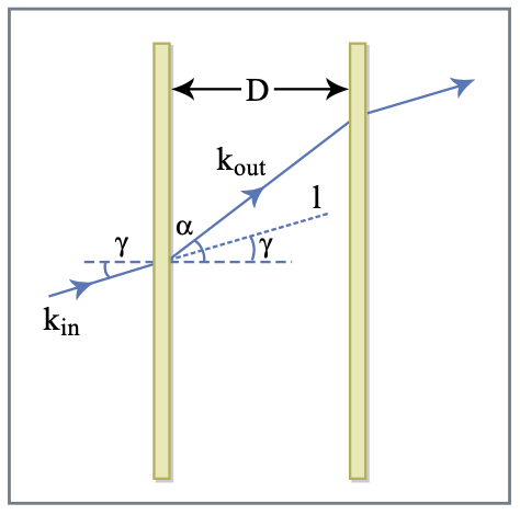
The first element scatters the input beam with wave vector \(\text{k}_{in}\) and input path vector \(\text{l}\) into the direction \(\text{k}_{out}\). The beam passes between the first and the second element and is scattered back into its original direction. The phase difference by the scattered beam and the reference beam without the grating is: \(\phi (\omega) = \text{k}_{out} (\omega) \cdot \text{l}\). Considering free-space propagation between the two elements, we have \(|\text{k}_{out}| = \omega/c\), and the accumulated phase can be written as
\[\phi (\omega) = \dfrac{\omega}{c} |\text{l}| \cos [\gamma - \alpha (\omega)] = \dfrac{\omega}{c} \dfrac{D}{\cos (\gamma)} \cos [\gamma -\alpha (\omega)]\label{eq3.7.6} \]
where: \(\gamma\) is the angle between the incident wave vector and the normal to the first element; \(\alpha\) is the angle of the outgoing wave vector, which is a function of frequency; \(D\) is the spacing between the scattering elements along a direction parallel to their normal. In the case of a grating pair the frequency dependence of the diffraction angle \(α\) is governed by the grating law, that in the case of first-order diffraction is given by:
\[\dfrac{2\pi c}{omega} = d[\sin \alpha (\omega) - \sin \gamma]\label{eq3.7.7} \]
where \(d\) is the groove spacing of the grating. Using Eq.(\(\ref{eq3.7.6}\)) and Eq.(\(\ref{eq3.7.7}\)), it is possible to obtain analytic expressions for the GDD and the higher-order dispersion terms (for single pass):
\[\phi '' (\omega) = -\dfrac{4\pi^2 cD}{\omega^3 d^2 \cos^3 \alpha (\omega)}\label{eq3.7.8} \]
\[\phi ''' (\omega) = \dfrac{12 \pi^2 cD}{\omega^4 d^2 \cos^3 \alpha (\omega)} \left (1 + \dfrac{2 \pi c \sin \alpha (\omega)}{\omega d \cos^2 \alpha (\omega)} \right ) \nonumber \]
It is evident from Eq.(\(\ref{eq3.7.8}\)) that grating pairs give negative dispersion. \(D\) is the distance between the gratings. A disadvantage of the grating pair is the diffraction loss. For a double-pass configuration the loss is typically 75%. Also the bandwidth for efficient diffraction is limited.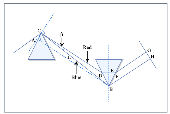
Figure 3.16: Prism pair for dispersion compensation. The blue wavelengths have less material in the light path then the red wavelengths. Therefore, blue wavelengths are less delayed than red wavelength Figure by MIT OCW.
In the case of a Brewster-angled prism pair Eq.(\(\ref{eq3.7.6}\)) reduces to the following expression (for single pass) [56]:
\[\phi (\omega) = \dfrac{\omega}{c} \ell_p \cos \beta (\omega) \nonumber \]
where \(\ell_p\) is the distance between prism apices and \(\beta (\omega)\) is the angle between the refracted ray at frequency \(\omega\) and the line joining the two apices. The second and third order dispersion can be expressed in terms of the optical path \(P(\lambda) = \ell_p \cos \beta (\lambda)\):
\[\phi '' (\omega) = \dfrac{\lambda^3}{2\pi c^2} \dfrac{d^2 P}{d\lambda^2} \nonumber \]
\[\phi ''' (\omega) = - \dfrac{\lambda^4}{4 \pi^2 c^3} \left ( 3 \dfrac{d^2 P}{d \lambda^2} + \lambda \dfrac{d^3 P}{d \lambda^3} \right ) \nonumber \]
with the following derivatives of the optical path with respect to wavelength evaluated at Brewster’s angle:
\[\dfrac{d^2 P}{d\lambda^2} = 2[n'' + (2n - n^{-3})(n')^2] \ell_p \sin \beta - 4(n')^2 \ell_p \cos \beta \nonumber \]
\[\dfrac{d^3 P}{d \lambda^3} = [6(n')^3 (n^{-6} + n^{-4} - 2n^{-2} + 4n^2) + 12n'n''(2n - n^{-3}) + \nonumber \]
\[+ 2n'''] \ell_p \sin \beta + 12[(n^{-3} -2n)(n')^3 - n'n''] \ell_p \cos \beta \nonumber \]
where \(n\) is the refractive index of the prism material; \(n'\), \(n''\) and \(n'''\) are respectively, the first-, second- and third-order derivatives of \(n\), with respect to wavelength. The prism-compressor has the advantage of reduced losses. Using only fused silica prisms for dispersion compensation, sub-10-fs light pulses have been generated directly from an oscillator in 1994 [79]. In 1996, pulses with tens of microjoules energy, spectrally broadened in a gas-filled hollow fiber were compressed down to 10 fs using a prism compressor [48]. Both in the case of grating and prism pairs, negative GDD is associated with a significant amount of higher-order dispersion, which cannot be lowered or adjusted independently of the desired GDD, thus limiting the bandwidth over which correct dispersion control can be obtained. This drawback has been only partially overcome by combining prism and grating pairs with third-order dispersion of opposite sign. In this way pulses as short as 6 fs have been generated in 1987 [46], and less than 5 fs in 1997 [47], by external compression. This combination cannot be used for few-optical-cycle pulse generation either in laser oscillators, due to the high diffraction losses of the gratings, or in external compressors at high power level, due to the onset of unwanted nonlinearities in the prisms.
Dispersion Compensating Mirrors
Chirped mirrors are used for the compression of high energy pulses, because they provide high dispersion with little material in the beam path, thus avoiding nonlinear effects in the compressor.
Grating and prism compressors suffer from higher order dispersion. In 1993 Robert Szipoecs and Ferenc Krausz [80] came up with a new idea, so called chirped mirrors. Laser mirrors are dielectric mirrors composed of alternating high and low index quarter wavelength thick layers resulting in strong Bragg-reflection. In chirped mirrors the Bragg wavelength is chirped so that different wavelength penetrate different depth into the mirror upon reflection giving rise to a wavelength dependent group delay. It turns out that the generation of few-cycle pulses via external compression [95] as well as direct generation from Kerr lens mode-locked lasers [58] relies heavily on the existence of chirped mirrors [57, 83, 59] for dispersion compensation. There are two reasons to employ chirped mirrors . First the high-reflectivity bandwidth, \(\Delta f\), of a standard dielectric Bragg-mirror is determined by the Fresnel reflectivity \(r_B\) of the high, \(n_H\), and low, \(n_L\), index materials used for the dielectric mirror
\[r_B = \dfrac{\Delta f}{f_c} = \dfrac{n_H - n_L}{n_H + n_L} \nonumber \]
where \(f_c\) is again the center frequency of the mirror. Metal mirrors are in general too lossy, especially when used as intracavity laser mirrors. For material systems typically used for broadband optical coatings such as Silicon Dioxide and Titanium Dioxide with \(n_{\ce{SiO2}} = 1.48\) and \(n_{\ce{TiO2}} = 2.4\), (these indexes might vary depending on the deposition technique used), a fractional bandwidth \(\Delta f/f_c = 0.23\) can be covered. This fractional bandwidth is only about a third of an octave spanning mirror \(\Delta f/f_c = 2/3\). Furthermore, the variation in group delay of a Bragg-mirror impacts already pulses that fill half the spectral range \(\Delta f = 0.23f_c\). A way out of this dilemma was found by introducing chirped mirrors [57], the equivalent of chirped fiber Bragg gratings, which at that time were already well developed components in fiber optics [60]. When the Bragg wavelength of the mirror stack is varied slowly enough and no limitation on the number of layer pairs exists, an arbitrary high reflectivity range of the mirror can be engineered. The second reason for using chirped mirrors is based on their dispersive properties due to the wavelength dependent penetration depth of the light reflected from different positions inside the chirped multilayer structure. Mirrors are filters, and in the design of any filter, the control of group delay and group delay dispersion is difficult. This problem is further increased when the design has to operate over wavelength ranges up to an octave or more.
matching problem
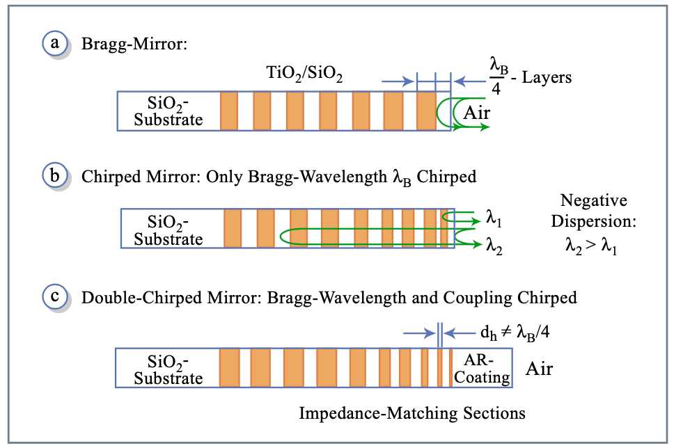
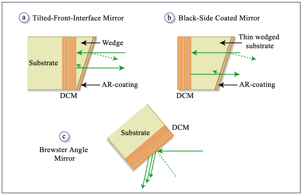
Several designs for ultra broadband dispersion compensating mirrors have been developed over the last years. For dispersion compensating mirrors which do not extend the high reflectivity range far beyond what a Bragg-mirror employing the same materials can already achieve, a multi-cavity filter design can be used to approximate the desired phase and amplitude properties [61, 62]. For dispersion compensating mirrors covering a high reflectivity range of up to \(\Delta f/f_c = 0.4\) the concept of double-chirped mirrors (DCMs) has been developed [83][81]. It is based on the following observations. A simple chirped mirror provides high-reflectivity over an arbitrary wavelength range and, within certain limits, a custom designable average group delay via its wavelength dependent penetration depth [73] (see Figure 3.17 (a) and (b) ). However, the group delay as a function of frequency shows periodic variations due to the impedance mismatch between the ambient medium and the mirror stack, as well as within the stack (see Figure 3.17 b and Figure 3.18). A structure that mitigates these mismatches and gives better control of the group delay dispersion (GDD) is the double-chirped mirror (DCM) (Figure 3.17 c), in a way similar to that of an apodized fiber Bragg grating [64].
Kaertner, F. X., et al. "Design and fabrication of double-chirped mirrors." Optics Letters 15 (1990): 326-328.
Figure 3.18: Comparison of the reflectivity and group delay of chirped mirrors with 25 layer pairs and refractive indices \(n_H = 2.5\), and \(n_L = 1.5\). The upper portion shows the enlarged top one percent of the reflectivity. The dotted curves show the result for a simple chirped mirror. The dashed and solid curves show the result for double-chirped mirrors where in addition to the chirp in the Bragg wave number \(k_B\) the thickness of the high-index layers is also chirped over the first 12 layer pairs from zero to its maximum value for a linear chirp, i.e. \(\alpha = 1\), (dashed curves) and for a quadratic chirp, i.e. \(\alpha = 2\) (solid curves). [83].
Figure 3.18 shows the reflectivity and group delay of several Bragg and chirped mirrors composed of 25 index steps, with \(n_H = 2.5\) and \(n_L = 1.5\), similar to the refractive indices of \(\ce{TiO2}\) and \(\ce{SiO2}\), which result in a Fresnel reflectivity of \(r_B = 0.25\). The Bragg-mirror can be decomposed in symmetric index steps [83]. The Bragg wavenumber is defined as \(k_B = \pi/(n_Ld_L + n_H d_H)\), where \(d_L\) and \(d_H\) are the thicknesses of the low and high index layer, respectively. The Bragg wavenumber describes the center wavenumber of a Bragg mirror composed of equal index steps. In the first case, (Figure 3.18, dash-dotted line) only the Bragg wave number is linearly chirped from \(6.8 \mu m^{-1} < k_B < 11 \mu m^{-1}\) over the first 20 index steps and held constant over the last 5 index steps. The reflectivity of the structure is computed assuming the structure imbedded in the low index medium. The large oscillations in the group delay are caused by the different impedances of the chirped grating and the surrounding low index material causing a strong reflection at the interface of the low index material and the grating stack. By adiabatic matching of the grating impedance to the low index material this reflection can be avoided. This is demonstrated in Figure 3.18 by the dashed and solid curves, corresponding to an additional chirping of the high index layer over the first 12 steps according to the law \(d_H = (m/12)^{\alpha} \lambda_{B,12}/(4n_H)\) with \(\alpha = 1\), and 2, for linear and quadratic adiabatic matching. The argument m denotes the m-th index step and \(\lambda_{B,12} = 0.740\mu m\). The strong reduction of the oscillations in the group delay by the double-chirp technique is clearly visible. Quadratic tapering of the high index layer, and therefore, of the grating already eliminates the oscillations in the group delay completely, which can also be shown analytically by coupled mode analysis [81]. Because of the double chirp a high transmission window at the short wavelength end of the mirror opens up which is ideally suited for the pumping of Ti:sapphire lasers. So far, the double-chirped mirror is only matched to the low index material of the mirror. Ideally, the matching can be extended to any other ambient medium by a properly designed AR-coating. However, this AR-coating has to be of very high quality, i.e. very low residual reflectivity ideally a power reflectivity of \(10^{-4}\), i.e. an amplitude reflectivity of \(r = 10^{-2}\) is required. The quality of the AR-coating can be relaxed, if the residual reflection is directed out of the beam path. This is achieved in so called tilted front-side or back-side coated mirrors [65], [66], (Figure 3.19 (a) and (b)). In the back- side coated mirror the ideal DCM structure, which is matched to the low index material of the mirror is deposited on the back of a substrate made of the same or at least very similar low index material. The AR-coating is deposited on the front of the slightly wedged substrate, so that the residual reflection is directed out of the beam and does not affect the dispersion properties. Thus the task of the AR-coating is only to reduce the Fresnel losses of the mirror at the air-substrate interface, and therefore, it is good enough for some applications, if the residual reflection at this interface is of the order of 0.5%. However, the substrate has to be very thin in order to keep the overall mirror dispersion negative, typically on the order of 200-500 \(\mu\)m. Laser grade quality optics are hard to make on such thin substrates and the stress induced by the coating leads to undesired deformation of the substrates. The front-side coated mirror overcomes this shortcoming by depositing the ideal DCM-structure matched to the index of the wedge material on a regular laser grade substrate. A 100-200 μm thin wedge is bonded on top of the mirror and the AR-coating is then deposited on this wedge. This results in stable and octave spanning mirrors, which have been successfully used in external compression experiments [69]. Both structures come with limitations. First, they introduce a wedge into the beam, which leads to an undesired angular dispersion of the beam. This can partially be compensated by using these mirrors in pairs with oppositely oriented wedges. The second drawback is that it seems to be impossible to make high quality AR-coatings over one or more than one octave of bandwidth, which have less than 0.5% residual reflectivity [68], i.e. on one reflection such a mirror has at least 1% of loss, and, therefore, such mirrors cause high losses inside a laser. For external compression these losses are acceptable. A third possibility for overcoming the AR-coating problem is given by using the ideal DCM under Brewster-angle incidence, (Figure 3.19) [67]. In that case, the low index layer is automatically matched to the ambient air. However, under p-polarized incidence the index contrast or Fresnel reflectivity of a layer pair is reduced and more layer pairs are necessary to achieve high reflectivity. Also the penetration depth into the mirror increased, so that scattering and other losses in the layers become more pronounced. On the other hand, such a mirror can generate more dispersion per bounce due to the higher penetration depth. For external compression such mirrors might have advantages because they can cover bandwidths much wider than one octave. This concept is difficult to apply to the fabrication of curved mirrors. There is also a spatial chirp of the reflected beam, which may become sizeable for large penetration depth and has to be removed by back reflection or an additional bounce on another Brewster-angle mirror, that recombines the beam. For intracavity mirrors a way out of this dilemma is found by mirror pairs, which cancel the spurious reflections due to an imperfect AR-coating and matching structure in the chirped mirror [76]. Also this design has its drawbacks and limitations. It requires a high precision in fabrication and depending on the bandwidth of the mirrors it may be only possible to use them for a restricted range of angles of incidence.
Double-chirped mirror pairs
There have been several proposals to increase the bandwidth of laser mirrors by mutual compensation of GDD oscillations [70, 71, 72] using computer optimization. These early investigations resulted in a rather low reflectivity of less than 95% over almost half of the bandwidth considered. The ideas leading to the DCMs help us to show analytically that a design of DCM- pairs covering one octave of bandwidth, i.e. 600 nm to 1200 nm, with high reflectivity and improved dispersion characteristics is indeed possible [76]. Use of these mirror pairs in a Ti:sapphire laser system resulted in 5 fs pulses with octave spanning spectra directly from the laser [58]. Yet, the potential of these pairs is by no means fully exploited.
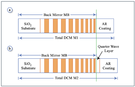
A DCM-Pair, see Figure 3.20, consists of a mirror M1 and M2. Each is composed of an AR-coating and a low-index matched double-chirped back- mirror MB with given wavelength dependent penetration depth. The high reflectivity range of the back-mirror can be easily extended to one octave by simply chirping slowly enough and using a sufficient number of layer pairs.
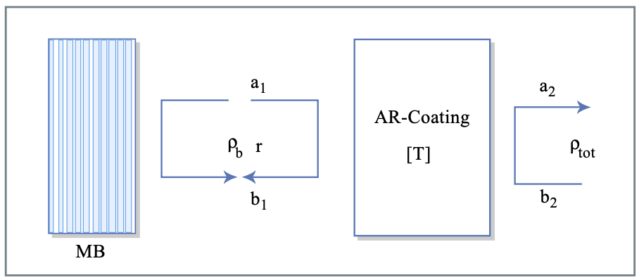
However, the smoothness of the resulting GDD strongly depends on the qual- ity of matching provided by the AR-coating and the double-chirped section. Figure 3.21 indicates the influence of the AR-coating on the GDD of the total DCM-structure. The AR-coating is represented as a two - port with two in- coming waves a1, b2 and two outgoing waves a2, b1. The connection between the waves at the left port and the right port is described by the transfer matrix
\[\left (\begin{matrix} a_1 \\ b_1 \end{matrix} \right ) = T_{ar} \left (\begin{matrix} a_2 \\ b_2 \end{matrix} \right ) \text{ with } T_{ar} = \left (\begin{matrix} \tfrac{1}{t} & \tfrac{r^*}{t^*} \\ \tfrac{r}{t} & \tfrac{1}{t^*} \end{matrix} \right )\label{eq3.7.17} \]
where we assumed that the multilayer AR-coating is lossless. Here, \(r\) and \(t\) are the complex coefficients for reflection and transmission at port 1 assuming reflection free termination of port 2. The back-mirror MB, is assumed to be perfectly matched to the first layer in the AR-coating, has full reflection over the total bandwidth under consideration. Thus its complex reflectivity in the range of interest is given by
\[\rho_b = e^{j \phi_b (\omega)}\label{eq3.7.18} \]
The phase \(\phi_b (\omega)\) is determined by the desired group delay dispersion
\[GDD_b = -d^2 \phi_b (\omega) /d\omega^2 \nonumber \]
up to an undetermined constant phase and group delay at the center frequency of the mirror, \(\omega_c\). All higher order derivatives of the phase are determined by the desired dispersion of the mirror. Analytic formulas for the design of DCMs, showing custom designed dispersion properties without considering the matching problem to the ambient air, can be found in [73]. The resulting total mirror reflectivity including the AR-coating follows from (\(\ref{eq3.7.17}\))
\[\rho_{tot} = \dfrac{t}{t^*} \rho_b \dfrac{1 - r^*/\rho_b}{1 - r \rho_b} \nonumber \]
For the special case of a perfectly reflecting back-mirror according to Equation (\(\ref{eq3.7.18}\)) we obtain
\[\rho_{tot} = \dfrac{t}{t^*} e^{j\phi_b (\omega)} \dfrac{1 - z^*}{1-z}, \text{ with } z = re^{j\phi_b (\omega)} \nonumber \]
The new reflectivity is again unity but new contributions in the phase of the resulting reflectivity appear due to the imperfect transmission properties of the AR-coating. With the transmission coefficient of the AR-coating
\[t = |t| e^{j \phi_t}, \nonumber \]
The total phase of the reflection coefficient becomes
\[\phi_{tot} = 2\phi_t + \phi_b (\omega) + \phi_{GTI} \nonumber \]
with
\[\phi_{GTI} = 2 \arctan \left [ \dfrac{Im \{z\}}{1 + Re \{z\}}\right ] \nonumber \]
Here, \(\phi_t\) is the phase of the transmission coefficient and \(\phi_{GTI}\) is the phase due to the Gire-Tournois interferometer created by the non-perfect AR-coating, i.e. \(r \ne 0\), and the back-mirror MB, (Figure 3.21). The phase \(\phi_t\) of a good AR-coating, i.e. \(|r| < 0.1\), is linear and, therefore, does not introduce undesired oscillations into the GD and GDD. However, the phase \(\phi_{GTI}\) is rapidly varying since \(\phi_b (\omega)\) varies over several \(2\pi\) over the frequency range of interest due to the monotonic group delay of the back-mirror. The size of these oscillations scale with the quality of the AR-coating, i.e. with \(|r|\). Thus, the GDD oscillations are reduced with smaller residual reflectivity of the AR-coating. Assuming, that the reflectivity \(r\) is real and smaller or equal to 0.1, the oscillations in the group delay and group delay dispersion are easily estimated by
\[T_{g, GTI} = \dfrac{d\phi_{GTI}}{d\omega} \approx -r T_{gb} (\omega) \cos [\phi_b (\omega)] \nonumber \]
with
\[\begin{array} {rcl} {T_{gb} (\omega)} & = & {-d\phi_b (\omega)/d\omega,} \\ {GDD_{GTI}} & = & {\tfrac{d^2\phi_{GTI}}{d\omega^2}} \\ {} & \approx & {r(T_{gb}^2 (\omega) \sin [\phi_b (\oemga)] - GDD_b \cos [\phi_b (\omega)])} \end{array} \nonumber \]
The GTI-reflections add up coherently when multiple reflections on chirped mirrors occur inside the laser over one round-trip, leading to pre- and post pulses if the mode-locking mechanism is not strong enough to suppress them sufficiently. Experimental results indicate that a residual reflection in the AR-coating of \(r < 0.01\) and smaller, depending on the number of reflections per round-trip, is required so that the pre- and post pulses are sufficiently suppressed. This corresponds to an AR-coating with less than \(10^{-4}\) residual power reflectivity, which can only be achieved over a very limited range, as discussed above.
Over a limited wavelength range of 350 nm centered around 800 nm low residual power reflectivities as small as \(10^{-4}\) have been achieved effectively after reoptimization of the AR-coating section and the double-chirped section to form a combined matching section of higher matching quality. For even larger bandwidth, approaching an octave, a residual power reflectivity of \(10^{-4}\) is no longer possible [68]. A way out of this limitation is offered by the observation, that a coherent subtraction of the pre- and post-pulses to first order in \(r\) is possible by reflections on a mirror pair M1 and M2, see Figure 3.20 (a) and (b). A series of two reflections on a mirror with reflectivity (3.97) and on a similar mirror with an additional phase shift of \(\pi\) between the AR-coating and the back-mirror, having a reflectivity (3.97) where \(z\) is replaced by \(-z\), leads to a coherent subtraction of the first order GTI-effects. The resulting total reflectivity of the two reflections is given by the product of the individual complex reflectivities assuming the same AR-coating
\[\rho_{tot,2} = -\left (\dfrac{t}{t^*} \right )^2 e^{i2\phi_b (\omega)} \dfrac{1 - z^*^2}{1 - z^2} \nonumber \]
Now, the GTI-effects scale like the power reflectivity of the AR-coating \(r^2\) instead of the amplitude reflectivity \(r\), which constitutes a tremendous improvement, since it is possible to design AR-coatings to the low index material Si02 of the mirror with a residual power reflectivity between 0.001 and 0.01 while covering one octave of bandwidth [68]. However, there does not exist a single physical layer which generates a phase shift of \(\pi/2\) during one passage for all frequency components contained in an octave. Still, a layer with a quarter wave thickness at the center frequency is a good starting design. Then the back-mirror MB in the Mirror M2 can be reoptimized to take care of the deviation from a quarter wave thickness further away from the center frequency, because the back-mirror acts as a highly dispersive medium where the phase or group delay can be designed at will.
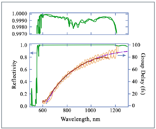
Figure 3.23 shows in the top graph the designed reflectivity of both mirrors of the pair in high resolution taking into account the absorption in the layers. The graph below shows the reflectivity of the mirror, which has in addition high transmission between 510-550 nm for pumping of the Ti:sapphire crystal. Each mirror consists of 40 layer pairs of \(\ce{SiO2}\) and \(\ce{TiO2}\) fabricated using ion-beam sputtering [74, 75]. Both mirror reflectivities cover more than one octave of bandwidth from 580 nm to 1200 nm or 250 to 517 THz, with an average reflectivity of about 99.9% including the absorption in the layers. In addition, the mirror dispersion corrects for the second and higher order dispersion of all intracavity elements such as the Ti:sapphire crystal and the thin, small angle, \(\ce{BaF2}\) wedges, for fine adjustment of the dispersion from 650 nm to 1200 nm within the 12 bounces occurring in one roundtrip. The choice for the lower wavelength boundary in dispersion compensation is determined and limited by the pump window of Ti:sapphire. The dispersion measurement was performed using white light interferometry [77], up to about 1100 nm because of the silicon detector roll-off. The oscillations in the group delay of each mirror are about 10 times larger than those of high quality DCMs covering 350 nm of bandwidth [?]. However, in the average group delay of both mirrors the oscillations are ideally suppressed due to cancellation by more than a factor of ten. Therefore, the effective residual reflectivity of the mirror pair covering one octave, \(r^2\), is even smaller than that of conventional DCMs.
Methods for active dispersion compensation
Various schemes for active pulse compression have been developed based on the use of liquid-crystal modulators (LCM), acousto-optic modulators (AOM), and mechanically deformable mirrors.
Dispersion compensation using liquid crystal modulators
A pulse shaping technique [84] based on the use of a LCM for pulse compression offers the advantage of a large bandwidth (300-1500 nm) and in situ adaptive phase control, see Figure3.23. In 1997 Yelin \(et\ al\). [85] demonstrated an adaptive method for femtosecond pulse compression based on LCM. Strongly chirped 80-fs pulses generated by an oscillator were sent in a 4-\(f\) pulse shaper composed of a pair of thin holographic transmission gratings. A programmable one-dimensional LCM, placed in the Fourier plane of the shaper, was used as an updatable filter for pulse spectral manipulation. Pulses as short as 11 fs (transform-limited duration: 9 fs) have been obtained, employing an optimization algorithm for adaptive compression based on a search in the two-dimensional space of second- and third-order dispersion coefficients. In 2001, Karasawa et al. [86] demonstrated pulse compression, down to 5 fs, of broadband pulses from an argon-filled hollow fiber, using only a LCM for phase compensation. More recently [51], pulses as short as 3.8 fs have been achieved through a closed-loop combination of a liquid-crystal spatial light modulator for adaptive pulse compression and spectral-phase interferometry for direct electric-field reconstruction (SPIDER) [87] measurements as feedback signal.
One problem of the method is pixelization in the Fourier plane owing to the technology of the liquid-crystal active matrix. Diffraction on pixel edges and absorption by the black matrix introduce parasitic effects. The requirement that the actual spectral modulation should approximate a smooth function despite the fixed, finite size of the individual modulator elements, limits the temporal range over which pulse compression can be achieved [88]. Other problems are related to the optical damage of the LCM, which limits the maximum pulse energy, and to the high losses introduced by the device.
Various nonpixelated devices have been proposed: Dorrer \(et\ al\). have reported on an optically addressed LCM (liquid crystal light valve) [89]. The light valve consists of two continuous transparent electrodes and continuous layers of a nematic twisted liquid crystal and of photoconductive \(\ce{Bi12SiO20}\) (BSO). A local variation of illumination of the BSO layer (in the blue green spectral region) induces a change in conductivity. When a voltage is applied between the two electrodes, the variation of the BSO conductivity results in a change in the voltage drop across the liquid crystal layer. As the birefringence of the liquid crystal is voltage dependent, a local variation of the refractive index is created, which translates into a variation of the optical phase of the local spectral component. The light valve is addressed by using a display device. Pixelation effects are avoided because the light valve itself is a continuous device. The control of the light valve is more complicated than for the electrically addressed LCM. Moreover, due to its limited spatial frequency response, the spectral resolution is limited.
Dispersion compensation using acousto-optic modulators
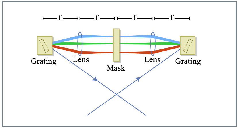
In 1997 Tournois proposed an acousto-optic programmable dispersive filter (AOPDF), to provide large dispersion-compensation ranges[91]. The device is based on a collinear acousto-optic interaction in a birefringent uniaxial crystal, see Figure 3.24. The acoustic frequency is a variable function of time and provides control over the group delay of the diffracted optical pulse. At the same time, the spectral amplitude of the diffracted pulse is driven by the intensity of the acoustic signal. As demonstrated in Ref. [91], the optical output \(E_{out}(t)\) of the AOPDF is proportional to the convolution of the optical input, \(E_{in}(t)\), and the scaled acoustic signal:
\[E_{out} (t) \propto E_{in} (t) otimes S(t/\alpha) \nonumber \]
where the scaling factor \(\alpha = \Delta n(V/c)\) is the ratio of the speed of sound to the speed of light times the index difference between the ordinary and the extraordinary waves. Therefore, by generating the proper function \(S(t)\), it is possible to generate any arbitrary convolution with a temporal resolution given by the inverse of the filter bandwidth. Such device have been used in kilohertz chirped-pulse amplification laser chains compensating for gain narrowing and residual phase errors with the AOPDF, resulting in the generation of 17-fs transform-limited pulses [92]. The total throughput is 10- 50%, depending on the bandwidth of the device. Devices approaching one octave in bandwidth are possible.
Figure 3.24: Acousto-optic programable pulse shaper. One element can shape amplitude and phase of the pulse.
Dispersion compensation using deformable mirrors
Mechanically deformable mirrors can be used for active dispersion control, as proposed by Heritage \(et\ al\). [93]. More recently, pulse compression has been achieved using an electrostatically deformable, gold-coated, silicon nitride membrane mirror, placed in the Fourier plane of a \(4f\) zero-dispersion stretcher [94]. The membrane was suspended over an array of 39 actuator electrodes. The potential applied to each actuator generates an electrostatic attraction between the membrane and the electrode, thus inducing a deformation of the mirror surface, which translates into a modulation of the phase of the spectral components of the input pulse. The total phase difference is \(\phi = 2(2\pi)\Delta z/\lambda\), where \(\Delta z\) is the deflection of the mirror. The minimum radius of curvature of the mirror membrane is given by \(R = T/P\), where \(T\) is the membrane tension and \(P\) is the maximum electrostatic pressure. This limitation of the membrane curvature restricts the possibility of the mirror correction of higher-order phases. The main advantages of this method are the following: the phase modulation is smoothly varying; reduced losses due to the high reflectivity (97%) of the mirror; relatively high actuator density. Experiments have been performed with a mode-locked Ti:sapphire laser, where the deformable mirror recompressed a 15 fs pulse, previously stretched to 90 fs by dispersion in glass, back to approximately the bandwidth limit [94].
Recently, dispersion control over a bandwidth of ~ 220 THz has been demonstrated by A. Baltuška et al. [95] using a compressor consisting of a pair of chirped mirrors and a grating dispersion line with a computer-controlled flexible mirror positioned in the focal plane. The total throughput of the pulse shaper was less than 12% because of the low diffraction efficiency of the grating. Using this compressor, the visible-near-IR pulses, generated by optical parametric amplification, were compressed to a 4-fs duration.
Hollow Fiber Compression Technique
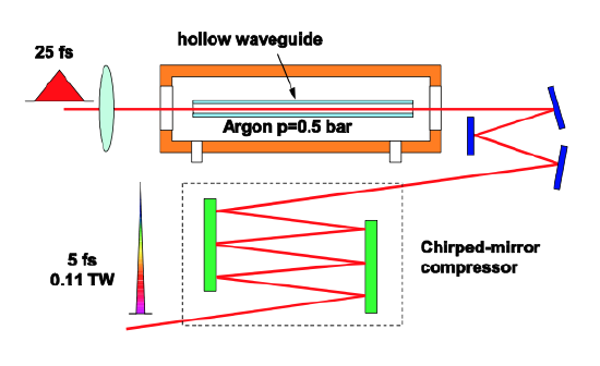
Single mode fiber only allows compression of low energy pulses. In 1996 the group of DeSilvestri in Milan [48] developed a technique that enables the generation of few-cycle light pulses with energies in the millijoule range. The technique is based on propagation of laser pulses in a hollow fiber filled with noble gases (hollow fiber compression technique), see Figure 3.25.The modes of the hollow fiber are leaky modes, i.e. they experience radiation loss. However, there is one mode, the EH\(_{11}\) mode, which has considerably less loss than the higher order modes. This mode is used for pulse compression. The nonlinear index in the fiber can be controlled with the gas pressure. Typical fiber diameters are 100-500 μm and typical gas pressures are in the range of 0.1-3bar. As in the case of fiber compression it is important to consider the optimization of nonlinear interaction and dispersion. Both the medium and waveguide dispersion has to be taken into account. For more detail see ref. [107].
For the time being, the hollow fiber compression technique is the only way to generate sub-10fs millijoule pulses. This will change soon with the advent of parametric chirped pulse amplification.