
7.2: Additive Pulse Mode Locking
- Page ID
- 44666

Like Kerr-Lens Mode Locking also Additive Pulse Mode Locking (APM) is an artificial saturable absorber effect [17][18][19][20][21][22]. Figure 7.17 shows the general principle at work. A small fraction of the light emitted from the main laser cavity is injected externally into a nonlinear fiber. In the fiber strong SPM occurs and introduces a significant phase shift between the peak and the wings of the pulse. In the case shown the phase shift is \(\pi\).
A part of the modified and heavily distorted pulse is reinjected into the cavity in an interferometrically stable way, such that the injected pulse interferes constructively with the next cavity pulse in the center and destructively in the wings. This superposition leads to a shorter intracavity pulse and the pulse shaping generated by this process is identical to the one obtained from a fast saturable absorber. Again, an artificial saturable absorber action is generated.
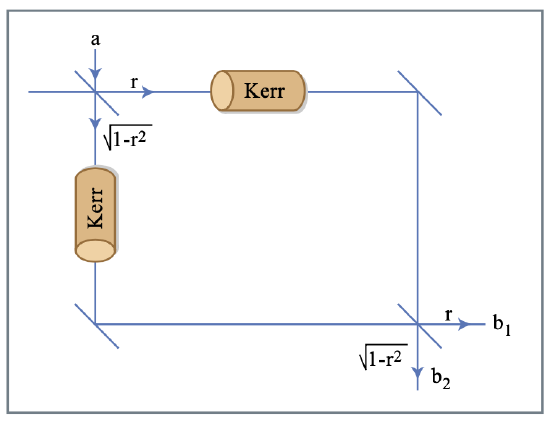
Figure by MIT OCW.
Figure 7.18 shows a simple nonlinear interferometer. In practice, such an interferometer can be realized in a self-stabilized way by the use of both polarizations in an isotropic Kerr medium with polarizer and analyzer as shown in Figure 7.19.
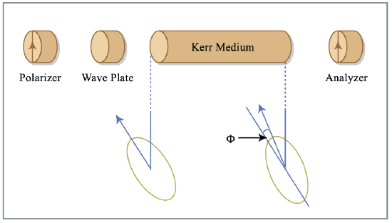
Figure by MIT OCW.
The Kerr effect rotates the polarization ellipse and thus transforms phase modulation into amplitude modulation. The operation is in one-to-one correspondence with that of the nonlinear Mach-Zehnder interferometer of Fig.7.18. The system of Figure 7.18 can be analyzed rather simply and thus it is worthwhile to look at the derivation and the implicit assumptions. The couplers are described by the scattering matrices
\[S = \begin{bmatrix} r & \sqrt{1 - r^2} \\ \sqrt{1 - r^2} & - r \end{bmatrix}. \nonumber \]
The outputs of the interferometer are then
\[b_1 = [r^2 e^{-j \phi_1} + (1 - r^2) e^{-j \phi_2} ] a, \nonumber \]
\[b_2 = 2r \sqrt{1 - r^2} \exp \left [ - j \dfrac{\phi_1 + \phi_2}{2} \right ] \sin \left [ \dfrac{\phi_2 - \phi_1}{2} \right ] a, \nonumber \]
\(\phi_1\) and \(\phi_2\) are the phase shifts in the two arms composed of both linear "bias" contributions \(\phi_{bi}\) and the Kerr phase shifts \(\phi_{Ki}\)
\[\phi_i = \phi_{bi} + \phi_{Ki}, (i = 1, 2), \nonumber \]
\[\phi_{Ki} = \kappa_i |a|^2, (i = 1,2). \nonumber \]
The power in output port two is related to the linear and nonlinear losses
\[\begin{array} {rcl} {|b_2|^2} & = & {2r^2 (1 - r^2) (1 - \cos [\phi_2 - \phi_1])|a|^2} \\ {} & = & {2r^2 ( 1 - r^2) \{(1 - \cos [\phi_{b2} - \phi_{b1}]) + \sin [\phi_{b2} - \phi_{b1}] (\phi_{K2} - \phi_{K1}) \} |a|^2} \end{array} \nonumber \]
Depending on the bias phase \(\phi_b = \phi_{b2} - \phi_{b1}\), the amplitude loss is
\[l = r^2 (1 - r^2) (1 - \cos \phi_b) |a|^2,\label{eq7.2.7} \]
and the \(\gamma\)−parameter of the equivalent fast saturable absorber is
\[\gamma = (\kappa_1 - \kappa_2)r^2 (1 - r^2) \sin \phi_b.\label{eq7.2.8} \]
If the interferometer forms part of a resonant system, the frequency of the system is affected by the phase shift of the interferometer and in turn affects the phase.
When the resonant frequencies of the linear system (\(\gamma = \delta = 0\)) without the interferometer should remain the resonant frequencies with the interferometer, the net phase shift of the interferometer has to be chosen to be zero. Since a small loss has been assumed and hence \(r^2 \gg 1 - r^2\)
\[\text{Im } [r^2 e^{-j \phi_{b1}} + (1 - r^2) e^{-j \phi_{b2}}] = \text{Im } [r^2 (1 - j \phi_{b1}) + (1 - r^2) e^{-j \phi_{b2}}] = 0 \nonumber \]
or
\[\phi_{b1} = \dfrac{-(1 - r^2)}{r^2} \sin \phi_{b2}. \nonumber \]
and \(\cos \phi_{b1} = 1\). With this adjustment, the response of the interferometer becomes
\[\begin{array} {rcl} {b_1} & \approx & {a + \Delta a = a - (1 - r^2)(1 - \cos \phi) a} \\ {} & \ & {-(1 - r^2)(\phi_{K2} - \phi_{K1}) \sin \phi a} \\ {} & \ & {-j r^2 \phi_{K1} - j (1 - r^2) \phi_{K2} \cos \phi a,} \end{array} \nonumber \]
where we have set \(\phi = \phi_{b2}\). This gives for the parameters of the master equation \(l, \gamma\) and \(\delta\)
\[l = (1 - r^2) (1 - \cos \phi), \nonumber \]
\[\gamma = (\kappa_1 - \kappa_2)(1 - r^2) \sin \phi, \nonumber \]
\[\delta = \kappa_1 r^2 + \kappa_2 (1 - r^2) \cos \phi. \nonumber \]
Due to the special choice of the bias phase there is no contribution of the nonlinear interferometer to the linear phase. This agrees with expressions (\(\ref{eq7.2.7}\)) and (\(\ref{eq7.2.8}\)). The Kerr coefficients are
\[\kappa_1 = r^2 \left (\dfrac{2\pi}{\lambda} \right ) \dfrac{n_2}{A_{eff}} L_{kerr}, \nonumber \]
\[\kappa_2 = (1 - r^2) \left (\dfrac{2\pi}{\lambda} \right ) \dfrac{n_2}{A_{eff}} L_{kerr}. \nonumber \]
Here, \(\lambda\) is the free space wavelength of the optical field, \(A_{eff}\) is the effective area of the mode, \(n_2\) the intensity dependent refractive index, and \(L_{Kerr}\) is the length of the Kerr medium. Figure 7.20 is the saturable absorber coefficient \(\gamma\) normalized to the loss and Kerr effect (note that \(\gamma\) goes to zero when the loss goes to zero) as a function of \(r^2\)
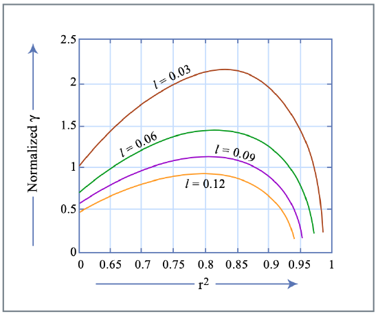
Figure by MIT OCW.
Large saturable absorber coefficients can be achieved at moderate loss values.
Bibliography
[1] D. E. Spence, P. N. Kean, W. Sibbett, ”60-fsec pulse generation from a self-mode-locked Ti:Sapphire laser”, Opt. Lett. 16, pp. 42 — 44 (1991)
[2] U. Keller, G. W ’tHooft, W. H. Knox, J. E. Cunningham, ”Femtosec- ond Pulses from a Continuously Self-Starting Passively Mode-Locked Ti:Sapphire Laser,” Opt. Lett. 16, pp.1022 — 1024 (1991).
[3] D. K. Negus, L. Spinelli, N. Goldblatt, G. Feugnet, ”Sub-100 femtosec- ond pulse generation by Kerr lens modelocking in Ti:Sapphire,” in Ad- vanced Solid-State Lasers, G. Dube, L. Chase, Eds. (Optical Society of America, Washington, D.C., 1991), 10, pp.120 — 124.
[4] F. Salin, J. Squier and M. Piche, ”Mode locking of Ti:Al2O3 lasers and self-focusing: a Gaussian approximation,” Opt. Lett. 16, pp. 1674 — 1676 (1991).
[5] M. Piche, F. Salin, ”Self-mode locking of solid-state lasers without aper- tures”, Opt. Lett. 18, pp. 1041 — 1043 (1993).
[6] G. Cerullo, S. De Silvestri, V. Magni, L. Pallaro, ”Resonators for Kerr- lens mode-locked femtosecond Ti:sapphire lasers”, Opt. Lett. 19, pp. 807 — 809 (1994).
[7] G. Cerullo, S. De Silvestri, V. Magni, ”Self-starting Kerr Lens Mode- Locking of a Ti:Sapphire Laser”, Opt. Lett. 19, pp. 1040 — 1042 (1994).
[8] L. Dahlström, ”Passive modelocking and Q-switching of high power lasers by means of the optical Kerr effect,” Opt. Comm. 5, pp. 157 — 162 (1972).
[9] E. G. Lariontsev and V. N. Serkin, ”Possibility of using self-focusing for increasing contrast and narrowing of ultrashort light pulses,” Sov. J. Quant. Electron. 5, pp. 769 — 800 (1975).
[10] K. Sala, M. C. Richardson, N. R. Isenor, ”Passive modelocking of Lasers with the optical Kerr effect modulator,” IEEE J. Quant. Electron. QE- 13, pp. 915 — 924 (1977).
[11] H. Kogelnik and T. Li, ”Laser Beams and Resonators,” Appl. Opt. 5, pp. 1550 — 1566 (1966).
[12] H. Kogelnik, E. P. Ippen, A. Dienes and C. V. Shank, ”Astigmatically Compensated Cavities for CW Dye Lasers,” IEEE J. Quantum Electron. QE-8, pp. 373 — 379 (1972).
[13] O. Svelto, ”Principles of Lasers,” 3rd Edition, Plenum Press, New York and London, (1989).
[14] H. A. Haus, ”Fields and Waves in Optoelectronics”, Prentice Hall 1984.
[15] F. K. Kneubühl and M. W. Sigrist, ”Laser,” 3rd Edition, Teubner Ver- lag, Stuttgart (1991).
[16] A. E. Siegman, ”Lasers,” University Science Books, Mill Valley, Califor- nia (1986).
[17] K. J. Blow and D. Wood, ”Modelocked lasers with nonlinear external cavities,” J. Opt. Soc. Am. B 5, pp. 629 — 632 (1988).
[18] K. J. Blow and B. P. Nelson, ”Improved mode locking of an F-center laser with a nonlinear nonsoliton external cavity,” Opt. Lett. 13, pp. 1026 —1028 (1988).
[19] P. N. Kean, X. Zhu, D. W. Crust, R. S. Grant, N. Langford and W. Sibbett, ”Enhanced mode locking of color-center lasers,” Opt. Lett. 14, pp. 39 — 41 (1989).
[20] J.Mark,L.Y.Liu,K.L.Hall,H.A.HausandE.P.Ippen,”Femtosecond pulse generation in a laser with a nonlinear external resonator,” Opt. Lett. 14, pp. 48 — 50 (1989).
[21] E. P. Ippen, H. A. Haus and L. Y. Liu, ”Additive pulse mode locking,” J. Opt. Soc. Am. B 6, pp. 1736 — 1745 (1989).
[22] J. Goodberlet, J. Jacobson and J. G. Fujimoto, P. A. Schultz and T. Y. Fan, ”Self-starting additive-pulse mode-locked diode-pumped Nd:YAG laser”, Opt. Lett. 15, pp. 504 —506 (1990).
[23] F. X. Kärtner, L. R. Brovelli, D. Kopf, M. Kamp, I. Calasso and U. Keller: ”Control of Solid-State Laser Dynamics by Semiconductor De- vices, Optical Engineering, 34, pp. 2024 — 2036, (1995).
[24] K. Tamura, ”Additive-pulse limiting”, Opt. Lett. 19, pp. 31 — 33 (1994).
[25] H. A. Haus, J. G. Fujimoto and E. P. Ippen, ”Analytic Theory of Addi- tive Pulse and Kerr Lens Mode Locking,” IEEE J. Quantum Electron. 28, pp. 2086 — 2095 (1992).
[26] H. A. Haus, J. G. Fujimoto and E. P. Ippen, ”Structures of Additive Pulse Mode Locking,” J. Opt. Soc. Am. 8, pp. 2068 — 2076 (1991).