
9.4: Femtosecond Laser Frequency Combs
- Page ID
- 44677

Nevertheless, the formula (9.3.7) can be used for the control of the optical frequency comb of a femtosecond laser by controlling the cavity length and the intracavity pulse energy, via the pump power. According to Figure 9.2 every line of the optical comb determined by
\[f_m = f_{CE} + mf_R. \nonumber \]
Note, if the femtosecond laser emits a spectrum covering more than one octave, then one can frequency double part of the comb at low frequencies and beat it with the corresponding high frequency part of the comb on a photo detector, see Figure 9.5 The result is a photodector beat signal that consists of discrete lines at the beat frequencies
\[f_k = kf_R \pm f_{CE} \nonumber \]
This method for determining the carrier-envelope offset frequency is called f-to-2f interferometry.The carrier-envelope offset frequency can be extracted with filters and synchronized to a local oscillator or to a fraction of the repetition rate of the laser, for example \(f_R/4\).
Figure 9.6 shows the setup of an octave spanning 200 MHz Ti:sapphire laser where the carrier envelope offset frequency \(f_{CE}\) is locked to a local oscillator at 36 MHz using the f-to-2f self-referencing method [6]
The spectral output of this laser is shown in Figure 9.7 The spectral components at 1140 are properly delayed in a chirped mirror delay line against the spectral components at 570 nm. The 1140 nm range is frequency doubled in a 1mm BBO crystal and the frequency doubled light together with
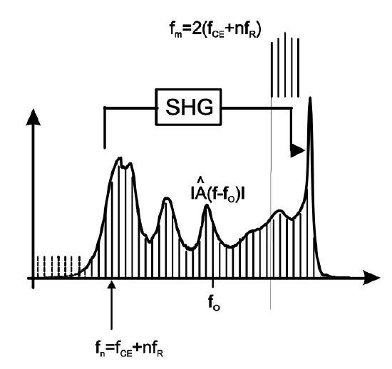
Image removed due to copyright restrictions.
Please see:
Mucke, Oliver, et al. "Self-Referenced 200 MHz Octave-Spanning Ti: Sapphire Laser with 50 Attosecond Carrier-Envelope Phase Jitter." Optics Express 13, no. 13 (June 2005): 5163-5169.
Figure 9.6: Carrier-envelope phase stabilized 200 MHz octave-spanning Ti:sapphire laser. The femtosecond laser itself is located inside the grey area. AOM, acousto-optical modulator; S, silver end mirror; OC, output coupling mirror; PBS, polarizing beam splitter cube; PMT, photomultiplier tube; PD, digital phase detector; LF, loop filter; VSA, vector signal analyzer. The carrier-envelope frequency is phase locked to 36 MHz.
Image removed due to copyright restrictions.
Please see:
Mucke, Oliver, et al. "Self-Referenced 200 MHz Octave-Spanning Ti: Sapphire Laser with 50 Attosecond Carrier-Envelope Phase Jitter." Optics Express 13, no. 13 (June 2005): 5163-5169. Used with permission.
Figure 9.7: Output spectrum of the Ti:sapphire laser on a linear (black curve) and on a logarithmic scale (grey curve). The wavelengths 570 and 1140 nm used for self-referencing are indicated by two dashed lines.
Image removed due to copyright restrictions.
Please see:
Mucke, Oliver, et al. "Self-Referenced 200 MHz Octave-Spanning Ti: Sapphire Laser with 50 Attosecond Carrier-Envelope Phase Jitter." Optics Express 13, no. 13 (June 2005): 5163-5169.
Figure 9.8: Radio-frequency power spectrum measured with a 100 kHz resolution bandwidth (RBW). The peak at the carrier-envelope frequency offset frequency exhibits a signal-to-noise ratio of ~35 dB.
the fundamental at 570 nm is projected into the same polarization via a polarizing beam splitter. The signal is then filtered through a 10nm wide filter and detected with a photomultiplier tube (PMT). A typical signal from the PMT is shown in Figure 9.8.Phase locking is achieved by a phase-locked loop (PLL) by feeding the error signal from the digital phase detector to an AOM placed in the pump beam (see Figure 9.6) which modulates the pump power and thus changes the carrier-envelope frequency via Eq.(9.82). A bandpass filter is used to select the carrier-envelope beat signal at 170 MHz. This signal is amplified, divided by 16 in frequency, and compared with a refer- ence frequency fLO supplied by a signal generator (Agilent 33250A) using a digital phase detector. The carrier-envelope beat signal is divided by 16 to enhance the locking range of the PLL. The phase detector acts as a fre- quency discriminator when the loop is open, the output is thus the difference frequency between the carrier-envelope frequency and the designated locking frequency. The output signal is amplified in the loop filter, which in our case is a proportional and integral controller, and fed back to the AOM, closing the loop. The output of the phase detector is proportional to the remaining jitter between the carrier-envelope phase evolution and the local oscillator reduced by the division ratio 16. The power spectral density (PSD) of the carrier-envelope phase fluctuations are measured with a vector signal analyzer (VSA) at the output of the phase detector. After proper rescaling by the division factor the phase error PSD is shown in Figure 9.9. The measurement was taken in steps with an equal amount of points per decade. The PSD of the carrier-envelope phase fluctuations can be integrated to obtain the total phase error. In the range above 1 MHz (see Figure 9.9), the accu- racy of this measurement is limited by the noise floor of the vector signal analyzer. We obtain an integrated carrier-envelope phase jitter of about 0.1 radian over the measured frequency range. The major contribution to the phase noise comes from low frequency fluctuations <10 kHz. If in addition to the carrier-envelope frequency also the repetition rate of the laser is locked to a frequency standard, such as for example a Cesium clock, the femtosecond laser frequency comb in the optical domain is completely determined with microwave precision and can be used for optical frequency measurements [6].
Image removed due to copyright restrictions.
Please see:
Mucke, Oliver, et al. "Self-Referenced 200 MHz Octave-Spanning Ti: Sapphire Laser with 50 Attosecond
Carrier-Envelope Phase Jitter." Optics Express 13, no. 13 (June 2005): 5163-5169.
Figure 9.9: Carrier-envelope phase noise power spectral density (left) and integrated phase jitter (right) resulting in only 45 as accumulated carrier- envelope timing jitter.
Bibliography
[1] H.A. Haus and A. Mecozzi: Noise of mode-locked lasers, IEEE J. Quan- tum Electron. 29, 983-996 (1993).
[2] S. Namiki and H. A. Haus: "Observation of nearly quantum-limited tim- ing jitter in a P-APM all fiber ring laser", J. of the Opt. Soc. of Am. B., 13, 2817-2823 (1996).
[3] S. Namiki and H. A. Haus: "Noise of the stretched pulse fiber ring laser: Part I—Theory", IEEE J. of Quantum Electronics, 33, 640-659 (1997).
[4] Ch. Xu, S. Namiki, H. A. Haus: "Noise in the Streched Pulse Fiber Laser: Part II — Experiments", IEEE J. of Quantum Electronics, 33, 660-668 (1997).
[5] H.A. Haus and E.P. Ippen: Group velocity of solitons, Opt. Lett. 26, 1654-1656 (2001)
[6] D. J. Jones, S. A. Diddams, J. K. Ranka, R. S. Windeler, J. L. Hall, and S. T. Cundiff, Science 288, 635 (2000).