
4.5: Problems
- Page ID
- 18961

\( \newcommand{\vecs}[1]{\overset { \scriptstyle \rightharpoonup} {\mathbf{#1}} } \)
\( \newcommand{\vecd}[1]{\overset{-\!-\!\rightharpoonup}{\vphantom{a}\smash {#1}}} \)
\( \newcommand{\dsum}{\displaystyle\sum\limits} \)
\( \newcommand{\dint}{\displaystyle\int\limits} \)
\( \newcommand{\dlim}{\displaystyle\lim\limits} \)
\( \newcommand{\id}{\mathrm{id}}\) \( \newcommand{\Span}{\mathrm{span}}\)
( \newcommand{\kernel}{\mathrm{null}\,}\) \( \newcommand{\range}{\mathrm{range}\,}\)
\( \newcommand{\RealPart}{\mathrm{Re}}\) \( \newcommand{\ImaginaryPart}{\mathrm{Im}}\)
\( \newcommand{\Argument}{\mathrm{Arg}}\) \( \newcommand{\norm}[1]{\| #1 \|}\)
\( \newcommand{\inner}[2]{\langle #1, #2 \rangle}\)
\( \newcommand{\Span}{\mathrm{span}}\)
\( \newcommand{\id}{\mathrm{id}}\)
\( \newcommand{\Span}{\mathrm{span}}\)
\( \newcommand{\kernel}{\mathrm{null}\,}\)
\( \newcommand{\range}{\mathrm{range}\,}\)
\( \newcommand{\RealPart}{\mathrm{Re}}\)
\( \newcommand{\ImaginaryPart}{\mathrm{Im}}\)
\( \newcommand{\Argument}{\mathrm{Arg}}\)
\( \newcommand{\norm}[1]{\| #1 \|}\)
\( \newcommand{\inner}[2]{\langle #1, #2 \rangle}\)
\( \newcommand{\Span}{\mathrm{span}}\) \( \newcommand{\AA}{\unicode[.8,0]{x212B}}\)
\( \newcommand{\vectorA}[1]{\vec{#1}} % arrow\)
\( \newcommand{\vectorAt}[1]{\vec{\text{#1}}} % arrow\)
\( \newcommand{\vectorB}[1]{\overset { \scriptstyle \rightharpoonup} {\mathbf{#1}} } \)
\( \newcommand{\vectorC}[1]{\textbf{#1}} \)
\( \newcommand{\vectorD}[1]{\overrightarrow{#1}} \)
\( \newcommand{\vectorDt}[1]{\overrightarrow{\text{#1}}} \)
\( \newcommand{\vectE}[1]{\overset{-\!-\!\rightharpoonup}{\vphantom{a}\smash{\mathbf {#1}}}} \)
\( \newcommand{\vecs}[1]{\overset { \scriptstyle \rightharpoonup} {\mathbf{#1}} } \)
\(\newcommand{\longvect}{\overrightarrow}\)
\( \newcommand{\vecd}[1]{\overset{-\!-\!\rightharpoonup}{\vphantom{a}\smash {#1}}} \)
\(\newcommand{\avec}{\mathbf a}\) \(\newcommand{\bvec}{\mathbf b}\) \(\newcommand{\cvec}{\mathbf c}\) \(\newcommand{\dvec}{\mathbf d}\) \(\newcommand{\dtil}{\widetilde{\mathbf d}}\) \(\newcommand{\evec}{\mathbf e}\) \(\newcommand{\fvec}{\mathbf f}\) \(\newcommand{\nvec}{\mathbf n}\) \(\newcommand{\pvec}{\mathbf p}\) \(\newcommand{\qvec}{\mathbf q}\) \(\newcommand{\svec}{\mathbf s}\) \(\newcommand{\tvec}{\mathbf t}\) \(\newcommand{\uvec}{\mathbf u}\) \(\newcommand{\vvec}{\mathbf v}\) \(\newcommand{\wvec}{\mathbf w}\) \(\newcommand{\xvec}{\mathbf x}\) \(\newcommand{\yvec}{\mathbf y}\) \(\newcommand{\zvec}{\mathbf z}\) \(\newcommand{\rvec}{\mathbf r}\) \(\newcommand{\mvec}{\mathbf m}\) \(\newcommand{\zerovec}{\mathbf 0}\) \(\newcommand{\onevec}{\mathbf 1}\) \(\newcommand{\real}{\mathbb R}\) \(\newcommand{\twovec}[2]{\left[\begin{array}{r}#1 \\ #2 \end{array}\right]}\) \(\newcommand{\ctwovec}[2]{\left[\begin{array}{c}#1 \\ #2 \end{array}\right]}\) \(\newcommand{\threevec}[3]{\left[\begin{array}{r}#1 \\ #2 \\ #3 \end{array}\right]}\) \(\newcommand{\cthreevec}[3]{\left[\begin{array}{c}#1 \\ #2 \\ #3 \end{array}\right]}\) \(\newcommand{\fourvec}[4]{\left[\begin{array}{r}#1 \\ #2 \\ #3 \\ #4 \end{array}\right]}\) \(\newcommand{\cfourvec}[4]{\left[\begin{array}{c}#1 \\ #2 \\ #3 \\ #4 \end{array}\right]}\) \(\newcommand{\fivevec}[5]{\left[\begin{array}{r}#1 \\ #2 \\ #3 \\ #4 \\ #5 \\ \end{array}\right]}\) \(\newcommand{\cfivevec}[5]{\left[\begin{array}{c}#1 \\ #2 \\ #3 \\ #4 \\ #5 \\ \end{array}\right]}\) \(\newcommand{\mattwo}[4]{\left[\begin{array}{rr}#1 \amp #2 \\ #3 \amp #4 \\ \end{array}\right]}\) \(\newcommand{\laspan}[1]{\text{Span}\{#1\}}\) \(\newcommand{\bcal}{\cal B}\) \(\newcommand{\ccal}{\cal C}\) \(\newcommand{\scal}{\cal S}\) \(\newcommand{\wcal}{\cal W}\) \(\newcommand{\ecal}{\cal E}\) \(\newcommand{\coords}[2]{\left\{#1\right\}_{#2}}\) \(\newcommand{\gray}[1]{\color{gray}{#1}}\) \(\newcommand{\lgray}[1]{\color{lightgray}{#1}}\) \(\newcommand{\rank}{\operatorname{rank}}\) \(\newcommand{\row}{\text{Row}}\) \(\newcommand{\col}{\text{Col}}\) \(\renewcommand{\row}{\text{Row}}\) \(\newcommand{\nul}{\text{Nul}}\) \(\newcommand{\var}{\text{Var}}\) \(\newcommand{\corr}{\text{corr}}\) \(\newcommand{\len}[1]{\left|#1\right|}\) \(\newcommand{\bbar}{\overline{\bvec}}\) \(\newcommand{\bhat}{\widehat{\bvec}}\) \(\newcommand{\bperp}{\bvec^\perp}\) \(\newcommand{\xhat}{\widehat{\xvec}}\) \(\newcommand{\vhat}{\widehat{\vvec}}\) \(\newcommand{\uhat}{\widehat{\uvec}}\) \(\newcommand{\what}{\widehat{\wvec}}\) \(\newcommand{\Sighat}{\widehat{\Sigma}}\) \(\newcommand{\lt}{<}\) \(\newcommand{\gt}{>}\) \(\newcommand{\amp}{&}\) \(\definecolor{fillinmathshade}{gray}{0.9}\)4.1. An antenna is designed to operate between \(4.98 \text{ GHz}\) and \(5.02 \text{ GHz}\), for a bandwidth of \( \Delta f = 0.04 \text{ GHz}\). Find \(\Delta \lambda\), the wavelength range over which the antenna is designed to operate. Hint: The answer is NOT 7.5 m.
4.2. Use the figure to find the following information. (Wires connecting to receiver or transmitter are not shown.)
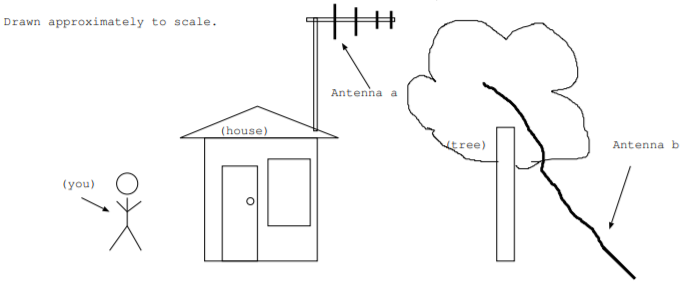
- Approximate the wavelength that antenna a is designed to operate at.
- Approximate the frequency that antenna b is designed to operate at.
- Which antenna most likely has parasitic elements: antenna a, antenna b, both, or neither? Explain your choice.
- Which antenna do you expect to be more isotropic: antenna a, antenna b, or would they be about the same? Explain your choice.
- Which antenna is more likely to be used as a receiver than a transmitter: antenna a, antenna b, or both antennas about equal? Explain your choice.
4.3. Some speculate that alien civilizations might be able to watch TV programs that escape the earth's atmosphere. To get an idea of the likelihood for this to occur, consider an isotropic antenna in outer space transmitting a \(200 \text{ MHz}\) TV signal.
Assume that the alien civilization uses an antenna with surface area \(0.5 m^2\) and has the technology to detect a signal with power as low as \(5 \cdot 10^{-22} W\). What is the minimum power that must be transmitted for detection to occur at a distance of 1.0 light year?
4.4. Project ELF, described in Sec. 4.4.1, was an extremely low frequency, \(76 \text{ Hz}\), radio system set by the military to communicate with submarines. It had facilities near Clam Lake, Wisconsin and Republic, Michigan, 148 miles apart [52]. Because these facilities were located a fraction of a wavelength apart, antennas at these locations acted as part of a single array. The length of all antenna elements was 84 miles [52]. Assume it took 18 minutes to transmit a three letters message using 8 bit ASCII, and assume signals travel close to the speed of light in free space.
- Calculate the ratio of the distance between the transmitting facilities to the wavelength.
- Calculate the ratio of the length of all antenna elements to the wavelength.
- What was the speed of communication in bits per second?
- How many wavelengths long were each bit?
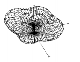
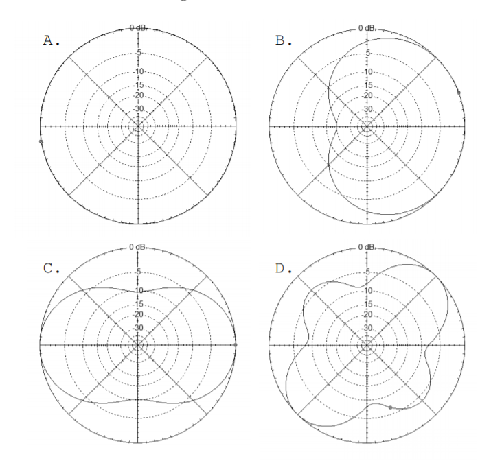
4.5. Match the following plots or antenna descriptions with their azimuth plots.
1. An antenna with 3D plot shown below
2. An isotropic antenna
3. An antenna with nulls at \(\pm 900\)
4. An antenna with a gain of around \(19 \text{dB}\)
4.6. Radiation pattern plots are for a particular transmitting antenna are shown. They were plotted with EZNEC. The azimuth plot is on the left, and the elevation plot is on the right. The antenna is designed to operate at at \(360 \text{ MHz}\). Use the plots to answer the following questions.
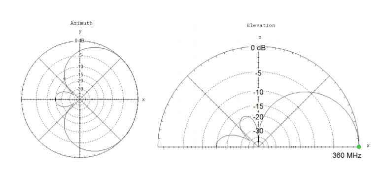
- Assume a person 100 m away and receiving signal from the antenna in the front direction (along the \(\hat{a}_x\) axis) receives a signal of 15 W. Approximately how strong of a signal would the person receive by standing 100 m away from the transmitter along the \(\hat{a}_y\) axis (in watts)?
- Find the (power) \(\text{F/B ratio}\) in \(\text{dB}\).
- According to the azimuth plot, at approximately what angle are the nulls for this antenna?
- What wavelength is this antenna designed to operate at?
4.7. Figure 4.4.2 show the radiation pattern plots for a quad antenna designed to operate at \(f = 21.2 \text{ MHz}\). The upper left plot shows the azimuth plot, the upper right plot shows the elevation plot. The lower left plot shows the 3D radiation pattern, and the lower right plot shows the antenna elements. They were plotted with EZNEC software.
(a) Find the wavelength the antenna is designed to operate at.
(b) Find \(\left[\frac{|\overrightarrow{E}_{front}|}{|\overrightarrow{E}_{back}|}\right]_{dB}\), the field front to back ratio of the antenna in \(\text{dB}\).
(c) Find \(\left[\frac{|P_{front}|}{|P_{back}|}\right]_{dB}\), the power front to back ratio in \(\text{dB}\).
(d) Find \(\left[\frac{|P_{front}|}{|P_{back}|}\right]_{lin}\), the power front to back ratio on a linear scale.
(e) Assume the electric field intensity 50 m away measured along the \(\phi = 45^{\circ}\) axis (in the \(z = 0\) plane) is \(5 \frac{V}{m}\). Find the electric field intensity 50 m away measured along the \(\phi = 135^{\circ}\) axis (in the \(z = 0\) plane).
4.8. Radiation pattern plots for a particular transmitting antenna are shown. They were plotted with EZNEC. The azimuth plot is on the left, and the elevation plot is on the right.
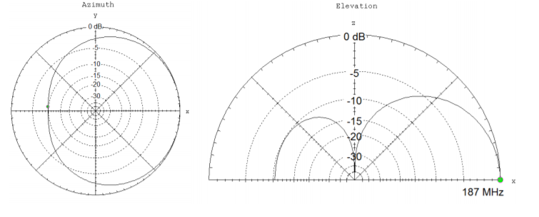
(a) Is this antenna isotropic? Justify your answer.
(b) The antenna is designed to operate at a frequency of \(187 \text{ MHz}\). What is the corresponding wavelength?
(c) Find the (power) \(\text{F/B ratio}\) in \({dB}\).
(d) The signal 100 m from the transmitting antenna in the front direction (\(\phi = 0\)) is measured to be \(|\overrightarrow{E}| = 50 \frac{V}{m}\). What is the electric field strength of the signal in \(\frac{V}{m}\) at 100 m from the antenna in the \(\phi = 45^{\circ}\) direction?
(e) Radiation pattern plots do not apply for all distances from the antenna. Roughly for what distances away are the radiation plots valid?
4.9. Determine if the following electromagnetic waves are linearly polarized, right circularly polarized, left circularly polarized, right elliptically polarized, or left elliptically polarized. All of these waves travel in the \(\hat{a}_z\) direction, and \(\omega\) is a constants. (This is a modified version of P3.34 from [11].)
(a) \(\overrightarrow{E} =10\cos(\omega t - 8z) \hat{a}_x + 10\sin(\omega t - 8z) \hat{a}_y\)
(b) \(\overrightarrow{E} =10\cos(\omega t - 8z) \hat{a}_x + 10\sin(\omega t - 8z) \hat{a}_y\)
(c) \(\overrightarrow{E} =10\cos(\omega t - 8z + \frac{\pi}{4}) \hat{a}_x + 20\sin(\omega t - 8z + \frac{\pi}{4}) \hat{a}_y\)
(d) \(\overrightarrow{E} =10\cos(\omega t - 8z) \hat{a}_x - 10\sin(\omega t - 8z) \hat{a}_y\)