
3.4: Resistance
- Page ID
- 48129

Resistance Between Two Electrodes
Two conductors maintained at a potential difference V within a conducting medium will each pass a total current I, as shown in Figure 3-15. By applying the surface integral form of charge conservation in Section 3.2.1 to a surface S' which surrounds both electrodes but is far enough away so that J and D are negligibly small, we see that the only nonzero current contributions are from the terminal wires that pass through the surface. These must sum to zero so that the currents have equal magnitudes but flow in opposite directions. Similarly, applying charge conservation to a surface S just enclosing the upper electrode shows that the current I entering the electrode via the wire must just equal the total current (conduction plus displacement) leaving the electrode. This total current travels to the opposite electrode and leaves via the connecting wire.
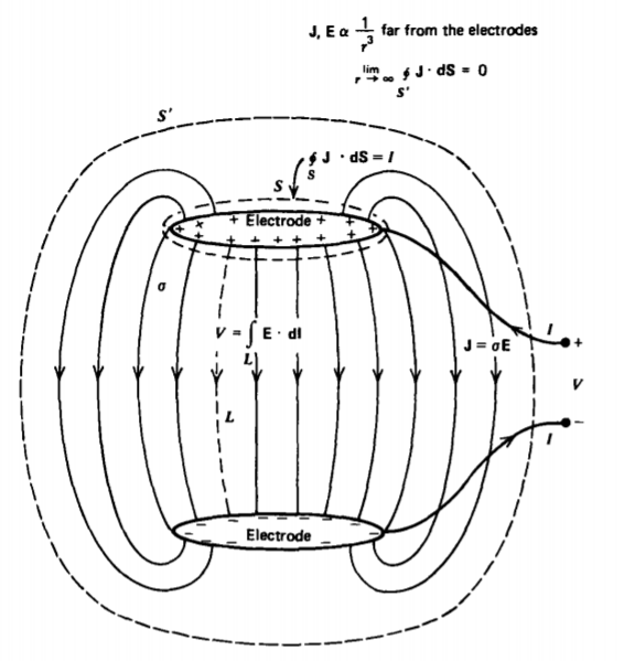
The dc steady-state ratio of voltage to current between the two electrodes in Figure 3-15 is defined as the resistance:
\[\textrm{R} = \frac{V}{I} \textrm{ohm}[ \textrm{kg m}^{2} \textrm{s}^{-3} \textrm{A}^{-2}] \label{eq1} \]
For an arbitrary geometry, Equation \ref{eq1} can be expressed in terms of the fields as
\[\textrm{R} = \frac{\int_{L} \textbf{E} \cdot \textbf{dl}}{\oint_{S} \textbf{J} \cdot \textbf{dS}} = \frac{\int_{L} \textbf{E} \cdot \textbf{dl}}{\oint_{S} \sigma \textbf{E} \cdot \textbf{dS}} \label{eq2} \]
where S is a surface completely surrounding an electrode and L is any path joining the two electrodes. Note that the field line integral is taken along the line from the high to low potential electrode so that the voltage difference V is equal to the positive line integral. From Equation \ref{eq2}, we see that the resistance only depends on the geometry and conductivity \(\sigma\), and not on the magnitude of the electric field itself. If we were to increase the voltage by any factor, the field would also increase by this same factor everywhere so that this factor would cancel out in the ratio of Equation \ref{eq2}. The conductivity \(\sigma\) may itself be a function of position.
Parallel Plate Resistor
Two perfectly conducting parallel plate electrodes of arbitrarily shaped area A and spacing l enclose a cylinder of material with Ohmic conductivity \(\sigma\), as in Figure 3-16a. The current must flow tangential to the outer surface as the outside medium being free space has zero conductivity so that no current can pass through the interface. Because the tangential component of electric field is continuous, a field does exist in the free space region that decreases with increasing distance from the resistor. This three-dimensional field is difficult to calculate because it depends on three coordinates.
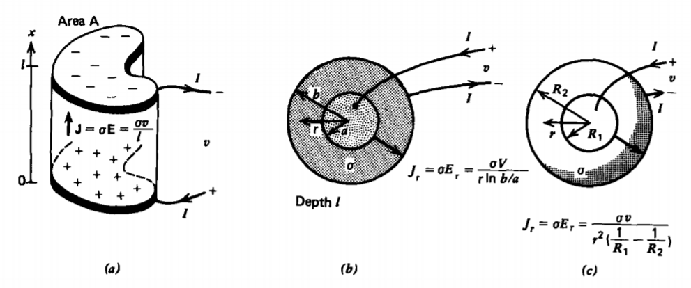
The electric field within the resistor is much simpler to calculate because it is perpendicular to the electrodes in the x direction. Gauss's law with no volume charge then tells us that this field is constant:
\[\nabla \cdot (\varepsilon \textbf{E}) = 0 \Rightarrow \frac{dE_{x}}{dx} = 0 \Rightarrow E_{x} = E_{0} \]
However, the line integral of E between the electrodes must be the applied voltage \(v\):
\[\int_{0}^{l} E_{x} dx = v \Rightarrow E_{0} = v/l \]
The current density is then
\[\textbf{J} = \sigma E_{0} \textbf{i}_{x} = (\sigma v/l) \textbf{i}_{x} \]
so that the total current through the electrodes is
\[I = \oint_{S} \textbf{J} \cdot \textbf{dS} = (\sigma v/l)A \]
where the surface integral is reduced to a pure product because the constant current density is incident perpendicularly on the electrodes. The resistance is then
\[\textrm{R} = \frac{v}{I} = \frac{l}{\sigma A} = \frac{\textrm{spacing}}{\textrm{(conductivity)(electrode area)}} \]
Typical resistance values can vary over many orders of magnitude. If the electrodes have an area A = 1 cm2 (10-4 m2) with spacing l = 1 mm (10-3 m) a material like copper has a resistance \(R \approx 0.17 \times 10^{-6}\) ohm while carbon would have a resistance \(R \approx 1.4 \times 10^{4}\) ohm. Because of this large range of resistance values sub-units often used are micro-ohms (\(1 \mu \Omega = 10^{-6} \Omega\)), milli-ohms (\(1 \textrm{ m} \Omega = 10^{-3} \Omega\)), kilohm (\(1 \: k \Omega = 10^{3} \Omega\)), and megohms (\(1 \textrm{ M} \Omega =10^{6} \Omega\)), where the symbol \(\Omega\) is used to represent the unit of ohms.
Although the field outside the resistor is difficult to find, we do know that for distances far from the resistor the field approaches that of a point dipole due to the oppositely charged electrodes with charge density
\[\sigma_{f}(x = 0) = - \sigma_{f}(x = l) = \varepsilon E_{0} = \varepsilon v/l \]
and thus dipole moment
\[\textbf{p} = - \sigma_{f}(x =0) A l \textbf{i}_{x} = - \varepsilon A v \textbf{i}_{x} \]
The minus sign arises because the dipole moment points from negative to positive charge. Note that (8) is only approximate because all of the external field lines in the free space region must terminate on the side and back of the electrodes giving further contributions to the surface charge density. Generally, if the electrode spacing I is much less than any of the electrode dimensions, this extra contribution is very small.
Coaxial Resistor
Two perfectly conducting coaxial cylinders of length l, inner radius a, and outer radius b are maintained at a potential difference v and enclose a material with Ohmic conductivity \(\sigma\), as in Figure 3-16b. The electric field must then be perpendicular to the electrodes so that with no free charge Gauss's law requires
\[\nabla \cdot (\varepsilon \textbf{E}) = 0 \Rightarrow \frac{1}{\textrm{r}} \frac{\partial}{\partial \textrm{r}} (\textrm{r} E_{\textrm{r}}) = 0 \Rightarrow E_{\textrm{r}} = \frac{c}{\textrm{r}} \]
where c is an integration constant found from the voltage condition
\[\int_{a}^{b} E_{\textrm{r}} d \textrm{r} = c \ln \textrm{r} \big|_{a}^{b} = v \Rightarrow c = \frac{v}{\ln (b/a)} \]
The current density is then
\[\textbf{J}_{\textrm{r}} = \sigma E_{\textrm{r}} = \frac{\sigma v}{\textrm{r} \ln (b/a)} \]
with the total current at any radius r being a constant
\[I = \int_{z=0}^{l} \int_{\phi=0}^{2\pi} J_{\textrm{r}} \textrm{r} d \phi dz = \frac{\sigma v 2 \pi l}{\ln(b/a)} \]
so that the resistance is
\[\textrm{R} = \frac{v}{I} = \frac{\ln (b/a)}{2 \pi \sigma l} \]
Spherical Resistor
We proceed in the same way for two perfectly conducting concentric spheres at a potential difference \(v\) with inner radius \(R_1\) and outer radius \(R_2\), as in Figure 3-16c. With no free charge, symmetry requires the electric field to be purely radial so that Gauss's law yields
\[\nabla \cdot (\varepsilon \textbf{E}) = 0 \Rightarrow \frac{1}{r^{2}} \frac{\partial}{\partial r}(r^{2}E_{r}) = 0 \Rightarrow E_{r} = \frac{c}{r^{2}} \]
where c is a constant found from the voltage condition as
\[\int_{R_{1}}^{R_{2}} E_{r}dr = - \frac{c}{r} \big|_{R_{1}}^{R_{2}} = v \Rightarrow c = \frac{v}{(1/R_{1}-1/R_{2})} \]
The electric field and current density are inversely proportional to the square of the radius
\[J_{r} = \sigma E_{r} = \frac{\sigma v}{r^{2}(1/R_{1} - 1/R_{2})} \]
so that the current density is constant at any radius \(r\)
\[I = \int_{\phi = 0}^{2 \pi} \int_{\theta =0}^{\pi} J_{r}r^{2} \sin \theta d \theta d \phi = \frac{4 \pi \sigma v}{(1/R_{1} - 1/R_{2})} \]
with resistance
\[\textrm{R} = \frac{v}{I} = \frac{(1/R_{1}-1/R_{2})}{4 \pi \sigma} \]