
7.10: Applications to Optics
- Page ID
- 48165

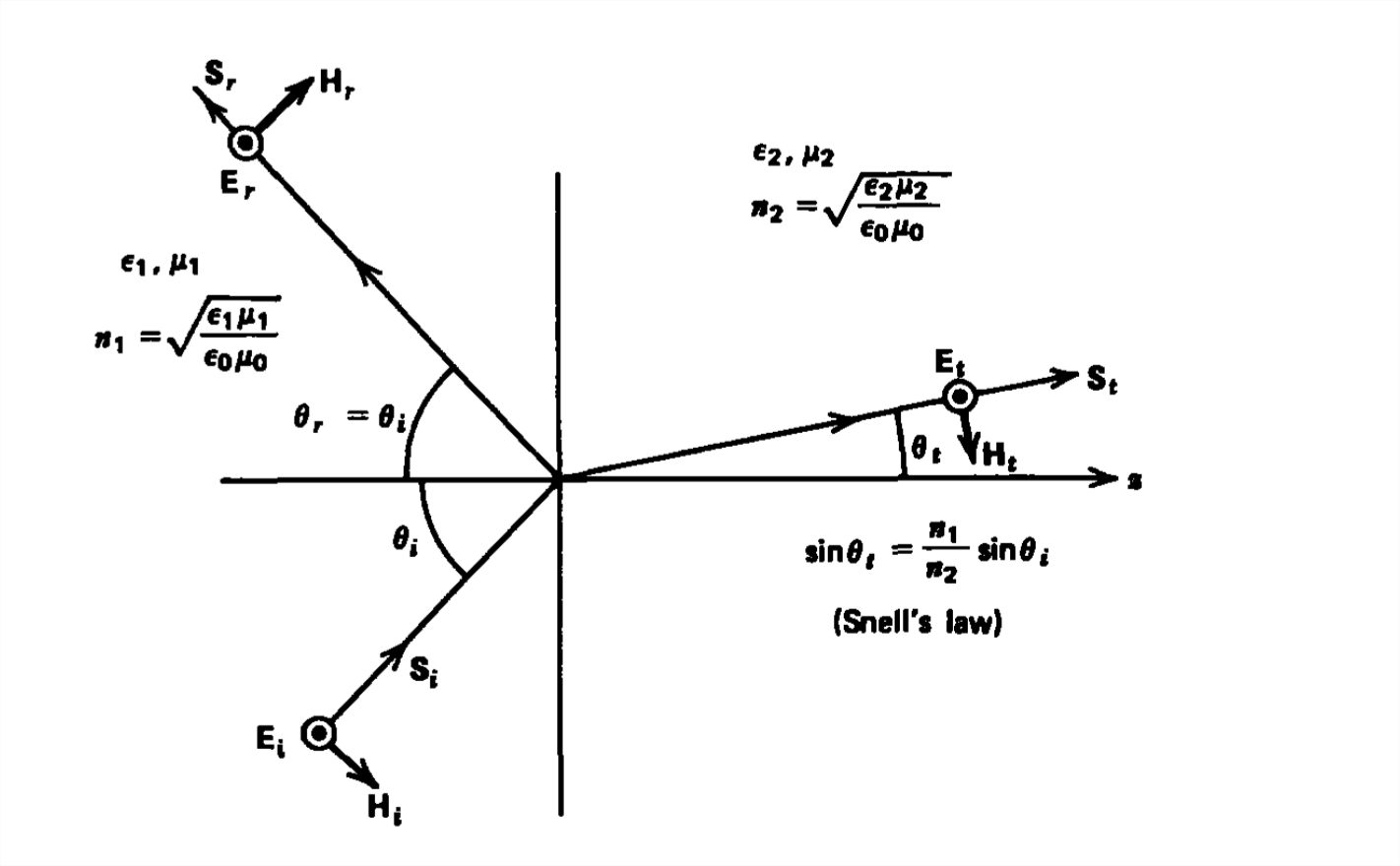
Reflection and refraction of electromagnetic waves obliquely incident upon the interface between dissimilar linear lossless media are governed by the two rules illustrated in Figure 7-19:
- The angle of incidence equals the angle of reflection.
- Waves incident from a medium of high light velocity (low index of refraction) to one of low velocity (high index of refraction) are bent towards the normal. If the wave is incident from a low velocity (high index) to high velocity (low index) medium, the light is bent away from the normal. The incident and refracted angles are related by Snell's law.
Most optical materials, like glass, have a permeability of free space \(\mu _{0}\). Therefore, a Brewster's angle of no reflection only exists if the \(\textbf{H}\) field is parallel to the boundary.
At the critical angle, which can only exist if light travels from a high index of refraction material (low light velocity) to one of low index (high light velocity), there is a transmitted field that decays with distance as a nonuniform plane wave. However, there is no time-average power carried by this evanescent wave so that all the time-average power is reflected. This section briefly describes various applications of these special angles and the rules governing reflection and refraction.
Reflections from a Mirror
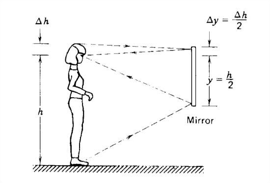
A person has their eyes at height \(h\) above their feet and a height \(\Delta h\) below the top of their head, as in Figure 7-20. A mirror in front extends a distance \(\Delta y\) above the eyes and a distance \(y\) below. How large must \(y\) and \(\Delta y\) be so that the person sees their entire image? The light reflected off the person into the mirror must be reflected again into the person's eyes. Since the angle of incidence equals the angle of reflection, Figure 7-20 shows that \(\Delta y=\Delta h/2\) and \(y =h/2\).
Lateral Displacement of a Light Ray
A light ray is incident from free space upon a transparent medium with index of refraction \(n\) at angle \(\theta _{i}\), as shown in Figure 7-21. The angle of the transmitted light is given by Snell's law:
\[ \sin \theta _{t}=\left ( 1/n \right )\sin \theta _{i} \]
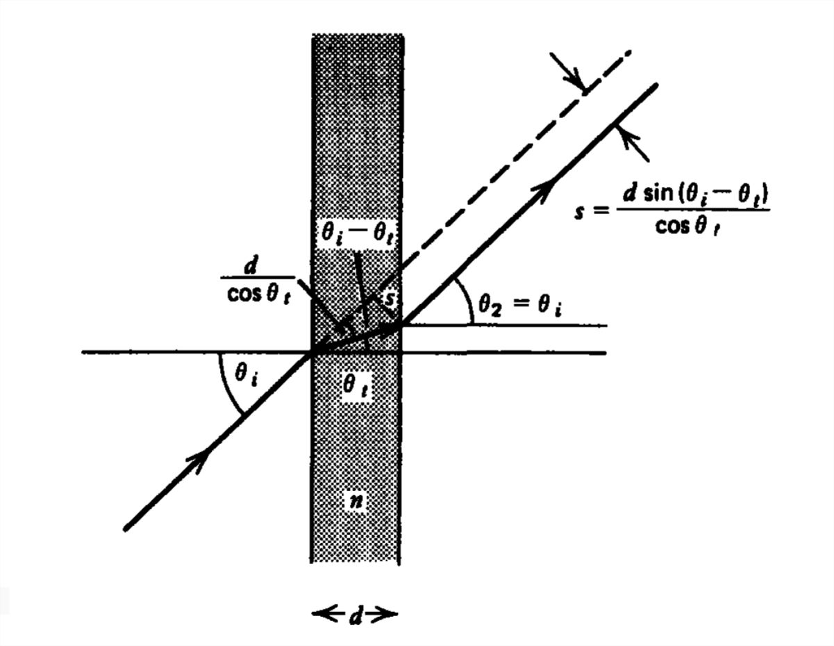
When this light hits the second interface, the angle \(\theta _{t}\) is now the incident angle so that the transmitted angle \(\theta _{2}\) is again given by Snell's law:
\[ \sin \theta _{2}=n\sin \theta _{t}=\sin \theta _{i} \]
so that the light exits at the original incident angle \(\theta _{i}\). However, it is now shifted by the amount:
\[ s=\frac{d\sin \left ( \theta _{i}-\theta _{t} \right )}{\cos \theta _{t}} \]
If the plate is glass with refractive index \(n = 1.5\) and thickness \(d = 1 \textrm{mm}\) with incident angle \( \theta _{i}=30^{\circ }\), the angle \( \theta _{t}\) in the glass is
\[ \sin \theta _{t}=0.33\Rightarrow \theta _{t}=19.5^{\circ } \]
so that the lateral displacement is \(s = 0.19 \textrm{mm}\).
Polirization By Reflection
Unpolarized light is incident upon the piece of glass in Section 7-10-2 with index of refraction \(n = 1.5\). Unpolarized light has both \(\textbf{E}\) and \(\textbf{H}\) parallel to the interface. We assume that the permeability of the glass equals that of free space and that the light is incident at the Brewster's angle \(\theta _{B}\) for light polarized with \(\textbf{H}\) parallel to the interface. The incident and transmitted angles are then
\[ \tan \theta _{B}=\sqrt{\varepsilon /\varepsilon _{0}}=n\Rightarrow \theta _{B}=56.3^{\circ }\\
\tan \theta _{t}=\sqrt{\varepsilon _{0}/\varepsilon}=1/n\Rightarrow \theta _{t}=33.7^{\circ } \]
The Brewster's angle is also called the polarizing angle because it can be used to separate the two orthogonal polarizations. The polarization, whose \(\textbf{H}\) field is parallel to the interface, is entirely transmitted at the first interface with no reflection. The other polarization with electric field parallel to the interface is partially transmitted and reflected. At the second (glass-free space) interface the light is incident at angle \(\theta _{t}\). From (5) we see that this angle is the Brewster's angle with \(\textbf{H}\) parallel to the interface for light incident from the glass side onto the glass-free space interface. Then again, the H parallel to the interface polarization is entirely transmitted while the \(\textbf{E}\) parallel to the interface polarization is partially reflected and partially transmitted. Thus, the reflected wave is entirely polarized with electric field parallel to the interface. The transmitted waves, although composed of both polarizations, have the larger amplitude with \(\textbf{H}\)
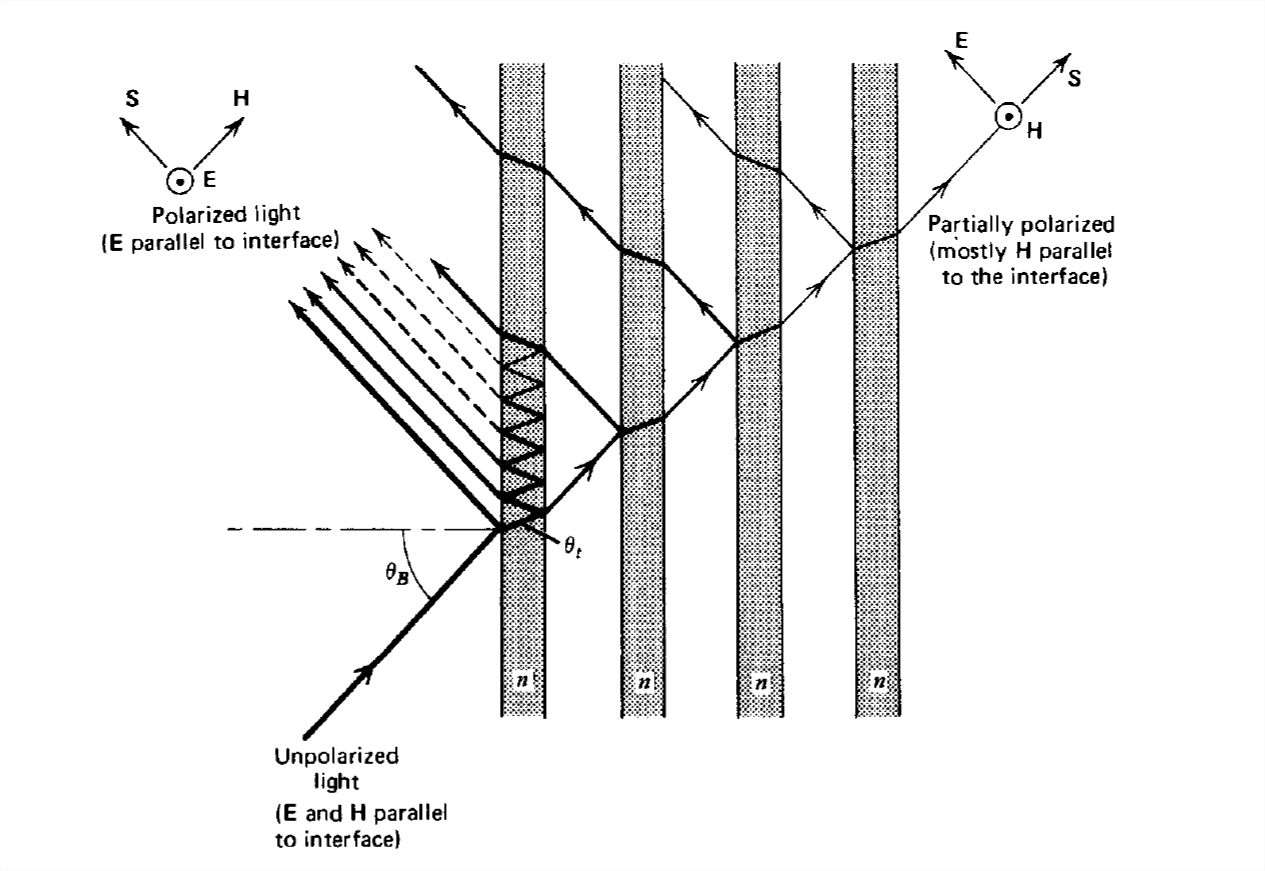
parallel to the interface because it was entirely transmitted with no reflection at both interfaces.
By passing the transmitted light through another parallel piece of glass, the polarization with electric field parallel to the interface becomes further diminished because it is partially reflected, while the other polarization is completely transmitted. With more glass elements, as in Figure 7-22, the transmitted light can be made essentially completely polarized with \(\textbf{H}\) field parallel to the interface.
Light Propagation In Water
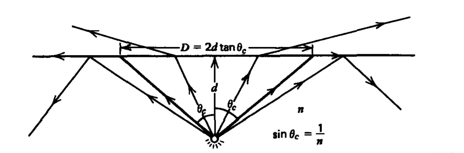
(a) Submerged Source
A light source is a distance d below the surface of water with refractive index \(n = 1.33\), as in Figure 7-23. The rays emanate from the source as a cone. Those rays at an angle from the normal greater than the critical angle,
\[ \sin \theta _{c}=1/n\Rightarrow \theta _{c}=48.8^{\circ } \]
are not transmitted into the air but undergo total internal reflection. A circle of light with diameter
\[ D=2d\tan \theta _{c}\approx 2.28d \]
then forms on the water's surface due to the exiting light.
(b) Fish Below a Boat
A fish swims below a circular boat of diameter \(D\), as in Figure 7-24. As we try to view the fish from the air above, the incident light ray is bent towards the normal. The region below the boat that we view from above is demarcated by the light rays at grazing incidence to the surface \(\left ( \theta _{i}=\pi /2 \right )\) just entering the water \((n = 1.33)\) at the sides of the boat. The transmitted angle of these light rays is given from Snell's law as
\[ \sin \theta _{t}=\frac{\sin \theta _{i}}{n}=\frac{1}{n}\Rightarrow \theta _{t}=48.8^{\circ } \]
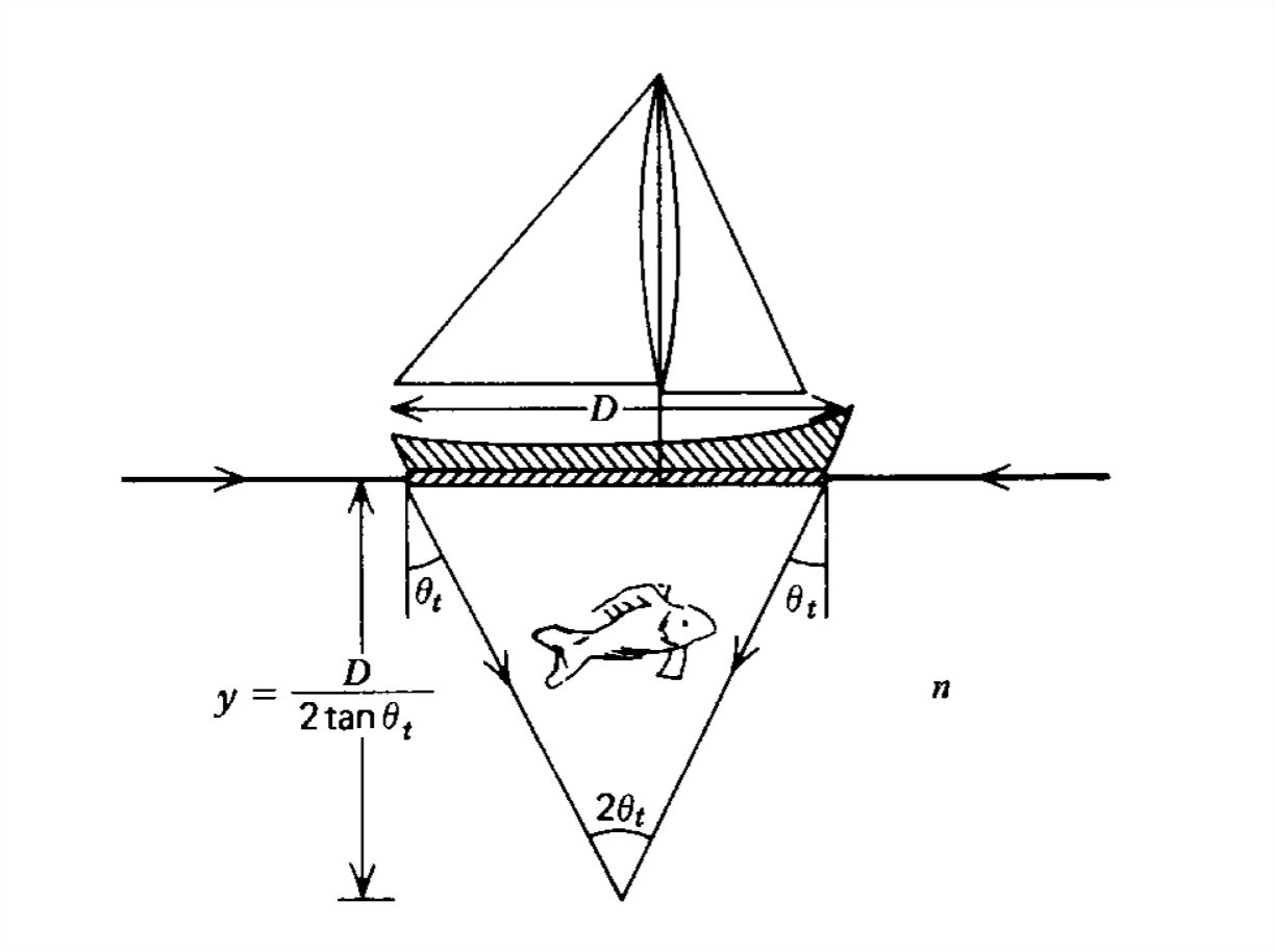
These rays from all sides of the boat intersect at the point a distance \(y\) below the boat, where
\[ \tan \theta _{t}=\frac{D}{2y} \Rightarrow y=\frac{D}{2\tan \theta_{t}}\approx 0.44D \]
If the fish swims within the cone, with vertex at the point \(y\) below the boat, it cannot be viewed from above.
Totally Reflecting Prisms
The glass isoceles right triangle in Figure 7-25 has an index of refraction of \(n = 1.5\) so that the critical angle for total
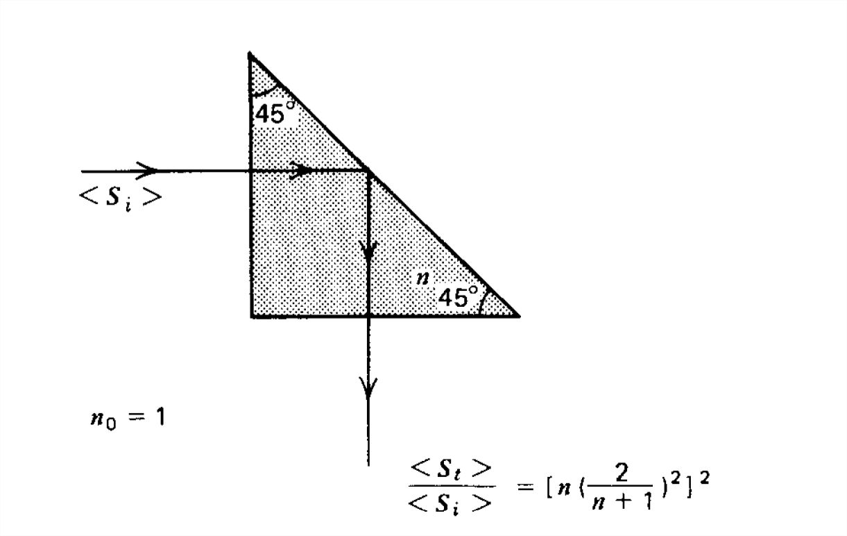
internal reflection is
\[ \sin \theta _{c}=\frac{1}{n}=\frac{1}{1.5}\Rightarrow \theta _{c}=41.8^{\circ } \]
The light is normally incident on the vertical face of the prism. The transmission coefficient is then given in Section 7-6-1 as
\[ T_1=\frac{\hat{E}_{t}}{\hat{E}_{i}}=\frac{2\eta }{\eta +\eta _{0}}=\frac{2/n}{1+1/n}=\frac{2}{n+1}=0.8 \]
where because the permeability of the prism equals that of free space \(n=\sqrt{\varepsilon /\varepsilon _{0}}\) while \(\eta /\eta _{0}=\sqrt{\varepsilon _{0} /\varepsilon}=1/n\). The transmitted light is then incident upon the hypotenuse of the prism at an angle of \(45^{\circ }\), which exceeds the critical angle so that no power is transmitted and the light is totally reflected being turned through a right angle. The light is then normally incident upon the horizontal face with transmission coefficient:
\[ T_2=\frac{\hat{E}_{2}}{0.8\hat{E}_{i}}=\frac{2\eta _{0} }{\eta +\eta _{0}}=\frac{2}{1/n+1}=\frac{2n}{n+1}=1.2 \]
The resulting electric field amplitude is then
\[ \hat{E}_{2}=T_{1}T_{2}\hat{E}_{i}=0.96\hat{E}_{i} \]
The ratio of transmitted to incident power density is
\[ \frac{<S>}{<S_{i}>}=\frac{\frac{1}{2}\left | \hat{E}_{2} \right |^{2}/\eta _{0}}{\frac{1}{2}\left | \hat{E}_{i} \right |^{2}/\eta _{0}}=\frac{\left | \hat{E}_{2} \right |^{2}}{\left | \hat{E}_{i} \right |^{2}}=\left ( \frac{24}{25} \right )^{2}\approx 0.92 \]
This ratio can be increased to unity by applying a quarter-wavelength-thick dielectric coating with index of refraction \(n_{coating}=\sqrt{n}\), as developed in Example 7-1. This is not usually done because the ratio in (14) is already large without the expense of a coating.
Fiber Optics
(a) Straight Light Pipe
Long hin fibers of transparent material can guide light along a straight path if the light within the pipe is incident upon the wall at an angle greater than the critical angle \(\left ( \sin \theta _{c} \right )=1/n\):
\[\sin \theta _{2}=\cos \theta _{t}\geq \sin \theta _{c} \]
The light rays are then totally internally reflected being confined to the pipe until they exit, as in Figure 7-26. The
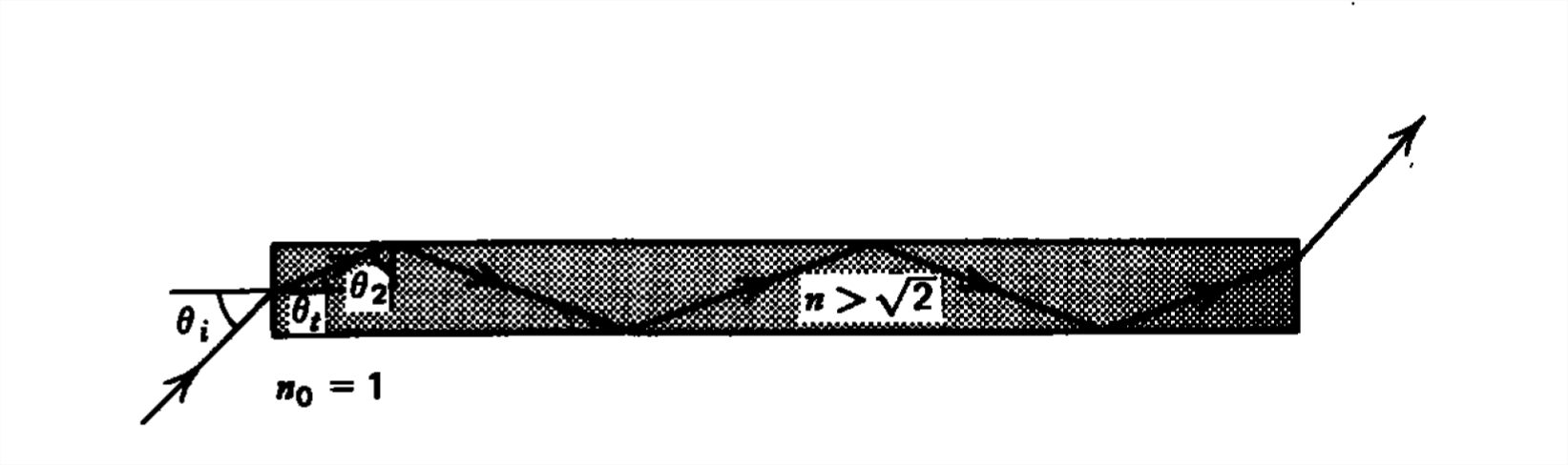
incident angle is related to the transmitted angle from Snell's law,
\[ \sin \theta _{t}=\left ( 1/n \right )\sin \theta _{i} \]
so that (15) becomes
\[ \cos\theta _{t}=\sqrt{1-\sin^{2} \theta _{t}}=\sqrt{1-\left ( 1/n^{2} \right )\sin^{2} \theta _{i}}\geq 1/n \]
which when solved for \(n\) yields
\[ n^{2}\geq 1+\sin^{2} \theta _{i} \]
If this condition is met for grazing incidence \(\left ( \theta _{i}=\pi /2 \right )\), all incident light will be passed by the pipe, which requires that
\[ n^{2}\geq 2\Rightarrow n\geq \sqrt{2} \]
Most types of glass have \(n\approx 1.5\) so that this condition is easily met.
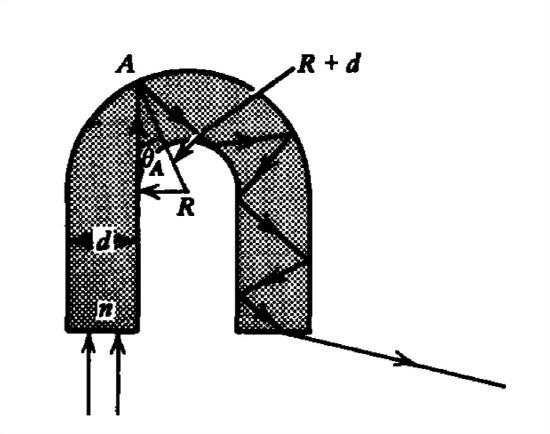
(b) Bent Fibers
Light can also be guided along a tortuous path if the fiber is bent, as in the semi-circular pipe shown in Figure 7-27. The minimum angle to the radial normal for the incident light shown is at the point \(A\). This angle in terms of the radius of the bend and the light pipe width must exceed the critical angle
\[ \sin \theta _{A}=\frac{R}{R+d}\geq \sin \theta _{c} \]
so that
\[ \frac{R/d}{R/d+1}\geq \frac{1}{n} \]
which when solved for \(R/d\) requires
\[\frac{R}{d}\geq \frac{1}{n-1} \]