
1.7: Thevenin and Norton Equivalent Circuits
- Page ID
- 55513

A particularly important ramification of the property of linearity is expressed in the notion of equivalent circuits. To wit: if we are considering the response of a network at any given terminal pair, that is a pair of nodes that have been brought out to the outside world, it follows from the properties of linearity that, if the network is linear, the output at a single terminal pair (either voltage or current) is the sum of two components:
- The response that would exist if the excitation at the terminal pair were zero and
- The response forced at the terminal pair by the exciting voltage or current.
This notion may be expressed with either voltage or current as the response. These yield the Thevenin and Norton equivalent networks, which are exactly equivalent. At any terminal pair, the properties of a linear network may be expressed in terms of either Thevenin or Norton equivalents. The Thevenin equivalent circuit is shown in Figure 16, while the Norton equivalent circuit is shown in Figure 17.
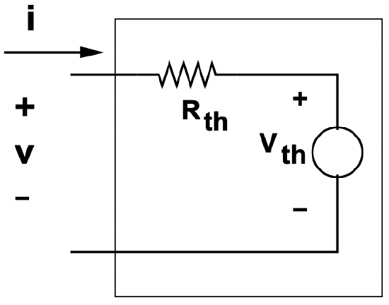 Figure 16: Thevenin Equivalent Network
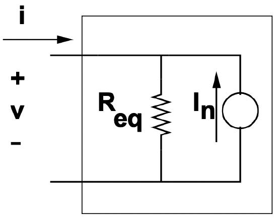 Figure 17: Norton Equivalent Network
The Thevenin and Norton equivalent networks have the same impedance. Further, the equivalent sources are related by the simple relationship:
\[\ V_{T h}=R_{e q} I_{N}\label{13} \]
The Thevenin Equivalent Voltage, the source internal to the Thevenin equivalent network, is the same as the open circuit voltage, which is the voltage that would appear at the terminals of the equivalent circuit were it to be open circuited. Similarly, the Norton Equivalent Current is the same as minus the short circuit current.
To consider how we might use these equivalent networks, consider what would happen if the Wheatstone bridge were connected by some resistance across its output, as shown in Figure 18
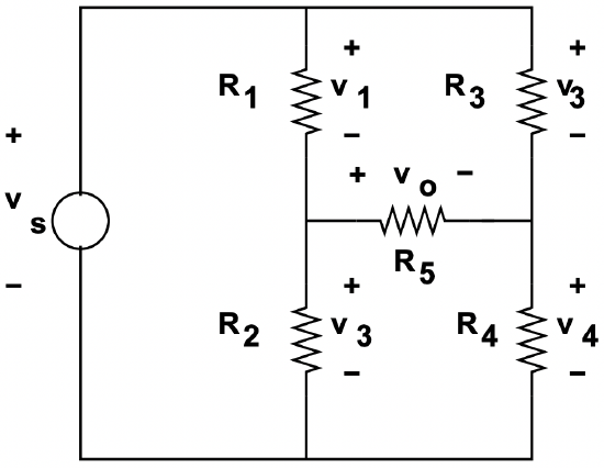 Figure 18: Wheatstone Bridge With Output Resistance
The analysis of this situation is simplified substantially if one recognizes that each side of the bridge can be expressed as either a Thevenin or Norton equivalent network. We may proceed to solve the problem by finding the equivalent networks for each side, then paste them together to form the whole solution. So: consider the equivalent network for the left-hand side of the network, formed by the elements \(\ V\), \(\ R_{1}\) and \(\ R_{2}\). This is shown in Figure 19.
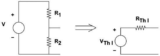 Figure 19: Construction of Equivalent Circuit
Where, here, the components of the equivalent circuit are:
\(\ \begin{aligned}
v_{T h l} &=V \frac{R_{2}}{R_{1}+R_{2}} \\
R_{e q l} &=R_{1} \| R_{2}
\end{aligned}\)
Similarly, the right side of the network is found to have an equivalent source and resistance:
\(\ \begin{aligned}
v_{T h r} &=V \frac{R_{4}}{R_{3}+R_{4}} \\
R_{e q r} &=R_{3} \| R_{4}
\end{aligned}\)
And the whole thing behaves as the equivalent circuit shown in Figure 20
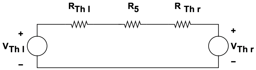 Figure 20: Equivalent Circuit
This is, of course, easily solved for the current through, and hence the voltage across, the resistance \(\ R_{5}\), which was desired in the first place:
\(\ v_{5}=\left(v_{T h l}-v_{T h r}\right) \frac{R_{5}}{R_{5}+r_{e q l}+r_{e q r}}=V\left(\frac{R_{2}}{R_{1}+R_{2}}-f r a c R_{4} R_{3}+R_{4}\right) \frac{R_{5}}{R_{5}+R_{1}|| R_{2}+R_{3} \| R_{4}}\)