
3.4: Transformers
- Page ID
- 55546

Transformers are essential parts of most power systems. Their role is to convert electrical energy at one voltage to some other voltage. We will deal with transformers as electromagnetic elements later on in this subject, but for now it will be sufficient to use a simplified model for the transformer which we will call the ideal transformer. This is a two-port circuit element, shown in Figure 14.
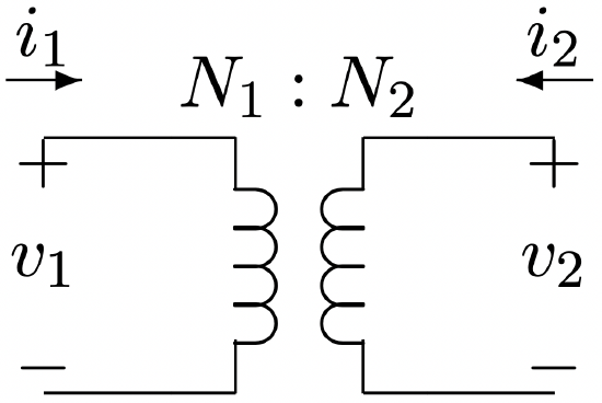 Figure 14: Ideal Transformer
The ideal transformer as a network element constrains its terminal variables in the following way:
\[\ \frac{v_{1}}{N_{1}}=\frac{v_{2}}{N_{2}}\label{33} \]
\[\ N_{1} i_{1}=-N_{2} i_{2}\label{34} \]
As it turns out, this is not a terribly bad model for the behavior of a real transformer under most circumstances. Of course, we will be interested in fine points of transformer behavior and behavior under pathological operating conditions, and so will eventually want a better model. For now, it is sufficient to note just a few things about how the transformer works.
- In normal operation, we select a transformer turns ratio \(\ \frac{N_{1}}{N_{2}}\) so that the desired voltages appear at the proper terminals. For example, to convert 13.8 kV distribution voltage to the 120/240 volt level suitable for residential or commercial single phase service, we would use a transformer with turns ratio of \(\ \frac{13800}{240}=57.5\). To split the low voltage in half, a center tap on 240 the low voltage winding would be used.
- \[\ p_{1}+p_{2}=v_{1} i_{1}+v_{2} i_{2}=0\label{35} \]
- The transformer also tends to transform impedances. To show how this is, look at Figure 15. Here, some impedance is connected to one side of an ideal transformer. See that it is possible to find an equivalent impedance viewed from the other side of the transformer.
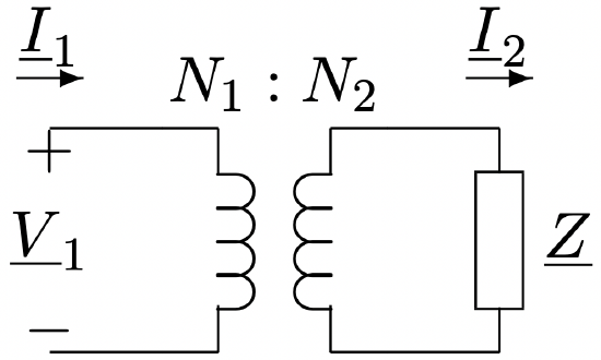 Figure 15: Impedance Transformation
Noting that
\(\ \underline{I}_{2}=-\frac{N_{1}}{N_{2}} \underline{I}_{1}\)
and that
\(\ \underline{V}_{2}=-\underline{Z} \underline{I}_{2}\)
Then the ratio between input voltage and current is:
\[\ \underline{V}_{1}=\frac{N_{1}}{N_{2}} \underline{V}_{2}=\left(\frac{N_{1}}{N_{2}}\right)^{2} \underline{I}_{1}\label{36} \]