
3.5: Three-Phase Transformers
- Page ID
- 55547

A three-phase transformer is simply three single phase transformers. The complication in these things is that there are a number of ways of winding them, and a number of ways of interconnecting them. We will have more to say about windings later. For now, consider interconnections. On either “side” of a transformer connection (i.e. the high voltage and low voltage sides), it is possible to connect transformer windings either line to neutral (wye), or line to line (delta). Thus we may speak of transformer connections being wye-wye, delta-delta, wye-delta, or delta-wye.
Ignoring certain complications that we will have more to say about shortly, connection of transformers in either wye-wye or delta-delta is reasonably easy to understand. Each of the line-to-neutral (in the case of wye-wye), or line-to-line (in the case of delta-delta) voltages is transformed by one of the three transformers. On the other hand, the interconnections of a wye-delta or delta-wye transformer are a little more complex. Figure 16 shows a delta-wye connection, in what might be called “wiring diagram” form. A more schematic (and more common) form of the same picture is shown in Figure 17. In that picture, winding elements that appear parallel are wound on the same core segment, and so constitute a single phase transformer.
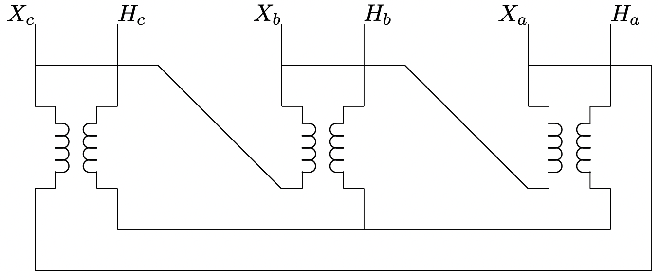 Figure 16: Delta-Wye Transformer Connection
Now: assume that \(\ N_{\Delta}\) and \(\ N_{Y}\) are numbers of turns. If the individual transformers are considered to be ideal, the following voltage and current constraints exist:
\[\ v_{a Y}=\frac{N_{Y}}{N_{\Delta}}\left(v_{a \Delta}-v_{b \Delta}\right)\label{37} \]
\[\ v_{b Y}=\frac{N_{Y}}{N_{\Delta}}\left(v_{b \Delta}-v_{c \Delta}\right)\label{38} \]
\[\ v_{c Y}=\frac{N_{Y}}{N_{\Delta}}\left(v_{c \Delta}-v_{a \Delta}\right)\label{39} \]
\[\ i_{a \Delta}=\frac{N_{Y}}{N_{\Delta}}\left(i_{a Y}-i_{c Y}\right)\label{40} \]
\[\ i_{b \Delta}=\frac{N_{Y}}{N_{\Delta}}\left(i_{b Y}-i_{a Y}\right)\label{41} \]
\[\ i_{c \Delta}=\frac{N_{Y}}{N_{\Delta}}\left(i_{c Y}-i_{b Y}\right)\label{42} \]
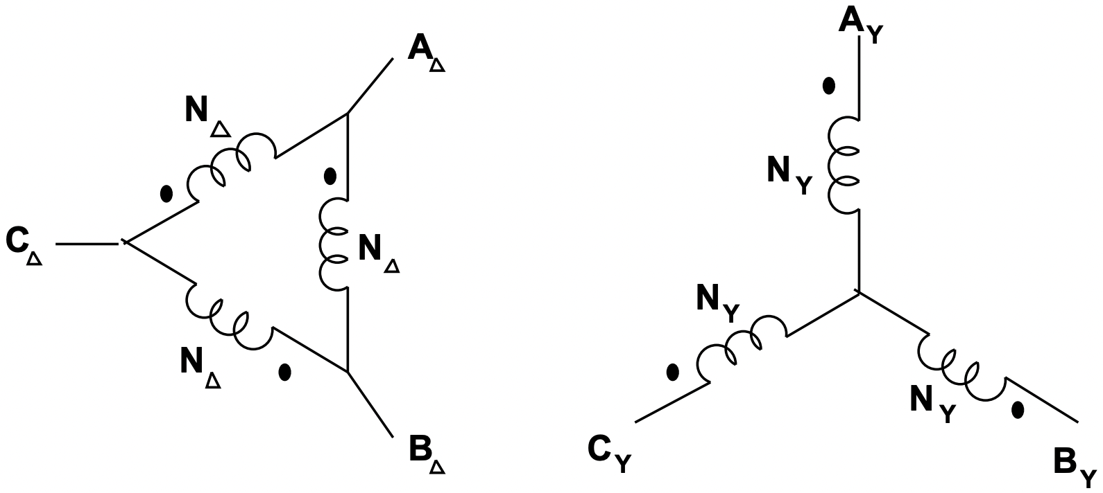 Figure 17: Schematic of Delta-Wye Transformer Connection
where each of the voltages are line-neutral and the currents are in the lines at the transformer terminals.
Now, consider what happens if a \(\ \Delta-Y\) transformer is connected to a balanced three- phase voltage source, so that:
\(\ \begin{array}{l}
v_{a \Delta}=R e\left(\underline{V} e^{j \omega t}\right) \\
v_{b \Delta}=\operatorname{Re}\left(\underline{V} e^{j\left(\omega t-\frac{2 \pi}{3}\right)}\right) \\
v_{c \Delta}=\operatorname{Re}\left(\underline{V} e^{j\left(\omega t+\frac{2 \pi}{3}\right)}\right)
\end{array}\)
Then, complex amplitudes on the \(\ wye\) side are:
\(\ \begin{array}{ll}
\underline{V}_{a Y}= & \frac{N_{Y}}{N_{\Delta}} \underline{V}\left(1-e^{-j \frac{2 \pi}{3}}\right)= & \sqrt{3} \frac{N_{Y}}{N_{\Delta}} \underline{V} e^{j \frac{\pi}{6}} \\
\underline{V}_{b Y}= & \frac{N_{Y}}{N_{\Delta}} \underline{V}\left(e^{-j \frac{2 \pi}{3}}-e^{j \frac{2 \pi}{3}}\right)= & \sqrt{3} \frac{N_{Y}}{N_{\Delta}} \underline{V} e^{-j \frac{\pi}{2}} \\
\underline{V}_{c Y}= & \frac{N_{Y}}{N_{\Delta}} \underline{V}\left(e^{j \frac{2 \pi}{3}}-1\right)= & \sqrt{3} \frac{N_{Y}}{N_{\Delta}} \underline{V} e^{j \frac{5 \pi}{6}}
\end{array}\)
Two observations should be made here:
- The ratio of voltages (that is, the ratio of either line-line or line-neutral) is different from the turns ratio by a factor of \(\ \sqrt{3}\).
- All \(\ wye\) side voltages are shifted in phase by 30o with respect to the delta side voltages.
Example
Suppose we have the following problem to solve:
A balanced three- phase wye-connected resistor is connected to the \(\ \Delta\) side of a \(\ Y-\Delta\) transformer with a nominal voltage ratio of
\(\ \frac{v_{\Delta}}{v_{Y}}=N\)
What is the impedance looking into the wye side of the transformer, assuming drive with a balanced source?
The situation is shown in Figure 18.
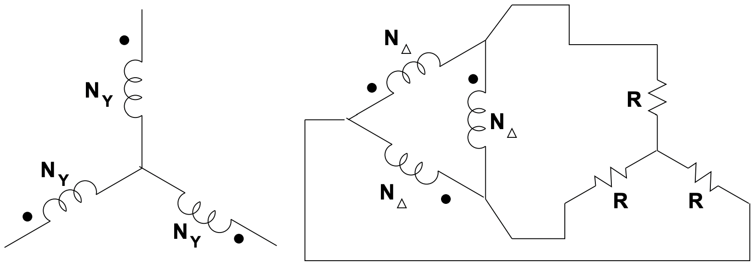 Figure 18: Example
It is important to remember the relationship between the voltage ratio and the turns ratio, which is:
\(\ \frac{v_{\Delta}}{v_{Y}}=N=\frac{N_{\Delta}}{\sqrt{3} N_{Y}}\)
so that:
\(\ \frac{N_{\delta}}{N_{Y}}=\frac{N}{\sqrt{3}}\)
Next, the \(\ Y-\Delta\) equivalent transform for the load makes the picture look like figure 19
In this situation, each transformer secondary winding is conected directly across one of the three resistors. Currents in the resistors are given by:
\(\ \begin{aligned}
i_{1} &=\frac{v_{a b \Delta}}{3 R} \\
i_{2} &=\frac{v_{b c \Delta}}{3 R} \\
i_{3} &=\frac{v_{c a \Delta}}{3 R}
\end{aligned}\)
Line currents are:
\(\ \begin{aligned}
i_{a \Delta}=& i_{1}-i_{3}=\frac{v_{a b \Delta}-v_{c a \Delta}}{3 R}=i_{1 \Delta}-i_{3 \Delta} \\
i_{b \Delta}=& i_{2}-i_{1}=\frac{v_{b c \Delta}-v_{a b \Delta}}{3 R}=i_{2 \Delta}-i_{1 \Delta} \\
i_{c \Delta}=& i_{3}-i_{2}=\frac{v_{c a \Delta}-v_{b c \Delta}}{3 R}=i_{3 \Delta}-i_{2 \Delta}
\end{aligned}\)
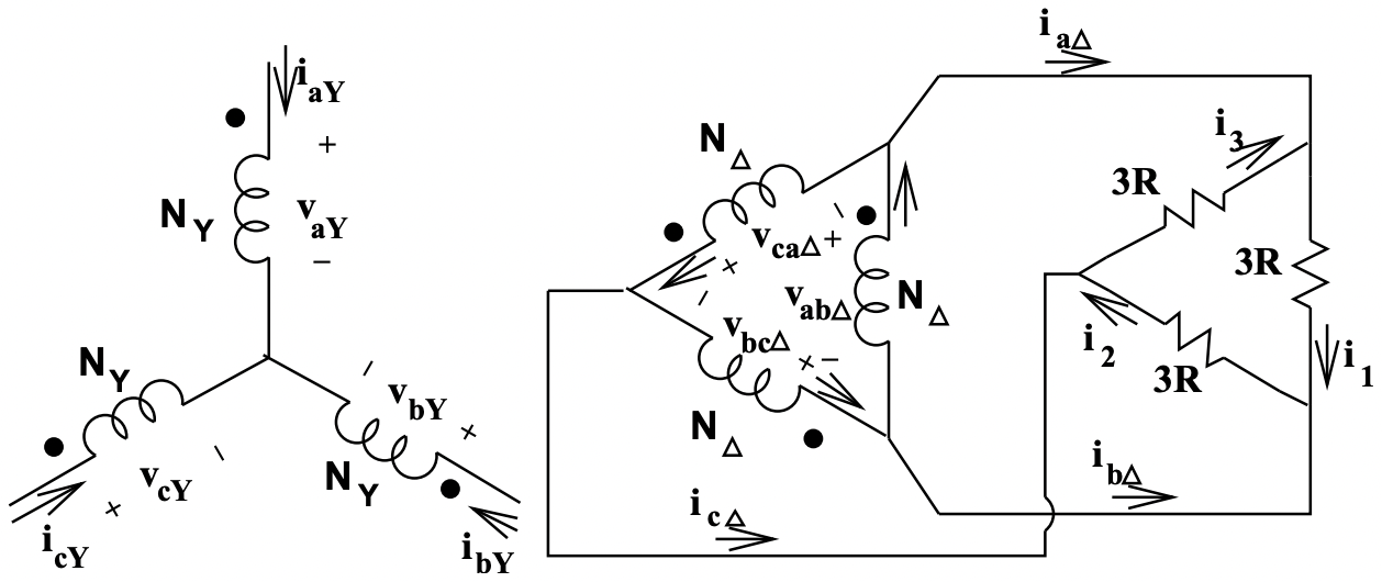 Figure 19: Equivalent Situation
Solving for currents in the legs of the transformer \(\ \Delta\), subtract, for example, the second expression from the first:
\(\ 2 i_{1 \Delta}-i_{2 \Delta}-i_{3 \Delta}=\frac{2 v_{a b \Delta}-v_{b c \Delta}-v_{c a \Delta}}{3 R}\)
Now, taking advantage of the fact that the system is balanced:
\(\ \begin{array}{r}
i_{1 \Delta}+i_{2 \Delta}+i_{3 \Delta}=0 \\
v_{a b \Delta}+v_{b c \Delta}+v_{c a \Delta}=0
\end{array}\)
to find:
\(\ \begin{array}{l}
i_{1 \Delta}=\frac{v_{a b \Delta}}{3 R} \\
i_{2 \Delta}=\frac{v_{b c \Delta}}{3 R} \\
i_{3 \Delta}=\frac{v_{c a \Delta}}{3 R}
\end{array}\)
Finally, the ideal transformer relations give:
\(\ \begin{array}{ll}
v_{a b \Delta}=\frac{N_{\Delta}}{N_{Y}} v_{a Y} & i_{a Y}=\frac{N_{\Delta}}{N_{Y}} i_{1 \Delta} \\
v_{b c \Delta}=\frac{N_{\Delta}}{N_{Y}} v_{b Y} & i_{b Y}=\frac{N_{\Delta}}{N_{Y}} i_{2 \Delta} \\
v_{c a \Delta}=\frac{N_{\Delta}}{N_{Y}} v_{c Y} & i_{c Y}=\frac{N_{\Delta}}{N_{Y}} i_{3 \Delta}
\end{array}\)
so that:
\(\ \begin{aligned}
i_{a Y}&=\left(\frac{N_{\Delta}}{N_{Y}}\right)^{2} \frac{1}{3 R} v_{a Y}\\
i_{b Y} &=\left(\frac{N_{\Delta}}{N_{Y}}\right)^{2} \frac{1}{3 R} v_{b Y} \\
i_{c Y} &=\left(\frac{N_{\Delta}}{N_{Y}}\right)^{2} \frac{1}{3 R} v_{c Y}
\end{aligned}\)
The apparent resistance (that is, apparent were it to be connected in \(\ wye\)) at the \(\ wye\) terminals of the transformer is:
\(\ R_{e q}=3 R\left(\frac{N_{Y}}{N_{\Delta}}\right)^{2}\)
Expressed in terms of voltage ratio, this is:
\(\ R_{e q}=3 R\left(\frac{N}{\sqrt{3}}\right)^{2}=R\left(\frac{v_{Y}}{v_{\Delta}}\right)^{2}\)
It is important to note that this solution took the long way around. Taken consistently (uniformly on a line-neutral or uniformly on a line-line basis), impedances transform across transformers by the square of the voltage ratio, no matter what connection is used.