
7.4: Return Loss, Substitution Loss, and Insertion Loss
- Page ID
- 41301

7.4.1 Return Loss
Return loss, also known as reflection loss, is a measure of the fraction of available power that is not delivered by a source to a load. If the power incident on a load is \(P_{i}\) and the power reflected by the load is \(P_{r}\), then the return loss in decibels is [1, 2]
\[\label{eq:1}\text{RL}_{\text{dB}}=10\log\frac{P_{i}}{P_{r}} \]
The better the load is matched to the source, the lower the reflected power and hence the higher the return loss. RL is a positive quantity if the reflected power is less than the incident power. If the load has a complex reflection coefficient \(\rho\), then
\[\label{eq:2}\text{RL}_{\text{dB}}=10\log\left|\frac{1}{\rho^{2}}\right|=-20\log |\rho| \]
That is, the return loss is the negative of the reflection coefficient expressed in decibels [3].
When generalized to terminated two ports, the return loss is defined with respect to the input reflection coefficient of a terminated two port [4]. The two port in Figure \(\PageIndex{1}\) has the input reflection coefficient
\[\label{eq:3}\Gamma_{\text{in}}=S_{11}+\frac{\Gamma_{L}S_{12}S_{21}}{(1-\Gamma_{L}S_{22})} \]
where \(\Gamma_{L}\) is the reflection coefficient of the load. Thus the return loss of a terminated two-port is
\[\label{eq:4}\text{RL}_{\text{dB}}=-20\log |\Gamma_{\text{in}}|=-20\log\left|S_{11}+\frac{\Gamma_{L}S_{12}S_{21}}{(1-\Gamma_{L}S_{22})}\right| \]
If the load is matched, i.e. \(Z_{L} = Z_{0}^{\ast}\) (the system reference impedance), then
\[\label{eq:5}\text{RL}_{\text{dB}}=-20\log |S_{11}| \]
This return loss is also called the input return loss since the reflection coefficient is calculated at Port 1. The output return loss is calculated looking into Port 2 of the two-port, where now the termination at Port 1 is just the source impedance.
7.4.2 Substitution Loss and Insertion Loss
The substitution loss is the ratio of the power, \(^{i}P_{L}\), delivered to the load by an initial two-port identified by the leading superscript ‘\(i\)’, and the power delivered to the load, \(^{f}P_{L}\), with a substituted final two-port identified by the leading superscript ‘\(f\)’. In terms of scattering parameters with reference impedances \(Z_{\text{REF}}\), the substitution loss in decibels is (using the results in [5] and noting that \(\Gamma_{S}\) and \(\Gamma_{L}\) are referred to \(Z_{\text{REF}}\))
\[\label{eq:6}L_{S}|{\text{dB}}=\frac{^{i}P_{L}}{^{f}P_{L}}=10\log\left|\frac{^{i}S_{21}}{^{f}S_{21}}\frac{[(1- ^{f}S_{11}\Gamma_{S})(1- ^{f}S_{22}\Gamma_{L})- ^{f}S_{12}\:^{f}S_{21}\Gamma_{S}\Gamma_{L}]}{[(1- ^{i}S_{11}\Gamma_{S})(1-^{i}S_{22}\Gamma_{L})-^{i}S_{12}\:^{i}S_{21}\Gamma_{S}\Gamma_{L}} \right|^{2} \]
Insertion loss is a special case of substitution loss with a particular type of initial two-port networks.
Insertion Loss with an Ideal Adaptor
Insertion loss is the substitution loss when the initial two-poort is a direct connection so \(^{i}S_{11} =0= ^{i}S_{22}\) (for no reflection), \(^{i}S_{12} ^{i}S_{21} = 1\) (for no loss in the adaptor and there is no phase shift), and \(^{i} S_{12} = ^{i} S_{21}\) (for reciprocity), insertion loss in decibels is, using Equation \(\eqref{eq:6}\):
\[\label{eq:7}\text{IL}|_{\text{dB}}=10\log\left[\left|\frac{(1- ^{f}S_{11}\Gamma_{S})(1- ^{f}S_{22}\Gamma_{L})- ^{f}S_{12} ^{f}S_{21}\Gamma_{S}\Gamma_{L}}{^{f}S_{12}(1-\Gamma_{S}\Gamma)}\right|^{2}\right] \]
Attenuation is defined as the insertion loss without source and load
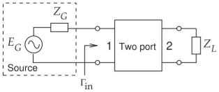
Figure \(\PageIndex{1}\): Terminated two-port used to define return loss.
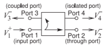
Figure \(\PageIndex{2}\): Schematic of a directional coupler.
reflections \((\Gamma_{S} =0= \Gamma_{L})\) [6], and Equation \(\eqref{eq:7}\) becomes
\[\label{eq:8}A|_{\text{dB}}=10\log\left(\frac{Z_{02}}{Z_{01}}\frac{1}{|S_{21}|^{2}}\right)\quad (=\text{ IL with }\Gamma_{S}=0=\Gamma_{L}) \]