Engineering LibreTexts

5.11: Quantum dot models of quantum wire transistor channels

  • Page ID
    51622
  • \( \newcommand{\vecs}[1]{\overset { \scriptstyle \rightharpoonup} {\mathbf{#1}} } \) \( \newcommand{\vecd}[1]{\overset{-\!-\!\rightharpoonup}{\vphantom{a}\smash {#1}}} \)\(\newcommand{\id}{\mathrm{id}}\) \( \newcommand{\Span}{\mathrm{span}}\) \( \newcommand{\kernel}{\mathrm{null}\,}\) \( \newcommand{\range}{\mathrm{range}\,}\) \( \newcommand{\RealPart}{\mathrm{Re}}\) \( \newcommand{\ImaginaryPart}{\mathrm{Im}}\) \( \newcommand{\Argument}{\mathrm{Arg}}\) \( \newcommand{\norm}[1]{\| #1 \|}\) \( \newcommand{\inner}[2]{\langle #1, #2 \rangle}\) \( \newcommand{\Span}{\mathrm{span}}\) \(\newcommand{\id}{\mathrm{id}}\) \( \newcommand{\Span}{\mathrm{span}}\) \( \newcommand{\kernel}{\mathrm{null}\,}\) \( \newcommand{\range}{\mathrm{range}\,}\) \( \newcommand{\RealPart}{\mathrm{Re}}\) \( \newcommand{\ImaginaryPart}{\mathrm{Im}}\) \( \newcommand{\Argument}{\mathrm{Arg}}\) \( \newcommand{\norm}[1]{\| #1 \|}\) \( \newcommand{\inner}[2]{\langle #1, #2 \rangle}\) \( \newcommand{\Span}{\mathrm{span}}\)\(\newcommand{\AA}{\unicode[.8,0]{x212B}}\)

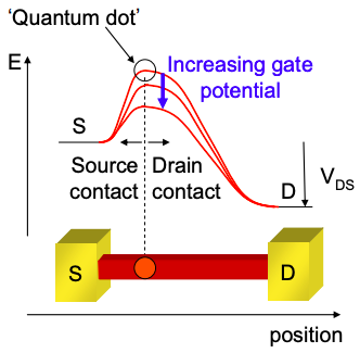
    Under bias we expect a spatial variation in the potential along a quantum wire. Current flow may also vary the charge density along the wire, which in turn affects the potential profile. Thus, the potential variation must be determined self consistently with the current flow.

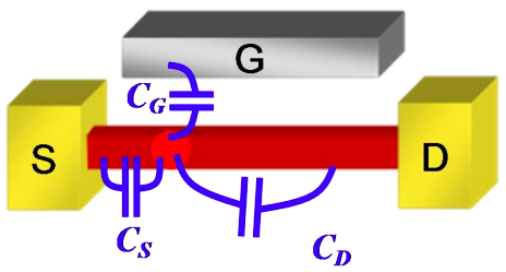
    We have seen in Part 4 that the conduction band edge in a ballistic conductor is determined by the point of maximum potential in the conductor. For electrostatic purposes, we will approximate this point on the quantum wire as a quantum dot, and then employ our discrete capacitive models of potential to calculate changes in the conduction band edge.

    Usually the highest potential is located next to the source, because application of forward bias at the drain pulls the potential down along the channel.

    Screenshot 2021-05-18 at 19.23.15.png
    Figure \(\PageIndex{1}\): An example of a typical potential profile along the length of a quantum wire as reflected by the bottom of the conduction band. The point of maximum potential acts as a barrier to the flow of current. As the gate bias increases, the barrier decreases, enhancing current flow. The point of maximum potential is modeled as a quantum dot with the same density of states as the quantum wire. The remainder of the wire is considered to be part of the contacts.
    Screenshot 2021-05-18 at 19.26.17.png
    Figure \(\PageIndex{2}\): Assuming the channel is modeled by a quantum dot we model the electrostatics of the transistor using capacitors.

    This page titled 5.11: Quantum dot models of quantum wire transistor channels is shared under a CC BY-NC-SA 4.0 license and was authored, remixed, and/or curated by Marc Baldo (MIT OpenCourseWare) via source content that was edited to the style and standards of the LibreTexts platform; a detailed edit history is available upon request.