
6.13: Matching
- Page ID
- 88585

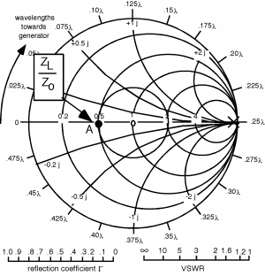
This gets us to "B", and we find that . Now this is a very interesting result.
Suppose we take the load off the line, and add, in series, an additional capacitor, whose reactance is .
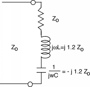
Figure \(\PageIndex{2}\): Matching the load with a capacitor
The capacitor and the inductor just cancel each other out (series resonance) and so the apparent load for the line is just , the magnitude of the reflection coefficient (Γ) = 0 and the ! All of the energy flowing down the line is coupled to the load resistor, and nothing is reflected back towards the load.
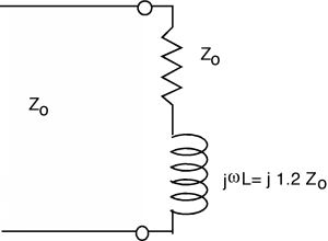
We were lucky that the real part of . If there were not that case, we would not be able to "match" the load to the line, right? Not completely. Let's consider another example. The next figure, Figure \(\PageIndex{3}\), shows a line with a , terminated with a resistor. , and we end up with the VSWR circle shown in the Figure \(\PageIndex{4}\).
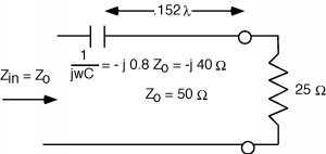
How could we match this load? We could add another \(25 \ \Omega\) in series with the first resistor, but if we want to maximize the power we deliver to the first one, this would not be a very satisfactory approach. Let's move down the line a ways. If we go to point "B", we find that at this spot, \(\frac{Z_{s}}{Z_{0}} = 1 + 0.8i\).
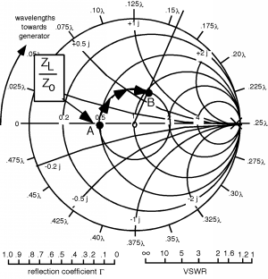
Once again, we have an impedance with a normalized real part equals 1! How far do we go? It looks like it's a little more than . If we add a negative reactance in series with the line at this point, with a normalized value of , then from that point on back to the generator, the line would "look" like it was terminated with a matched load.
There's one awkward feature to this solution, and that is we have to cut the line to insert the capacitor. It would be a lot easier if we could simply add something across the line, instead of having to cut it. This is easily done, if we go over into the admittance world.