
5.7: Resonators
- Page ID
- 41127
\( \newcommand{\vecs}[1]{\overset { \scriptstyle \rightharpoonup} {\mathbf{#1}} } \)
\( \newcommand{\vecd}[1]{\overset{-\!-\!\rightharpoonup}{\vphantom{a}\smash {#1}}} \)
\( \newcommand{\id}{\mathrm{id}}\) \( \newcommand{\Span}{\mathrm{span}}\)
( \newcommand{\kernel}{\mathrm{null}\,}\) \( \newcommand{\range}{\mathrm{range}\,}\)
\( \newcommand{\RealPart}{\mathrm{Re}}\) \( \newcommand{\ImaginaryPart}{\mathrm{Im}}\)
\( \newcommand{\Argument}{\mathrm{Arg}}\) \( \newcommand{\norm}[1]{\| #1 \|}\)
\( \newcommand{\inner}[2]{\langle #1, #2 \rangle}\)
\( \newcommand{\Span}{\mathrm{span}}\)
\( \newcommand{\id}{\mathrm{id}}\)
\( \newcommand{\Span}{\mathrm{span}}\)
\( \newcommand{\kernel}{\mathrm{null}\,}\)
\( \newcommand{\range}{\mathrm{range}\,}\)
\( \newcommand{\RealPart}{\mathrm{Re}}\)
\( \newcommand{\ImaginaryPart}{\mathrm{Im}}\)
\( \newcommand{\Argument}{\mathrm{Arg}}\)
\( \newcommand{\norm}[1]{\| #1 \|}\)
\( \newcommand{\inner}[2]{\langle #1, #2 \rangle}\)
\( \newcommand{\Span}{\mathrm{span}}\) \( \newcommand{\AA}{\unicode[.8,0]{x212B}}\)
\( \newcommand{\vectorA}[1]{\vec{#1}} % arrow\)
\( \newcommand{\vectorAt}[1]{\vec{\text{#1}}} % arrow\)
\( \newcommand{\vectorB}[1]{\overset { \scriptstyle \rightharpoonup} {\mathbf{#1}} } \)
\( \newcommand{\vectorC}[1]{\textbf{#1}} \)
\( \newcommand{\vectorD}[1]{\overrightarrow{#1}} \)
\( \newcommand{\vectorDt}[1]{\overrightarrow{\text{#1}}} \)
\( \newcommand{\vectE}[1]{\overset{-\!-\!\rightharpoonup}{\vphantom{a}\smash{\mathbf {#1}}}} \)
\( \newcommand{\vecs}[1]{\overset { \scriptstyle \rightharpoonup} {\mathbf{#1}} } \)
\( \newcommand{\vecd}[1]{\overset{-\!-\!\rightharpoonup}{\vphantom{a}\smash {#1}}} \)
\(\newcommand{\avec}{\mathbf a}\) \(\newcommand{\bvec}{\mathbf b}\) \(\newcommand{\cvec}{\mathbf c}\) \(\newcommand{\dvec}{\mathbf d}\) \(\newcommand{\dtil}{\widetilde{\mathbf d}}\) \(\newcommand{\evec}{\mathbf e}\) \(\newcommand{\fvec}{\mathbf f}\) \(\newcommand{\nvec}{\mathbf n}\) \(\newcommand{\pvec}{\mathbf p}\) \(\newcommand{\qvec}{\mathbf q}\) \(\newcommand{\svec}{\mathbf s}\) \(\newcommand{\tvec}{\mathbf t}\) \(\newcommand{\uvec}{\mathbf u}\) \(\newcommand{\vvec}{\mathbf v}\) \(\newcommand{\wvec}{\mathbf w}\) \(\newcommand{\xvec}{\mathbf x}\) \(\newcommand{\yvec}{\mathbf y}\) \(\newcommand{\zvec}{\mathbf z}\) \(\newcommand{\rvec}{\mathbf r}\) \(\newcommand{\mvec}{\mathbf m}\) \(\newcommand{\zerovec}{\mathbf 0}\) \(\newcommand{\onevec}{\mathbf 1}\) \(\newcommand{\real}{\mathbb R}\) \(\newcommand{\twovec}[2]{\left[\begin{array}{r}#1 \\ #2 \end{array}\right]}\) \(\newcommand{\ctwovec}[2]{\left[\begin{array}{c}#1 \\ #2 \end{array}\right]}\) \(\newcommand{\threevec}[3]{\left[\begin{array}{r}#1 \\ #2 \\ #3 \end{array}\right]}\) \(\newcommand{\cthreevec}[3]{\left[\begin{array}{c}#1 \\ #2 \\ #3 \end{array}\right]}\) \(\newcommand{\fourvec}[4]{\left[\begin{array}{r}#1 \\ #2 \\ #3 \\ #4 \end{array}\right]}\) \(\newcommand{\cfourvec}[4]{\left[\begin{array}{c}#1 \\ #2 \\ #3 \\ #4 \end{array}\right]}\) \(\newcommand{\fivevec}[5]{\left[\begin{array}{r}#1 \\ #2 \\ #3 \\ #4 \\ #5 \\ \end{array}\right]}\) \(\newcommand{\cfivevec}[5]{\left[\begin{array}{c}#1 \\ #2 \\ #3 \\ #4 \\ #5 \\ \end{array}\right]}\) \(\newcommand{\mattwo}[4]{\left[\begin{array}{rr}#1 \amp #2 \\ #3 \amp #4 \\ \end{array}\right]}\) \(\newcommand{\laspan}[1]{\text{Span}\{#1\}}\) \(\newcommand{\bcal}{\cal B}\) \(\newcommand{\ccal}{\cal C}\) \(\newcommand{\scal}{\cal S}\) \(\newcommand{\wcal}{\cal W}\) \(\newcommand{\ecal}{\cal E}\) \(\newcommand{\coords}[2]{\left\{#1\right\}_{#2}}\) \(\newcommand{\gray}[1]{\color{gray}{#1}}\) \(\newcommand{\lgray}[1]{\color{lightgray}{#1}}\) \(\newcommand{\rank}{\operatorname{rank}}\) \(\newcommand{\row}{\text{Row}}\) \(\newcommand{\col}{\text{Col}}\) \(\renewcommand{\row}{\text{Row}}\) \(\newcommand{\nul}{\text{Nul}}\) \(\newcommand{\var}{\text{Var}}\) \(\newcommand{\corr}{\text{corr}}\) \(\newcommand{\len}[1]{\left|#1\right|}\) \(\newcommand{\bbar}{\overline{\bvec}}\) \(\newcommand{\bhat}{\widehat{\bvec}}\) \(\newcommand{\bperp}{\bvec^\perp}\) \(\newcommand{\xhat}{\widehat{\xvec}}\) \(\newcommand{\vhat}{\widehat{\vvec}}\) \(\newcommand{\uhat}{\widehat{\uvec}}\) \(\newcommand{\what}{\widehat{\wvec}}\) \(\newcommand{\Sighat}{\widehat{\Sigma}}\) \(\newcommand{\lt}{<}\) \(\newcommand{\gt}{>}\) \(\newcommand{\amp}{&}\) \(\definecolor{fillinmathshade}{gray}{0.9}\)Near resonance, the response of a microwave resonator is very similar to the resonance response of a parallel or series \(LC\) resonant circuit, shown in Figure \(\PageIndex{1}\)(e and f). These equivalent circuits can be used over a narrow frequency range of perhaps \(5\%\) fractional bandwidth.
Several types of resonators are shown in Figure \(\PageIndex{1}\). Figure \(\PageIndex{1}\)(a) is a rectangular cavity resonator coupled to an external coaxial line by a small coupling loop. Figure \(\PageIndex{1}\)(b) is a microstrip patch reflection resonator. This resonator has large coupling to the external circuit. The coupling can be reduced and photolithographically controlled by introducing a gap, as shown in Figure \(\PageIndex{1}\)(c), to create what is called a microstrip gap-coupled transmission line reflection resonator. The \(Q\) of a resonator can be dramatically increased by using a low-loss, high-dielectric constant material, as shown in Figure \(\PageIndex{1}\)(d), for a dielectric transmission resonator in microstrip.
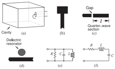
Figure \(\PageIndex{1}\): Microwave resonators: (a) rectangular cavity resonator, (b) microstrip patch resonator (c) microstrip gap-coupled reflection resonator, (d) dielectric transmission resonator in microstrip, (e) parallel equivalent circuits, and (f) series equivalent circuits.
5.7.1 Dielectric Resonators
Any dielectric structure can store EM energy, with the resonant frequency dependent on both the permittivity and the physical dimensions. At the resonance frequency, all resonators store the maximum amount of energy. Two resonators that store particularly large amounts of energy are the cavity resonator shown in Figure \(\PageIndex{1}\)(a) and the dielectric resonator shown in Figure \(\PageIndex{1}\)(d).
Microwave ceramics can have very low loss and high permittivity (which results in small wavelengths and hence small size) and are commonly used in microwave resonators. Low-loss ceramic materials with permittivities in the range of \(21\) to \(150\) are generally available and unloaded \(Q\) factors are in the \(5,000\) to \(10,000\) range. Physical dimensions generally depend upon the resonant frequencies desired.
The general theoretical expression for the resonant frequencies, applying to a cylindrical dielectric resonator of radius \(a\) and height \(d\), is
\[\label{eq:1}f_{mnl}=\frac{c}{2\sqrt{\varepsilon_{r}}}\sqrt{\left(\frac{χ_{mn}}{\pi a}\right)^{2}+\left(\frac{l}{d}\right)^{2}} \]
where the integer \(l\) denotes the number of half wavelengths in the vertical direction and \(χ_{mn}\) is the \(m\)th extremum of the Bessel function \(J_{n}\) for a TM mode (or alternatively the \(m\)th zero for a TE mode).
Figure \(\PageIndex{1}\)(d) shows a common use of a dielectric resonator, often called a puck, coupling to the fields of a microstrip line. The puck has a resonance defined by the radius of the high permittivity puck. There can be several modes of resonance, with some modes introducing a parallel resonant circuit (Figure \(\PageIndex{1}\)(e)) in shunt across the line and others introducing a series resonant circuit in shunt across the line (Figure \(\PageIndex{1}\)(f)).