4.6: Microstrip Operating Frequency Limitations
- Page ID
- 41041
\( \newcommand{\vecs}[1]{\overset { \scriptstyle \rightharpoonup} {\mathbf{#1}} } \)
\( \newcommand{\vecd}[1]{\overset{-\!-\!\rightharpoonup}{\vphantom{a}\smash {#1}}} \)
\( \newcommand{\id}{\mathrm{id}}\) \( \newcommand{\Span}{\mathrm{span}}\)
( \newcommand{\kernel}{\mathrm{null}\,}\) \( \newcommand{\range}{\mathrm{range}\,}\)
\( \newcommand{\RealPart}{\mathrm{Re}}\) \( \newcommand{\ImaginaryPart}{\mathrm{Im}}\)
\( \newcommand{\Argument}{\mathrm{Arg}}\) \( \newcommand{\norm}[1]{\| #1 \|}\)
\( \newcommand{\inner}[2]{\langle #1, #2 \rangle}\)
\( \newcommand{\Span}{\mathrm{span}}\)
\( \newcommand{\id}{\mathrm{id}}\)
\( \newcommand{\Span}{\mathrm{span}}\)
\( \newcommand{\kernel}{\mathrm{null}\,}\)
\( \newcommand{\range}{\mathrm{range}\,}\)
\( \newcommand{\RealPart}{\mathrm{Re}}\)
\( \newcommand{\ImaginaryPart}{\mathrm{Im}}\)
\( \newcommand{\Argument}{\mathrm{Arg}}\)
\( \newcommand{\norm}[1]{\| #1 \|}\)
\( \newcommand{\inner}[2]{\langle #1, #2 \rangle}\)
\( \newcommand{\Span}{\mathrm{span}}\) \( \newcommand{\AA}{\unicode[.8,0]{x212B}}\)
\( \newcommand{\vectorA}[1]{\vec{#1}} % arrow\)
\( \newcommand{\vectorAt}[1]{\vec{\text{#1}}} % arrow\)
\( \newcommand{\vectorB}[1]{\overset { \scriptstyle \rightharpoonup} {\mathbf{#1}} } \)
\( \newcommand{\vectorC}[1]{\textbf{#1}} \)
\( \newcommand{\vectorD}[1]{\overrightarrow{#1}} \)
\( \newcommand{\vectorDt}[1]{\overrightarrow{\text{#1}}} \)
\( \newcommand{\vectE}[1]{\overset{-\!-\!\rightharpoonup}{\vphantom{a}\smash{\mathbf {#1}}}} \)
\( \newcommand{\vecs}[1]{\overset { \scriptstyle \rightharpoonup} {\mathbf{#1}} } \)
\( \newcommand{\vecd}[1]{\overset{-\!-\!\rightharpoonup}{\vphantom{a}\smash {#1}}} \)
\(\newcommand{\avec}{\mathbf a}\) \(\newcommand{\bvec}{\mathbf b}\) \(\newcommand{\cvec}{\mathbf c}\) \(\newcommand{\dvec}{\mathbf d}\) \(\newcommand{\dtil}{\widetilde{\mathbf d}}\) \(\newcommand{\evec}{\mathbf e}\) \(\newcommand{\fvec}{\mathbf f}\) \(\newcommand{\nvec}{\mathbf n}\) \(\newcommand{\pvec}{\mathbf p}\) \(\newcommand{\qvec}{\mathbf q}\) \(\newcommand{\svec}{\mathbf s}\) \(\newcommand{\tvec}{\mathbf t}\) \(\newcommand{\uvec}{\mathbf u}\) \(\newcommand{\vvec}{\mathbf v}\) \(\newcommand{\wvec}{\mathbf w}\) \(\newcommand{\xvec}{\mathbf x}\) \(\newcommand{\yvec}{\mathbf y}\) \(\newcommand{\zvec}{\mathbf z}\) \(\newcommand{\rvec}{\mathbf r}\) \(\newcommand{\mvec}{\mathbf m}\) \(\newcommand{\zerovec}{\mathbf 0}\) \(\newcommand{\onevec}{\mathbf 1}\) \(\newcommand{\real}{\mathbb R}\) \(\newcommand{\twovec}[2]{\left[\begin{array}{r}#1 \\ #2 \end{array}\right]}\) \(\newcommand{\ctwovec}[2]{\left[\begin{array}{c}#1 \\ #2 \end{array}\right]}\) \(\newcommand{\threevec}[3]{\left[\begin{array}{r}#1 \\ #2 \\ #3 \end{array}\right]}\) \(\newcommand{\cthreevec}[3]{\left[\begin{array}{c}#1 \\ #2 \\ #3 \end{array}\right]}\) \(\newcommand{\fourvec}[4]{\left[\begin{array}{r}#1 \\ #2 \\ #3 \\ #4 \end{array}\right]}\) \(\newcommand{\cfourvec}[4]{\left[\begin{array}{c}#1 \\ #2 \\ #3 \\ #4 \end{array}\right]}\) \(\newcommand{\fivevec}[5]{\left[\begin{array}{r}#1 \\ #2 \\ #3 \\ #4 \\ #5 \\ \end{array}\right]}\) \(\newcommand{\cfivevec}[5]{\left[\begin{array}{c}#1 \\ #2 \\ #3 \\ #4 \\ #5 \\ \end{array}\right]}\) \(\newcommand{\mattwo}[4]{\left[\begin{array}{rr}#1 \amp #2 \\ #3 \amp #4 \\ \end{array}\right]}\) \(\newcommand{\laspan}[1]{\text{Span}\{#1\}}\) \(\newcommand{\bcal}{\cal B}\) \(\newcommand{\ccal}{\cal C}\) \(\newcommand{\scal}{\cal S}\) \(\newcommand{\wcal}{\cal W}\) \(\newcommand{\ecal}{\cal E}\) \(\newcommand{\coords}[2]{\left\{#1\right\}_{#2}}\) \(\newcommand{\gray}[1]{\color{gray}{#1}}\) \(\newcommand{\lgray}[1]{\color{lightgray}{#1}}\) \(\newcommand{\rank}{\operatorname{rank}}\) \(\newcommand{\row}{\text{Row}}\) \(\newcommand{\col}{\text{Col}}\) \(\renewcommand{\row}{\text{Row}}\) \(\newcommand{\nul}{\text{Nul}}\) \(\newcommand{\var}{\text{Var}}\) \(\newcommand{\corr}{\text{corr}}\) \(\newcommand{\len}[1]{\left|#1\right|}\) \(\newcommand{\bbar}{\overline{\bvec}}\) \(\newcommand{\bhat}{\widehat{\bvec}}\) \(\newcommand{\bperp}{\bvec^\perp}\) \(\newcommand{\xhat}{\widehat{\xvec}}\) \(\newcommand{\vhat}{\widehat{\vvec}}\) \(\newcommand{\uhat}{\widehat{\uvec}}\) \(\newcommand{\what}{\widehat{\wvec}}\) \(\newcommand{\Sighat}{\widehat{\Sigma}}\) \(\newcommand{\lt}{<}\) \(\newcommand{\gt}{>}\) \(\newcommand{\amp}{&}\) \(\definecolor{fillinmathshade}{gray}{0.9}\)Different types of higher-order modes can exist with microstrip and the two maximum operating frequencies of microstrip lines are (a) the lowest-order TM mode and (b) the lowest-order transverse microstrip resonance mode. In practice, multimoding is a problem when two conditions are met. First it must be possible for higher-order field variations to exist, and second, that energy can be effectively coupled into the higher-order mode. Generally this

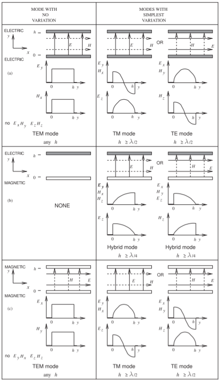
Figure \(\PageIndex{1}\): Lowest-order modes supported by combinations of electric and magnetic walls.
requires significant discontinuity on the line or that the phase velocities of two modes approximately coincide. An early discussion said that the phase velocities of two modes would be different and this is when the dielectric is uniform. However, with a nonhomogeneous line like microstrip, there can be frequencies where the phase velocities of two modes can coincide.
Since discontinuities are inevitable it is always a good idea to use only the first consideration. As was noted previously, the modal analysis that was possible with the parallel-plate waveguide cannot be repeated easily for the microstrip line because of the irregular cross section, but the phenomena is very similar. Instead of a TEM mode, there is a quasi-TEM mode and there are TE and TM modes.
4.6.1 Microstrip Dielectric Mode (Slab Mode)
A dielectric on a ground plane with an air region (of a wavelength or more above it) can support a TM mode, generally called a microstrip dielectric mode, substrate mode, microstrip TM mode, or slab mode. The microstrip dielectric mode is a problem for narrow microstrip lines. Whether this mode exists in a microstrip environment depends on whether energy can be coupled from the quasi-TEM mode (which is always generated) of the microstrip line into the TM dielectric mode. The critical frequency at which the TM mode becomes important is when there is significant coupling. Coupling is a problem with a microstrip line having a narrow strip, as the field orientations of the quasi-TEM mode and the dielectric mode align. Also, coupling occurs when the phase velocities of the two modes coincide. A detailed analysis reported in Chapter 11 of [12] and in [13] shows that this occurs at the first critical frequency,
\[\label{eq:1}f_{c1}=\frac{c\tan^{-1}(\varepsilon_{r})}{\sqrt{2}\pi h\sqrt{\varepsilon_{r}-1}} \]
At \(f_{c1}\) the dielectric mode will be generated even if there is not a discontinuity. If there is a discontinuity, say a split of one microstrip line into two microstrip lines, multimoding will occur when the dielectric mode can exist. From Figure \(\PageIndex{1}\)(b), the dielectric slab mode can be supported when \(h > \lambda_{g}/4\), where \(\lambda_{g}\) is the wavelength in the dielectric. Now \(\lambda_{g} =\lambda_{0}/\sqrt{\varepsilon_{r}}= c/(f\sqrt{\varepsilon_{r}})\), so the second critical frequency is
\[\label{eq:2}f_{c2}=\frac{c}{4h\sqrt{\varepsilon_{r}}} \]
This development assumes that the interface between the dielectric and air forms a good magnetic wall. With a dielectric having a permittivity of \(10\), typical for microwave circuits, the effective value of \(h\) would be increased by up to \(10\%\). However, it is difficult to place an exact value on this.
In summary, \(f_{c2}\) is the lowest frequency at which the dielectric mode will exist if there is a discontinuity, and \(f_{c1}\) is the lowest frequency at which the dielectric mode will exist if there is not a discontinuity.
The strip of a microstrip has a width of \(1\text{ mm}\) and is fabricated on a lossless substrate that is \(2.5\text{ mm}\) thick and has a relative permittivity of \(9\). At what frequency does the substrate (or slab) mode first occur?

Figure \(\PageIndex{2}\)
Solution
Two frequencies must be considered. One that comes from the dimensions of the dielectric slab and the other from considerations of matching phase velocities. From phase velocity consideration used in developing Equation \(\eqref{eq:1}\), the first critical frequency is
\[f_{c1}=\frac{c\tan^{-1}(\varepsilon_{r})}{\sqrt{2}\pi h\sqrt{\varepsilon_{r}-1}}=13.9\text{ GHz}\nonumber \]
The other critical frequency is when a variation of the magnetic or electric field can be supported between the ground plane and the approximate magnetic wall supported by the dielectric/free-space interface. This is when \(h =\frac{1}{4}\lambda =\lambda_{0}/(4\sqrt{9}) = 2.5\text{ mm} ⇒ \lambda_{0} = 3\text{ cm}\). Thus the second slab mode critical frequency is
\[f_{c2}=10\text{ GHz}\nonumber \]
Since discontinuities cannot be avoided, \(f_{c2}\) is the critical frequency to use.
4.6.2 Higher-Order Microstrip Mode
If the cross-sectional dimensions of a microstrip line are smaller than a fraction of a wavelength, then the electric and magnetic field lines will be as shown in Figure 3.1.2. These field lines have the minimum possible spatial variation and the fields are almost entirely confined to the transverse plane; this mode is called the quasi-TEM microstrip mode. However, as the frequency of the signal on the line increases it is possible for these fields to have one-quarter or one-half sinusoidal variations. Deriving the frequency at which a higher-order microstrip mode is supported is involved.
The following is a summary of a more complete discussion on operating frequency limitations in Section 7.8 of [12]. Some variations of the fields or modes do not look anything like the field orientations shown in Figure 3.1.2. However, the variations that are closest to the quasi-TEM mode are called higher-order microstrip modes and the one that occurs at the lowest frequency corresponds to a half-sinusoidal variation of the electric field between the edge of the strip and the ground plane. This path is a little longer than the path directly from the strip to the ground plane. However, for a wide strip, most of the EM energy is between the strip and the ground plane (both of which are electric walls) with approximate magnetic walls on the side of the strip. The modes are then similar to the parallel-plate waveguide modes described in Section 1.5. The next highest microstrip mode (or parallel-plate TE mode) occurs when there can be a half-sinusoidal variation of the electric field between the strip and the ground plane. This corresponds to Figure \(\PageIndex{1}\)(a). However, for finite-width strips the first higher-order microstrip mode occurs at a lower frequency than implied by the parallel-plate waveguide model. This is because the microstrip fields are not solely confined to the dielectric region, and in fact the electric field lines do not follow the shortest distance between the strip and the ground plane. Thus the fields along the longer paths to the sides of the strip can vary at a lower frequency than on the direct path. With detailed EM modeling and with experimental support it has been established that the first higher-order microstrip mode can exist at frequencies greater than [12]
\[\label{eq:3}f_{\text{Higher-Microstrip}}=\frac{c}{4h\sqrt{\varepsilon_{r}-1}} \]
This is, however, only an approximate guide.
The strip of a microstrip has a width of \(1\text{ mm}\) and is fabricated on a lossless substrate that is \(2.5\text{ mm}\) thick and has a relative permittivity of \(9\). At what frequency does the first higher microstrip mode first propagate?

Figure \(\PageIndex{3}\)

Figure \(\PageIndex{4}\)
Solution
The higher-order microstrip mode occurs when a half-wavelength variation of the electric field between the strip and the ground plane can be supported. When \(h = \lambda/2 = \lambda_{0}/(3\cdot 2) = 2.5\text{ mm}\); that is, the mode will occur when \(\lambda_{0} = 15\text{ mm}\). So
\[f_{\text{Higher-Microstrip}}=20\text{ GHz}\nonumber \]
A better estimate of the frequency where the higher-order microstrip mode becomes a problem is given by Equation \(\eqref{eq:3}\):
\[f_{\text{Higher-Microstrip}}=c/(4h\sqrt{\varepsilon_{r}-1})=10.6\text{ GHz}\nonumber \]
So two estimates have been calculated for the frequency at which the first higher-order microstrip mode can first exist. The first estimate is approximate and is based on a half-wavelength variation of the electric field confined to the direct path between the strip and the ground plane. The second estimate is more accurate as it considers that on the edge of the strip the fields follow a longer path to the ground plane. It is the half-wavelength variation on this longer path that determines if the higher-order microstrip mode will exist. Thus the more precise determination yields a lower critical frequency.
4.6.3 Transverse Microstrip Resonance
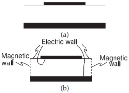
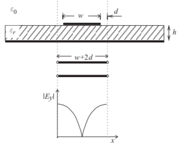
For a wide microstrip line, a transverse resonance mode can exist. This is the mode that occurs when EM energy bounces between the edges of the strip with the discontinuity at the strip edges forming a weak boundary. This is illustrated in Figure \(\PageIndex{5}\), where the microstrip shown in cross section in Figure \(\PageIndex{5}\)(a) is approximated as a rectangular waveguide in Figure \(\PageIndex{5}\)(b) with magnetic walls on the sides and an extended electrical wall on the top surface of the dielectric. Figure \(\PageIndex{5}\)(b) is called the microstrip waveguide model. The transverse resonance mode corresponds to the lowest-order \(H\) field variation between the magnetic walls. At the cutoff frequency for this transverse-resonant mode, the equivalent circuit is a resonant transmission line of length \(w + 2d\), as shown in Figure \(\PageIndex{6}\), where \(d = 0.2h\) accounts for the microstrip side fringing. A half-wavelength must be supported by the length \(w + 2d\). Therefore the cutoff half-wavelength is
\[\label{eq:4}\frac{\lambda_{c}}{2}=w+2d=w+0.4h\quad\text{that is}\quad\frac{c}{2f_{c}\sqrt{\varepsilon_{r}}}=w+0.4h \]
Hence the critical frequency for transverse resonance is
\[\label{eq:5}f_{c,\text{ TRAN}}=\frac{c}{\sqrt{\varepsilon_{r}}(2w+0.8h)} \]

Figure \(\PageIndex{5}\): Approximation of a microstrip line as a waveguide: (a) cross section of microstrip; and (b) microstrip waveguide model having effective width \(w + 0.4h\) with magnetic and electric walls.

Figure \(\PageIndex{6}\): Transverse resonance: standing wave (\(|E_{y}|\)) and equivalent transmission line of length \(w + 2d\), where \(d = 0.2h\).
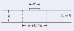
The strip of a microstrip has a width of \(1\text{ mm}\) and is fabricated on a lossless substrate that is \(2.5\text{ mm}\) thick and has a relative permittivity of \(9\).
- At what frequency does the transverse resonance first occur?
- What is the operating frequency range of the microstrip line?

Figure \(\PageIndex{7}\)
Solution
\(h = 2.5\text{ mm},\: w = 1\text{ mm},\:\lambda =\lambda_{0}/\sqrt{\varepsilon_{r}}= \lambda_{0}/3\)
- The magnetic waveguide model of Figure \(\PageIndex{5}\) can be used in estimating the frequency at which this occurs. The frequency at which the first transverse resonance mode occurs is when there is a full half-wavelength variation of the magnetic field between the magnetic walls, that is, when \(w + 0.4h = \lambda/2=2\text{ mm}\):
\[\label{eq:6}\frac{\lambda_{0}}{3\cdot 2}=2\text{ mm}⇒\lambda_{0}=12\text{ mm}\quad\text{and so}\quad f_{c,\text{ TRAN}}=25\text{ GHz} \] - All of the critical multimoding frequencies must be considered here and the minimum taken: for the slab mode, \(f_{c1}\) (Equation \(\eqref{eq:1}\)) and \(f_{c2}\) (Equation \(\eqref{eq:1}\), see Example \(\PageIndex{1}\) for the calculation of these); for the higher-order microstrip mode, fHigh−Microstrip (Equation \(\eqref{eq:3}\), see Example \(\PageIndex{2}\) for this calculation)); and for the transverse resonance mode (Equation \(\eqref{eq:6}\), and calculated in this example). So the operating frequency range is DC to \(10\text{ GHz}\).
4.6.4 Summary
There are four principal higher-order modes that need to be considered with microstrip transmission lines:
| Mode | Critical Frequency |
|---|---|
| Dielectric (or substrate) mode with no discontinuity | Equation \(\eqref{eq:1}\) |
| Dielectric (or substrate) mode with discontinuity | Equation \(\eqref{eq:2}\) |
| Higher order microstrip mode | Equation \(\eqref{eq:3}\) |
| Transverse resonance mode | Equation \(\eqref{eq:5}\) |
Table \(\PageIndex{1}\)
The lowest frequency determines the upper frequency of transmission line operation with a single mode.


