Engineering LibreTexts

3.1: Introduction

  • Page ID
    41187
  • \( \newcommand{\vecs}[1]{\overset { \scriptstyle \rightharpoonup} {\mathbf{#1}} } \)

    \( \newcommand{\vecd}[1]{\overset{-\!-\!\rightharpoonup}{\vphantom{a}\smash {#1}}} \)

    \( \newcommand{\id}{\mathrm{id}}\) \( \newcommand{\Span}{\mathrm{span}}\)

    ( \newcommand{\kernel}{\mathrm{null}\,}\) \( \newcommand{\range}{\mathrm{range}\,}\)

    \( \newcommand{\RealPart}{\mathrm{Re}}\) \( \newcommand{\ImaginaryPart}{\mathrm{Im}}\)

    \( \newcommand{\Argument}{\mathrm{Arg}}\) \( \newcommand{\norm}[1]{\| #1 \|}\)

    \( \newcommand{\inner}[2]{\langle #1, #2 \rangle}\)

    \( \newcommand{\Span}{\mathrm{span}}\)

    \( \newcommand{\id}{\mathrm{id}}\)

    \( \newcommand{\Span}{\mathrm{span}}\)

    \( \newcommand{\kernel}{\mathrm{null}\,}\)

    \( \newcommand{\range}{\mathrm{range}\,}\)

    \( \newcommand{\RealPart}{\mathrm{Re}}\)

    \( \newcommand{\ImaginaryPart}{\mathrm{Im}}\)

    \( \newcommand{\Argument}{\mathrm{Arg}}\)

    \( \newcommand{\norm}[1]{\| #1 \|}\)

    \( \newcommand{\inner}[2]{\langle #1, #2 \rangle}\)

    \( \newcommand{\Span}{\mathrm{span}}\) \( \newcommand{\AA}{\unicode[.8,0]{x212B}}\)

    \( \newcommand{\vectorA}[1]{\vec{#1}}      % arrow\)

    \( \newcommand{\vectorAt}[1]{\vec{\text{#1}}}      % arrow\)

    \( \newcommand{\vectorB}[1]{\overset { \scriptstyle \rightharpoonup} {\mathbf{#1}} } \)

    \( \newcommand{\vectorC}[1]{\textbf{#1}} \)

    \( \newcommand{\vectorD}[1]{\overrightarrow{#1}} \)

    \( \newcommand{\vectorDt}[1]{\overrightarrow{\text{#1}}} \)

    \( \newcommand{\vectE}[1]{\overset{-\!-\!\rightharpoonup}{\vphantom{a}\smash{\mathbf {#1}}}} \)

    \( \newcommand{\vecs}[1]{\overset { \scriptstyle \rightharpoonup} {\mathbf{#1}} } \)

    \( \newcommand{\vecd}[1]{\overset{-\!-\!\rightharpoonup}{\vphantom{a}\smash {#1}}} \)

    \(\newcommand{\avec}{\mathbf a}\) \(\newcommand{\bvec}{\mathbf b}\) \(\newcommand{\cvec}{\mathbf c}\) \(\newcommand{\dvec}{\mathbf d}\) \(\newcommand{\dtil}{\widetilde{\mathbf d}}\) \(\newcommand{\evec}{\mathbf e}\) \(\newcommand{\fvec}{\mathbf f}\) \(\newcommand{\nvec}{\mathbf n}\) \(\newcommand{\pvec}{\mathbf p}\) \(\newcommand{\qvec}{\mathbf q}\) \(\newcommand{\svec}{\mathbf s}\) \(\newcommand{\tvec}{\mathbf t}\) \(\newcommand{\uvec}{\mathbf u}\) \(\newcommand{\vvec}{\mathbf v}\) \(\newcommand{\wvec}{\mathbf w}\) \(\newcommand{\xvec}{\mathbf x}\) \(\newcommand{\yvec}{\mathbf y}\) \(\newcommand{\zvec}{\mathbf z}\) \(\newcommand{\rvec}{\mathbf r}\) \(\newcommand{\mvec}{\mathbf m}\) \(\newcommand{\zerovec}{\mathbf 0}\) \(\newcommand{\onevec}{\mathbf 1}\) \(\newcommand{\real}{\mathbb R}\) \(\newcommand{\twovec}[2]{\left[\begin{array}{r}#1 \\ #2 \end{array}\right]}\) \(\newcommand{\ctwovec}[2]{\left[\begin{array}{c}#1 \\ #2 \end{array}\right]}\) \(\newcommand{\threevec}[3]{\left[\begin{array}{r}#1 \\ #2 \\ #3 \end{array}\right]}\) \(\newcommand{\cthreevec}[3]{\left[\begin{array}{c}#1 \\ #2 \\ #3 \end{array}\right]}\) \(\newcommand{\fourvec}[4]{\left[\begin{array}{r}#1 \\ #2 \\ #3 \\ #4 \end{array}\right]}\) \(\newcommand{\cfourvec}[4]{\left[\begin{array}{c}#1 \\ #2 \\ #3 \\ #4 \end{array}\right]}\) \(\newcommand{\fivevec}[5]{\left[\begin{array}{r}#1 \\ #2 \\ #3 \\ #4 \\ #5 \\ \end{array}\right]}\) \(\newcommand{\cfivevec}[5]{\left[\begin{array}{c}#1 \\ #2 \\ #3 \\ #4 \\ #5 \\ \end{array}\right]}\) \(\newcommand{\mattwo}[4]{\left[\begin{array}{rr}#1 \amp #2 \\ #3 \amp #4 \\ \end{array}\right]}\) \(\newcommand{\laspan}[1]{\text{Span}\{#1\}}\) \(\newcommand{\bcal}{\cal B}\) \(\newcommand{\ccal}{\cal C}\) \(\newcommand{\scal}{\cal S}\) \(\newcommand{\wcal}{\cal W}\) \(\newcommand{\ecal}{\cal E}\) \(\newcommand{\coords}[2]{\left\{#1\right\}_{#2}}\) \(\newcommand{\gray}[1]{\color{gray}{#1}}\) \(\newcommand{\lgray}[1]{\color{lightgray}{#1}}\) \(\newcommand{\rank}{\operatorname{rank}}\) \(\newcommand{\row}{\text{Row}}\) \(\newcommand{\col}{\text{Col}}\) \(\renewcommand{\row}{\text{Row}}\) \(\newcommand{\nul}{\text{Nul}}\) \(\newcommand{\var}{\text{Var}}\) \(\newcommand{\corr}{\text{corr}}\) \(\newcommand{\len}[1]{\left|#1\right|}\) \(\newcommand{\bbar}{\overline{\bvec}}\) \(\newcommand{\bhat}{\widehat{\bvec}}\) \(\newcommand{\bperp}{\bvec^\perp}\) \(\newcommand{\xhat}{\widehat{\xvec}}\) \(\newcommand{\vhat}{\widehat{\vvec}}\) \(\newcommand{\uhat}{\widehat{\uvec}}\) \(\newcommand{\what}{\widehat{\wvec}}\) \(\newcommand{\Sighat}{\widehat{\Sigma}}\) \(\newcommand{\lt}{<}\) \(\newcommand{\gt}{>}\) \(\newcommand{\amp}{&}\) \(\definecolor{fillinmathshade}{gray}{0.9}\)

    An essential function of a radio transmitter is modulation which is implemented by a modulator which converts the information at baseband to a finite bandwidth modulated radio signal centered at or near the carrier frequency. At the block level a modulator is described by its architecture and at a lower level by its circuit implementation. In a receiver a demodulator demodulates the radio signal extracting the baseband information.

    The architectures of transmitters and receivers have changed significantly since the first radio signals were transmitted. Largely this is the result of increased integration of hardware but also due to advances in modulation concepts. In modern radios, as used with 4G and 5G cellular radio, many of the modulation functions once only implemented with analog hardware are now implemented digitally in a digital signal processing (DSP) unit. Only the final translation to the frequency of the radio signal is implemented in analog hardware. This concept is known as software-defined radio (SDR) which also has the additional implication that the analog hardware can be reconfigured under software control. SDR has two significant impacts.
    clipboard_e423d0b24ec8c18ed8bb5f190331c4beb.png

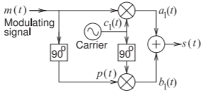
    Figure \(\PageIndex{1}\): Hartley modulator implementing singlesideband suppressed-carrier (SSB-SC) modulation. The “\(90^{\circ}\)” blocks shift the phase of the signal by \(+90^{\circ}\). The mixer indicated by the circle with a cross is an ideal multiplier, e.g. \(a_{1}(t) = m(t)\cdot c_{1}(t)\).

    One is that it is feasible to support a large number of modulation schemes including legacy modulation schemes, without any changes to the analog hardware. The second is that by simplifying the functionality of the analog hardware it is possible to optimize analog hardware for maximum efficiency. Demodulation has also been significantly impacted by SDR with a similar transfer of functions from analog to digital hardware.

    In some designs a receiver and a transmitter share components and then the RF front end is called a transceiver. This chapter is concerned with the architectures of receivers, transmitters, and transceivers. Design choices are made to maximize the tolerance to interference, manage hardware complexity, optimize power efficiency, and enable various radios to simultaneously operate together.

    The presentation in this chapter closely follows the historical development of transmitters and receivers. As well, modulators and demodulators at different stages of evolution are considered together.

    Section 3.2 introduces single-sideband and double-sideband modulation. Then early modulator and demodulator technology is considered in Section 3.3. These were circuits that could be implemented with just a few vacuum tubes or transistors and, in one case, a demodulator could be implemented with a single diode. With increasing circuit sophistication an architectural approach to modulator and demodulator design became possible. These are considered in Section 3.4. Demodulation requires local generation of a radio signal’s carrier in a process called carrier recovery. This is discussed in Section 3.5. Following this is a discussion of more modern transmitters and receivers as used in 2G and 3G cellular radio in Sections 3.6 and 3.7 respectively. Current radios, e.g. 4G and 5G, are software defined radios (SDRs) where most of the modulation and demodulation is implemented in DSP and there is considerable software-based adaptation of the analog hardware that now undertakes the task of translating between and low intermediate frequency and the frequency of the radio signal. Sections 3.8– 3.13 present the many aspects of SDR transmitters and receivers.


    This page titled 3.1: Introduction is shared under a CC BY-NC license and was authored, remixed, and/or curated by Michael Steer.

    • Was this article helpful?