
4.9: MMIC Power Amplifiers
- Page ID
- 46077
A linear Class A X-band amplifier implemented in GaAs MESFET microwave monolithic integrated circuit (MMIC) technology is shown in Figure \(\PageIndex{1}\). This amplifier operates from \(8\) to \(12\text{ GHz}\) producing \(100\text{ mW}\) of total power. This is a two-stage amplifier, as this results in the required gain, power, and bandwidth. The input and output pads are in a ground-signal-ground (GSG) configuration and can be used for both microwave
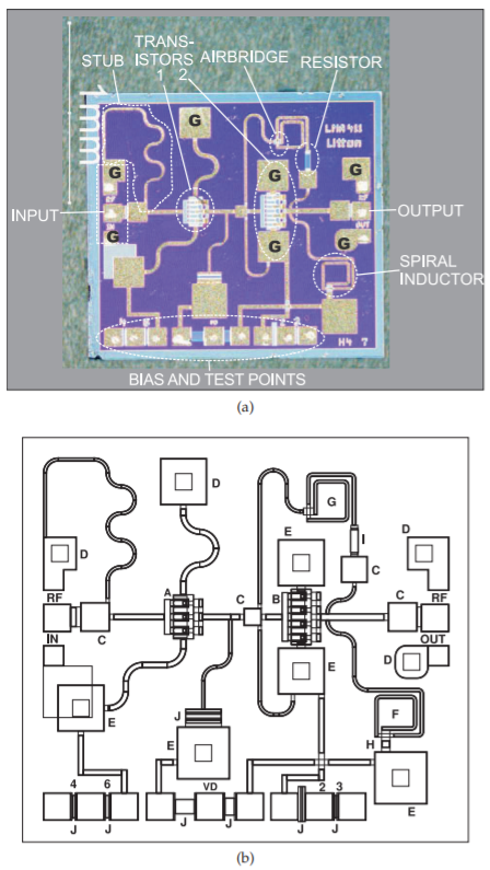
Figure \(\PageIndex{1}\): A two-stage X-band (\(8–12\text{ GHz}\)) MMIC amplifier producing \(100\text{ mW}\) of power: (a) photomicrograph with key networks identified, \(\mathbf{G}\) indicates ground; (b) annotated layout: \(\mathsf{A}\), pHEMT in first stage. \(\mathsf{B}\), pHEMT in second stage. \(\mathsf{C}\), coupling capacitors. \(\mathsf{D}\), via to backside metal. \(\mathsf{E}\), via capacitor. \(\mathsf{F}\), RF choke (bias) inductor. \(\mathsf{G}\), RF feedback inductor. \(\mathsf{H}\), airbridge. \(\mathsf{I}\), feedback resistor. \(\mathsf{J}\), bias (TaN) resistor.
probe testing and for wire-bonding. The first transistor has two source connections (at the top and bottom): a gate connection on the left and a drain connection on the right. The layout of the second transistor is the same. The larger second transistor has higher drain current. The source connections of the two transistors are grounded (indicated by the \(\mathsf{G}\) connection). The matching network is implemented using stubs and capacitors. The second
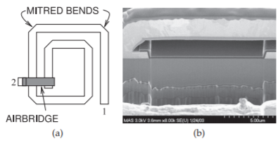
Figure \(\PageIndex{2}\): Details of the top spiral inductor in Figure \(\PageIndex{1}\)(a): (a) layout of the top spiral inductor; and (b) scanning electron microscope image of the cross section of the airbridge.
transistor has a feedback network with a spiral inductor and series resistor. Drain bias to the second transistor is through a spiral inductor. Each of the spiral inductors use an airbridge (shown in Figure \(\PageIndex{2}\)) to reduce parasitic capacitance by eliminating dielectric between the bridge metal and that of the spiral.
A second, higher-power X-band MMIC using pHEMT transistors is shown in Figure 4.10.1. This amplifier produces \(1\text{ W}\) over the \(8–12\text{ GHz}\) band. There are two stages, but the most striking contrast with the previous MMIC is the use of multiple transistors in each of the stages. The first stage has four transistors in parallel. The input matching network is integrated with a fourway power divider that drives the input of each transistor. An interstage matching network with four two-way power dividers drives the gates of \(16\) pHEMTS. A 16-way power combiner in the output matching network combines the signals at drains of each second-stage transistor, bringing them to a single output. The output combining network has four levels of two-way combiners and effectively enables transistors to be put in parallel. Putting transistors in parallel requires close matching of the transistors. Practically, the limit to the number of transistors that can be combined this way is \(16\) as there is loss with each level of combining.