
7.4: Deterministic Examples
- Page ID
- 50198

This probability model applies to any system with mutually exclusive inputs and outputs, whether or not the transitions are random. If all the transition probabilities \(c_{ji}\) are equal to either 0 or 1, then the process is deterministic.
A simple example of a deterministic process is the \(NOT\) gate, which implements Boolean negation. If the input is 1 the output is 0 and vice versa. The input and output information are the same, \(I = J\) and there is no noise or loss: \(N = L = 0\). The information that gets through the gate is \(M = I\). See Figure 7.7(a).
A slightly more complex deterministic process is the exclusive or, \(XOR\) gate. This is a Boolean function of two input variables and therefore there are four possible input values. When the gate is represented by
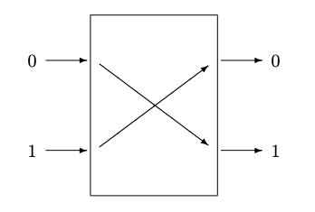
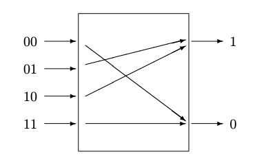
Figure 7.7: Probability models of deterministic gates
a circuit diagram, there are two input wires representing the two inputs. When the gate is represented as a discrete process using a probability diagram like Figure 7.7(b), there are four mutually exclusive inputs and two mutually exclusive outputs. If the probabilities of the four inputs are each 0.25, then \(I\) = 2 bits, and the two output probabilities are each 0.5 so \(J\) = 1 bit. There is therefore 1 bit of loss, and the mutual information is 1 bit. The loss arises from the fact that two different inputs produce the same output; for example if the output 1 is observed the input could be either 01 or 10. There is no noise introduced into the output because each of the transition parameters is either 0 or 1, i.e., there are no inputs with multiple transition paths coming from them.
Other, more complex logic functions can be represented in similar ways. However, for logic functions with n physical inputs, a probability diagram is awkward if \(n\) is larger than 3 or 4 because the number of inputs is 2\(^n\).