
7.3: Bending moments and beam curvatures
- Page ID
- 7823
")
\( \newcommand{\vecs}[1]{\overset { \scriptstyle \rightharpoonup} {\mathbf{#1}} } \)
\( \newcommand{\vecd}[1]{\overset{-\!-\!\rightharpoonup}{\vphantom{a}\smash {#1}}} \)
\( \newcommand{\dsum}{\displaystyle\sum\limits} \)
\( \newcommand{\dint}{\displaystyle\int\limits} \)
\( \newcommand{\dlim}{\displaystyle\lim\limits} \)
\( \newcommand{\id}{\mathrm{id}}\) \( \newcommand{\Span}{\mathrm{span}}\)
( \newcommand{\kernel}{\mathrm{null}\,}\) \( \newcommand{\range}{\mathrm{range}\,}\)
\( \newcommand{\RealPart}{\mathrm{Re}}\) \( \newcommand{\ImaginaryPart}{\mathrm{Im}}\)
\( \newcommand{\Argument}{\mathrm{Arg}}\) \( \newcommand{\norm}[1]{\| #1 \|}\)
\( \newcommand{\inner}[2]{\langle #1, #2 \rangle}\)
\( \newcommand{\Span}{\mathrm{span}}\)
\( \newcommand{\id}{\mathrm{id}}\)
\( \newcommand{\Span}{\mathrm{span}}\)
\( \newcommand{\kernel}{\mathrm{null}\,}\)
\( \newcommand{\range}{\mathrm{range}\,}\)
\( \newcommand{\RealPart}{\mathrm{Re}}\)
\( \newcommand{\ImaginaryPart}{\mathrm{Im}}\)
\( \newcommand{\Argument}{\mathrm{Arg}}\)
\( \newcommand{\norm}[1]{\| #1 \|}\)
\( \newcommand{\inner}[2]{\langle #1, #2 \rangle}\)
\( \newcommand{\Span}{\mathrm{span}}\) \( \newcommand{\AA}{\unicode[.8,0]{x212B}}\)
\( \newcommand{\vectorA}[1]{\vec{#1}} % arrow\)
\( \newcommand{\vectorAt}[1]{\vec{\text{#1}}} % arrow\)
\( \newcommand{\vectorB}[1]{\overset { \scriptstyle \rightharpoonup} {\mathbf{#1}} } \)
\( \newcommand{\vectorC}[1]{\textbf{#1}} \)
\( \newcommand{\vectorD}[1]{\overrightarrow{#1}} \)
\( \newcommand{\vectorDt}[1]{\overrightarrow{\text{#1}}} \)
\( \newcommand{\vectE}[1]{\overset{-\!-\!\rightharpoonup}{\vphantom{a}\smash{\mathbf {#1}}}} \)
\( \newcommand{\vecs}[1]{\overset { \scriptstyle \rightharpoonup} {\mathbf{#1}} } \)
\(\newcommand{\longvect}{\overrightarrow}\)
\( \newcommand{\vecd}[1]{\overset{-\!-\!\rightharpoonup}{\vphantom{a}\smash {#1}}} \)
\(\newcommand{\avec}{\mathbf a}\) \(\newcommand{\bvec}{\mathbf b}\) \(\newcommand{\cvec}{\mathbf c}\) \(\newcommand{\dvec}{\mathbf d}\) \(\newcommand{\dtil}{\widetilde{\mathbf d}}\) \(\newcommand{\evec}{\mathbf e}\) \(\newcommand{\fvec}{\mathbf f}\) \(\newcommand{\nvec}{\mathbf n}\) \(\newcommand{\pvec}{\mathbf p}\) \(\newcommand{\qvec}{\mathbf q}\) \(\newcommand{\svec}{\mathbf s}\) \(\newcommand{\tvec}{\mathbf t}\) \(\newcommand{\uvec}{\mathbf u}\) \(\newcommand{\vvec}{\mathbf v}\) \(\newcommand{\wvec}{\mathbf w}\) \(\newcommand{\xvec}{\mathbf x}\) \(\newcommand{\yvec}{\mathbf y}\) \(\newcommand{\zvec}{\mathbf z}\) \(\newcommand{\rvec}{\mathbf r}\) \(\newcommand{\mvec}{\mathbf m}\) \(\newcommand{\zerovec}{\mathbf 0}\) \(\newcommand{\onevec}{\mathbf 1}\) \(\newcommand{\real}{\mathbb R}\) \(\newcommand{\twovec}[2]{\left[\begin{array}{r}#1 \\ #2 \end{array}\right]}\) \(\newcommand{\ctwovec}[2]{\left[\begin{array}{c}#1 \\ #2 \end{array}\right]}\) \(\newcommand{\threevec}[3]{\left[\begin{array}{r}#1 \\ #2 \\ #3 \end{array}\right]}\) \(\newcommand{\cthreevec}[3]{\left[\begin{array}{c}#1 \\ #2 \\ #3 \end{array}\right]}\) \(\newcommand{\fourvec}[4]{\left[\begin{array}{r}#1 \\ #2 \\ #3 \\ #4 \end{array}\right]}\) \(\newcommand{\cfourvec}[4]{\left[\begin{array}{c}#1 \\ #2 \\ #3 \\ #4 \end{array}\right]}\) \(\newcommand{\fivevec}[5]{\left[\begin{array}{r}#1 \\ #2 \\ #3 \\ #4 \\ #5 \\ \end{array}\right]}\) \(\newcommand{\cfivevec}[5]{\left[\begin{array}{c}#1 \\ #2 \\ #3 \\ #4 \\ #5 \\ \end{array}\right]}\) \(\newcommand{\mattwo}[4]{\left[\begin{array}{rr}#1 \amp #2 \\ #3 \amp #4 \\ \end{array}\right]}\) \(\newcommand{\laspan}[1]{\text{Span}\{#1\}}\) \(\newcommand{\bcal}{\cal B}\) \(\newcommand{\ccal}{\cal C}\) \(\newcommand{\scal}{\cal S}\) \(\newcommand{\wcal}{\cal W}\) \(\newcommand{\ecal}{\cal E}\) \(\newcommand{\coords}[2]{\left\{#1\right\}_{#2}}\) \(\newcommand{\gray}[1]{\color{gray}{#1}}\) \(\newcommand{\lgray}[1]{\color{lightgray}{#1}}\) \(\newcommand{\rank}{\operatorname{rank}}\) \(\newcommand{\row}{\text{Row}}\) \(\newcommand{\col}{\text{Col}}\) \(\renewcommand{\row}{\text{Row}}\) \(\newcommand{\nul}{\text{Nul}}\) \(\newcommand{\var}{\text{Var}}\) \(\newcommand{\corr}{\text{corr}}\) \(\newcommand{\len}[1]{\left|#1\right|}\) \(\newcommand{\bbar}{\overline{\bvec}}\) \(\newcommand{\bhat}{\widehat{\bvec}}\) \(\newcommand{\bperp}{\bvec^\perp}\) \(\newcommand{\xhat}{\widehat{\xvec}}\) \(\newcommand{\vhat}{\widehat{\vvec}}\) \(\newcommand{\uhat}{\widehat{\uvec}}\) \(\newcommand{\what}{\widehat{\wvec}}\) \(\newcommand{\Sighat}{\widehat{\Sigma}}\) \(\newcommand{\lt}{<}\) \(\newcommand{\gt}{>}\) \(\newcommand{\amp}{&}\) \(\definecolor{fillinmathshade}{gray}{0.9}\)Bending moments are produced by transverse loads applied to beams. The simplest case is the cantilever beam , widely encountered in balconies, aircraft wings, diving boards etc. The bending moment acting on a section of the beam, due to an applied transverse force, is given by the product of the applied force and its distance from that section. It thus has units of N m. It is balanced by the internal moment arising from the stresses generated. This is given by a summation of all of the internal moments acting on individual elements within the section. These are given by the force acting on the element (stress times area of element) multiplied by its distance from the neutral axis, y .
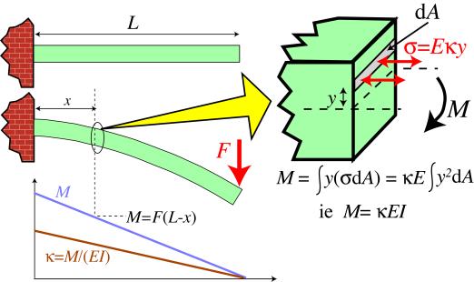
Balancing the external and internal moments during the bending of a cantilever beam
Therefore, the bending moment, M , in a loaded beam can be written in the form
\[M=\int y(\sigma d A)\]
The concept of the curvature of a beam, κ, is central to the understanding of beam bending. The figure below, which refers now to a solid beam, rather than the hollow pole shown in the previous section, shows that the axial strain, ε, is given by the ratio y / R . Equivalently, 1/R (the "curvature", κ ) is equal to the through-thickness gradient of axial strain. It follows that the axial stress at a distance y from the Neutral axis of the beam is given by
σ = E κ y
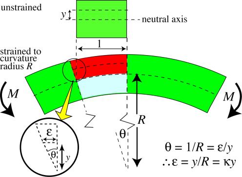
Relation between the radius of curvature, R, beam curvature, κ , and the strains within a beam subjected to a bending moment.
The bending moment can thus be expressed as
\[M=\int y(E \kappa y d A)=\kappa E \int y^{2} d A\]
This can be presented more compactly by defining I (the second moment of area , or "moment of inertia") as
\[I=\int_{0}^{y_{\max }} y^{2} d A\]
The units of I are m 4 . The value of I is dependent solely on the beam sectional shape.
Example \(\PageIndex{1}\)
Calculate I for a rectangular and a circular beam


Solution
The second moment of area for a rectangular section beam of width w and thickness h is given by
\[I=\int_{0}^{h / 2} y^{2} d A=2 \int_{0}^{h / 2} y^{2} w \mathrm{d} y=2 w\left[\frac{y^{3}}{3}\right]_{0}^{h / 2}=\frac{w h^{3}}{12}\]
The corresponding operation for a circular cross-section of diameter D gives
\[I=\int_{A} y^{2} \mathrm{d} A=\int_{\theta=0 r-0}^{2 \pi D / 2}(r \sin \theta)^{2}[(r \mathrm{d} \theta) \mathrm{d} r]=\int_{\theta=0}^{2 \pi}\left\{\int_{r=0}^{D / 2} r^{3} \mathrm{d} r\right\} \sin ^{2} \theta \mathrm{d} \theta\]
\[=\frac{D^{4}}{64} \int_{\theta=0}^{2 \pi} \sin ^{2} \theta \mathrm{d} \theta=\frac{D^{4}}{64} \int_{\theta=0}^{2 \pi}\left(\frac{1-\cos 2 \theta}{2}\right) \mathrm{d} \theta=\frac{D^{4}}{64}\left[\frac{\theta}{2}-\frac{\sin 2 \theta}{4}\right]_{0}^{2 \pi}=\frac{\pi D^{4}}{64}\]
The moment can now be written as
\[M=\kappa E I\]
These equations allow the curvature distribution along the length of a beam (ie its shape), and the stress distribution within it, to be calculated for any given set of applied forces. The following simulation implements these equations for a user-controlled beam shape and set of forces. The 3-point bending and 4-point bending loading configurations in this simulation are SYMMETRICAL, with the upward forces, denoted by arrows, outside of the downward force(s), denoted by hooks
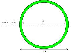
A fruitful approach to designing beams which are both light and stiff is to make them hollow. Calculation of the second moment of area for hollow beams is very straightforward, since it is obtained by simply subtracting the I of the missing section from that of the overall section. For example, that for a cylindrical tube is given by
\[I=I_{\text {complete section }}-I_{\text {missing section }}=\frac{\pi D^{4}}{64}-\frac{\pi d^{4}}{64}\]