24.6: Alternatives to Aluminium Metallization
- Page ID
- 32720
\( \newcommand{\vecs}[1]{\overset { \scriptstyle \rightharpoonup} {\mathbf{#1}} } \)
\( \newcommand{\vecd}[1]{\overset{-\!-\!\rightharpoonup}{\vphantom{a}\smash {#1}}} \)
\( \newcommand{\dsum}{\displaystyle\sum\limits} \)
\( \newcommand{\dint}{\displaystyle\int\limits} \)
\( \newcommand{\dlim}{\displaystyle\lim\limits} \)
\( \newcommand{\id}{\mathrm{id}}\) \( \newcommand{\Span}{\mathrm{span}}\)
( \newcommand{\kernel}{\mathrm{null}\,}\) \( \newcommand{\range}{\mathrm{range}\,}\)
\( \newcommand{\RealPart}{\mathrm{Re}}\) \( \newcommand{\ImaginaryPart}{\mathrm{Im}}\)
\( \newcommand{\Argument}{\mathrm{Arg}}\) \( \newcommand{\norm}[1]{\| #1 \|}\)
\( \newcommand{\inner}[2]{\langle #1, #2 \rangle}\)
\( \newcommand{\Span}{\mathrm{span}}\)
\( \newcommand{\id}{\mathrm{id}}\)
\( \newcommand{\Span}{\mathrm{span}}\)
\( \newcommand{\kernel}{\mathrm{null}\,}\)
\( \newcommand{\range}{\mathrm{range}\,}\)
\( \newcommand{\RealPart}{\mathrm{Re}}\)
\( \newcommand{\ImaginaryPart}{\mathrm{Im}}\)
\( \newcommand{\Argument}{\mathrm{Arg}}\)
\( \newcommand{\norm}[1]{\| #1 \|}\)
\( \newcommand{\inner}[2]{\langle #1, #2 \rangle}\)
\( \newcommand{\Span}{\mathrm{span}}\) \( \newcommand{\AA}{\unicode[.8,0]{x212B}}\)
\( \newcommand{\vectorA}[1]{\vec{#1}} % arrow\)
\( \newcommand{\vectorAt}[1]{\vec{\text{#1}}} % arrow\)
\( \newcommand{\vectorB}[1]{\overset { \scriptstyle \rightharpoonup} {\mathbf{#1}} } \)
\( \newcommand{\vectorC}[1]{\textbf{#1}} \)
\( \newcommand{\vectorD}[1]{\overrightarrow{#1}} \)
\( \newcommand{\vectorDt}[1]{\overrightarrow{\text{#1}}} \)
\( \newcommand{\vectE}[1]{\overset{-\!-\!\rightharpoonup}{\vphantom{a}\smash{\mathbf {#1}}}} \)
\( \newcommand{\vecs}[1]{\overset { \scriptstyle \rightharpoonup} {\mathbf{#1}} } \)
\(\newcommand{\longvect}{\overrightarrow}\)
\( \newcommand{\vecd}[1]{\overset{-\!-\!\rightharpoonup}{\vphantom{a}\smash {#1}}} \)
\(\newcommand{\avec}{\mathbf a}\) \(\newcommand{\bvec}{\mathbf b}\) \(\newcommand{\cvec}{\mathbf c}\) \(\newcommand{\dvec}{\mathbf d}\) \(\newcommand{\dtil}{\widetilde{\mathbf d}}\) \(\newcommand{\evec}{\mathbf e}\) \(\newcommand{\fvec}{\mathbf f}\) \(\newcommand{\nvec}{\mathbf n}\) \(\newcommand{\pvec}{\mathbf p}\) \(\newcommand{\qvec}{\mathbf q}\) \(\newcommand{\svec}{\mathbf s}\) \(\newcommand{\tvec}{\mathbf t}\) \(\newcommand{\uvec}{\mathbf u}\) \(\newcommand{\vvec}{\mathbf v}\) \(\newcommand{\wvec}{\mathbf w}\) \(\newcommand{\xvec}{\mathbf x}\) \(\newcommand{\yvec}{\mathbf y}\) \(\newcommand{\zvec}{\mathbf z}\) \(\newcommand{\rvec}{\mathbf r}\) \(\newcommand{\mvec}{\mathbf m}\) \(\newcommand{\zerovec}{\mathbf 0}\) \(\newcommand{\onevec}{\mathbf 1}\) \(\newcommand{\real}{\mathbb R}\) \(\newcommand{\twovec}[2]{\left[\begin{array}{r}#1 \\ #2 \end{array}\right]}\) \(\newcommand{\ctwovec}[2]{\left[\begin{array}{c}#1 \\ #2 \end{array}\right]}\) \(\newcommand{\threevec}[3]{\left[\begin{array}{r}#1 \\ #2 \\ #3 \end{array}\right]}\) \(\newcommand{\cthreevec}[3]{\left[\begin{array}{c}#1 \\ #2 \\ #3 \end{array}\right]}\) \(\newcommand{\fourvec}[4]{\left[\begin{array}{r}#1 \\ #2 \\ #3 \\ #4 \end{array}\right]}\) \(\newcommand{\cfourvec}[4]{\left[\begin{array}{c}#1 \\ #2 \\ #3 \\ #4 \end{array}\right]}\) \(\newcommand{\fivevec}[5]{\left[\begin{array}{r}#1 \\ #2 \\ #3 \\ #4 \\ #5 \\ \end{array}\right]}\) \(\newcommand{\cfivevec}[5]{\left[\begin{array}{c}#1 \\ #2 \\ #3 \\ #4 \\ #5 \\ \end{array}\right]}\) \(\newcommand{\mattwo}[4]{\left[\begin{array}{rr}#1 \amp #2 \\ #3 \amp #4 \\ \end{array}\right]}\) \(\newcommand{\laspan}[1]{\text{Span}\{#1\}}\) \(\newcommand{\bcal}{\cal B}\) \(\newcommand{\ccal}{\cal C}\) \(\newcommand{\scal}{\cal S}\) \(\newcommand{\wcal}{\cal W}\) \(\newcommand{\ecal}{\cal E}\) \(\newcommand{\coords}[2]{\left\{#1\right\}_{#2}}\) \(\newcommand{\gray}[1]{\color{gray}{#1}}\) \(\newcommand{\lgray}[1]{\color{lightgray}{#1}}\) \(\newcommand{\rank}{\operatorname{rank}}\) \(\newcommand{\row}{\text{Row}}\) \(\newcommand{\col}{\text{Col}}\) \(\renewcommand{\row}{\text{Row}}\) \(\newcommand{\nul}{\text{Nul}}\) \(\newcommand{\var}{\text{Var}}\) \(\newcommand{\corr}{\text{corr}}\) \(\newcommand{\len}[1]{\left|#1\right|}\) \(\newcommand{\bbar}{\overline{\bvec}}\) \(\newcommand{\bhat}{\widehat{\bvec}}\) \(\newcommand{\bperp}{\bvec^\perp}\) \(\newcommand{\xhat}{\widehat{\xvec}}\) \(\newcommand{\vhat}{\widehat{\vvec}}\) \(\newcommand{\uhat}{\widehat{\uvec}}\) \(\newcommand{\what}{\widehat{\wvec}}\) \(\newcommand{\Sighat}{\widehat{\Sigma}}\) \(\newcommand{\lt}{<}\) \(\newcommand{\gt}{>}\) \(\newcommand{\amp}{&}\) \(\definecolor{fillinmathshade}{gray}{0.9}\)Technological pressures on the speed and reliability of integrated circuits has caused a need for changes to be made in the choices of materials used for metallization lines today. In selecting a material for metallization, it is necessary to consider what its desirable properties would be. These include:
- low resistivity
- mechanical stability, good adherence, and low stress
- easy to form
- easy to etch for pattern generation
- stable throughout processing, including: high temperature sinter, dry or wet oxidation, gettering, phosphorus glass (or any other materials) passivation, and metallization
- should not contaminate devices, wafers or working apparatus
- should be stable in oxidation ambients and is able to form a stable oxide
- no reaction with other components
- good surface smoothness
- low contact resistance, minimal junction penetration and low electromigration for use in window contacts
- very low cost
During the growth of the microelectronics industry, metallization lines have moved from the use of pure Al to Al-Cu alloy and currently to pure Cu.
Using Pure Aluminium
Commercially, it would be assumed that a material having the lowest resistivity would be used for IC interconnections. This is because, the lower the resistivity of the material, the smaller the resultant RC-delay, and the faster the signal transmission between devices – in order to be useful, resistivities must be below 50 μΩ cm.
|
Metal |
Electrical resistivity (at 20 ºC) / µΩ cm |
|---|---|
|
Al |
2.65 |
Data obtained from Metals Handbook, 8th Edition, ASM, Metals Park, Ohio.
Yet, the standard interconnection material previously used was Al, despite having other materials such as Ag, Cu and Au with lower resistivity values (as shown in the table). This is because it was found that:
- Ag is too prone to attack by S and O, and could not maintain its low resistivity over the device lifetime.
- Cu is prone to oxidation resulting in a vast increase in resistivity of the material.
- Ag and Au are very difficult to deposit as very low resistance films.
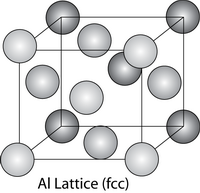
Al has low resistivity and can be easily deposited. It can be dry etched, does not contaminate Si as it forms a protective Al2O3 oxide layer which prevents further oxidation, has excellent adhesion to dielectrics, and is able to form ohmic contacts.

These factors resulted in the universal use of Al-based metallization in ICs. Unfortunately, Al has a problem forming contacts with shallow junctions, has difficulty achieving a good mechanical and electrical connection as a vacuum deposited thin film and is very prone to electromigration failure.
Using Aluminium-Copper Alloys
Due to problems associated with electromigration in pure Al metallization, there was a real need to improve the metallization. In the mid 1960s, a mis-focused electron beam evaporated some Cu, instead of the charge metal (Al). The resultant Al-Cu alloy films were found to be significantly resistant to electromigration.

This is shown in the table below, as the amount of Cu content increases the critical product (jl)c is increased and the effective charge, Z*, is decreased.
|
Cu content (wt%) |
Critical product (jl)c/ A cm-1 |
Effective charge number, Z* |
|
|---|---|---|---|
|
Al standard |
0 |
244 |
18 |
Data from: ‘Quantitative analysis of electromigration damage in Al-based conductor lines’ by O. Kraft et.al. J. Mater. Res., 12 (1997) 2027.
Reducing the effect of electromigration
A commonly used Al-Cu alloy is Al-1.5at%Si-4at%Cu. Despite its increase in resistivity from 2.86 μΩ cm (pure Al) to 3 μΩ (Al-Cu alloy), the improvement of electromigration resistance made Al-Cu alloys the system of choice in metallization.
There are several reasons for the increase in electromigration resistance:
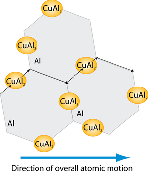
- As most mass transport in Al occurs along grain boundaries, the addition of Si and Cu reduced the grain boundary diffusion rate, by increasing the activation energy of grain-boundary diffusion.
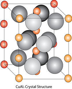
- The addition of Cu to the Al alloy, results in the formation of CuAl2 precipitates. These precipitates form primarily on grain boundaries, impeding grain boundary diffusion. The precipitates also act as reservoirs of Cu, delaying any damage, as the precipitate must dissolve before the level of Cu in grain boundaries can fall significantly. Dissolution is rather slow as a steady-state flow of Cu can be established from precipitate to precipitate before migration takes place.

Using Pure Copper
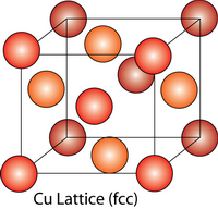
The trend towards narrower interconnections, and faster and more reliable devices resulted in the examination of the possibility of using Cu-based metallization. It was found that the change to a Cu-based material greatly improved the reliability of devices.

A comparison (see table below) shows the reasons for the currently increasing use of Cu-based metallization in the microelectronics industry:
|
Advantages of Cu |
Disadvantages of Cu |
|---|---|
|
|
Due to the favourable properties of Cu, it is possible for the chip size to be reduced, whilst increasing the speed and complexity of the device.
Cu has proved to be an excellent metallization material as it has an improved current carrying capability and high electromigration resistance. The disadvantages have been overcome using new thin-film technology and careful materials selection. It is therefore possible for component size to be further reduced, increasing the speed and complexity of the device.
This is sufficient for now, though there is a continuing need to achieve high conductivity and minuscule dielectric constants for future devices. Therefore, in order for the microelectronics industry to keep up with Moore’s Law and the ever increasing consumer needs, there needs to be introduction of new materials and processes.


