27.4: Metals
- Page ID
- 32807
\( \newcommand{\vecs}[1]{\overset { \scriptstyle \rightharpoonup} {\mathbf{#1}} } \)
\( \newcommand{\vecd}[1]{\overset{-\!-\!\rightharpoonup}{\vphantom{a}\smash {#1}}} \)
\( \newcommand{\dsum}{\displaystyle\sum\limits} \)
\( \newcommand{\dint}{\displaystyle\int\limits} \)
\( \newcommand{\dlim}{\displaystyle\lim\limits} \)
\( \newcommand{\id}{\mathrm{id}}\) \( \newcommand{\Span}{\mathrm{span}}\)
( \newcommand{\kernel}{\mathrm{null}\,}\) \( \newcommand{\range}{\mathrm{range}\,}\)
\( \newcommand{\RealPart}{\mathrm{Re}}\) \( \newcommand{\ImaginaryPart}{\mathrm{Im}}\)
\( \newcommand{\Argument}{\mathrm{Arg}}\) \( \newcommand{\norm}[1]{\| #1 \|}\)
\( \newcommand{\inner}[2]{\langle #1, #2 \rangle}\)
\( \newcommand{\Span}{\mathrm{span}}\)
\( \newcommand{\id}{\mathrm{id}}\)
\( \newcommand{\Span}{\mathrm{span}}\)
\( \newcommand{\kernel}{\mathrm{null}\,}\)
\( \newcommand{\range}{\mathrm{range}\,}\)
\( \newcommand{\RealPart}{\mathrm{Re}}\)
\( \newcommand{\ImaginaryPart}{\mathrm{Im}}\)
\( \newcommand{\Argument}{\mathrm{Arg}}\)
\( \newcommand{\norm}[1]{\| #1 \|}\)
\( \newcommand{\inner}[2]{\langle #1, #2 \rangle}\)
\( \newcommand{\Span}{\mathrm{span}}\) \( \newcommand{\AA}{\unicode[.8,0]{x212B}}\)
\( \newcommand{\vectorA}[1]{\vec{#1}} % arrow\)
\( \newcommand{\vectorAt}[1]{\vec{\text{#1}}} % arrow\)
\( \newcommand{\vectorB}[1]{\overset { \scriptstyle \rightharpoonup} {\mathbf{#1}} } \)
\( \newcommand{\vectorC}[1]{\textbf{#1}} \)
\( \newcommand{\vectorD}[1]{\overrightarrow{#1}} \)
\( \newcommand{\vectorDt}[1]{\overrightarrow{\text{#1}}} \)
\( \newcommand{\vectE}[1]{\overset{-\!-\!\rightharpoonup}{\vphantom{a}\smash{\mathbf {#1}}}} \)
\( \newcommand{\vecs}[1]{\overset { \scriptstyle \rightharpoonup} {\mathbf{#1}} } \)
\(\newcommand{\longvect}{\overrightarrow}\)
\( \newcommand{\vecd}[1]{\overset{-\!-\!\rightharpoonup}{\vphantom{a}\smash {#1}}} \)
\(\newcommand{\avec}{\mathbf a}\) \(\newcommand{\bvec}{\mathbf b}\) \(\newcommand{\cvec}{\mathbf c}\) \(\newcommand{\dvec}{\mathbf d}\) \(\newcommand{\dtil}{\widetilde{\mathbf d}}\) \(\newcommand{\evec}{\mathbf e}\) \(\newcommand{\fvec}{\mathbf f}\) \(\newcommand{\nvec}{\mathbf n}\) \(\newcommand{\pvec}{\mathbf p}\) \(\newcommand{\qvec}{\mathbf q}\) \(\newcommand{\svec}{\mathbf s}\) \(\newcommand{\tvec}{\mathbf t}\) \(\newcommand{\uvec}{\mathbf u}\) \(\newcommand{\vvec}{\mathbf v}\) \(\newcommand{\wvec}{\mathbf w}\) \(\newcommand{\xvec}{\mathbf x}\) \(\newcommand{\yvec}{\mathbf y}\) \(\newcommand{\zvec}{\mathbf z}\) \(\newcommand{\rvec}{\mathbf r}\) \(\newcommand{\mvec}{\mathbf m}\) \(\newcommand{\zerovec}{\mathbf 0}\) \(\newcommand{\onevec}{\mathbf 1}\) \(\newcommand{\real}{\mathbb R}\) \(\newcommand{\twovec}[2]{\left[\begin{array}{r}#1 \\ #2 \end{array}\right]}\) \(\newcommand{\ctwovec}[2]{\left[\begin{array}{c}#1 \\ #2 \end{array}\right]}\) \(\newcommand{\threevec}[3]{\left[\begin{array}{r}#1 \\ #2 \\ #3 \end{array}\right]}\) \(\newcommand{\cthreevec}[3]{\left[\begin{array}{c}#1 \\ #2 \\ #3 \end{array}\right]}\) \(\newcommand{\fourvec}[4]{\left[\begin{array}{r}#1 \\ #2 \\ #3 \\ #4 \end{array}\right]}\) \(\newcommand{\cfourvec}[4]{\left[\begin{array}{c}#1 \\ #2 \\ #3 \\ #4 \end{array}\right]}\) \(\newcommand{\fivevec}[5]{\left[\begin{array}{r}#1 \\ #2 \\ #3 \\ #4 \\ #5 \\ \end{array}\right]}\) \(\newcommand{\cfivevec}[5]{\left[\begin{array}{c}#1 \\ #2 \\ #3 \\ #4 \\ #5 \\ \end{array}\right]}\) \(\newcommand{\mattwo}[4]{\left[\begin{array}{rr}#1 \amp #2 \\ #3 \amp #4 \\ \end{array}\right]}\) \(\newcommand{\laspan}[1]{\text{Span}\{#1\}}\) \(\newcommand{\bcal}{\cal B}\) \(\newcommand{\ccal}{\cal C}\) \(\newcommand{\scal}{\cal S}\) \(\newcommand{\wcal}{\cal W}\) \(\newcommand{\ecal}{\cal E}\) \(\newcommand{\coords}[2]{\left\{#1\right\}_{#2}}\) \(\newcommand{\gray}[1]{\color{gray}{#1}}\) \(\newcommand{\lgray}[1]{\color{lightgray}{#1}}\) \(\newcommand{\rank}{\operatorname{rank}}\) \(\newcommand{\row}{\text{Row}}\) \(\newcommand{\col}{\text{Col}}\) \(\renewcommand{\row}{\text{Row}}\) \(\newcommand{\nul}{\text{Nul}}\) \(\newcommand{\var}{\text{Var}}\) \(\newcommand{\corr}{\text{corr}}\) \(\newcommand{\len}[1]{\left|#1\right|}\) \(\newcommand{\bbar}{\overline{\bvec}}\) \(\newcommand{\bhat}{\widehat{\bvec}}\) \(\newcommand{\bperp}{\bvec^\perp}\) \(\newcommand{\xhat}{\widehat{\xvec}}\) \(\newcommand{\vhat}{\widehat{\vvec}}\) \(\newcommand{\uhat}{\widehat{\uvec}}\) \(\newcommand{\what}{\widehat{\wvec}}\) \(\newcommand{\Sighat}{\widehat{\Sigma}}\) \(\newcommand{\lt}{<}\) \(\newcommand{\gt}{>}\) \(\newcommand{\amp}{&}\) \(\definecolor{fillinmathshade}{gray}{0.9}\)Metals are extremely widely used in manufacturing, often for mechanical or electrical properties. They are often easily shaped and have good mechanical properties so they may be used in ‘structural’ elements of an article, and they also have good conduction (electrical and thermal) and so may also be used, for example, in electrical wiring. Familiar metals can often be reasonably well identified by eye (see examples below), but there are more complex methods of metal identification available too.

Techniques for the Identification of Metals
One very easy test for a metal is to see if the component is magnetic, this narrows down the possible materials to those that are ferromagnetic (most commonly iron or nickel).
Simple corrosion tests involving immersing a scratched sample (to remove any coating) in water (or some other electrolyte) can be helpful. Leaving a sample in water overnight might reveal rusting. For example a scratched zinc coated steel sample would not rust due to the zinc offering sacrificial protection. However, a scratched tin coated steel sample would rust, because the tin is supposed to act as a barrier between the steel and air. This is especially useful for ferrous alloys as corrosion resistance is very often a concern for these (and they are very common).
Optical Microscopy
This involves looking at mounted, polished and etched samples under a light microscope. It reveals the microstructure of the sample; this can give information on both the composition and processing of the component.
See Optical Microscopy and Specimen Preparation TLP for more information on how to go about this.
 |
 |
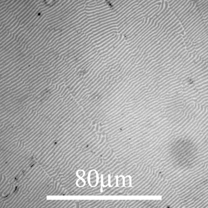
| Al-Cu Eutectic composition This is an Al-Cu alloy showing a very clear eutectic lamellar microstructure. (See micrograph library entry for more information) |
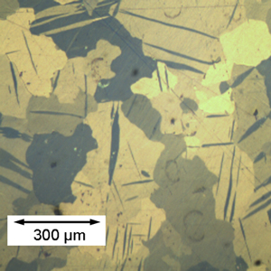
Cold rolled zinc showing deformation twins This is zinc, it has been cold rolled as can be seen from lenticular deformation twins |
See the DoITPoMS Micrograph Library for further examples.
The benefits of this method are that optical micrographs can reveal a large amount of information about a metallographic sample, and it is possible to find known examples (see above links) to compare your work to. After an initial examination by eye and consideration of properties, optical microscopy is an important step in the characterisation of metals. It can reveal many things that the initial examination does not.
Scanning Electron Microscopy (SEM)
Scanning Electron Microscopy uses a focussed beam of high-energy electrons to form images of samples. Electron Microscopy is not limited by the wavelength of light, so very closely spaced features can be resolved, so this method gives very clear high magnification images when set up correctly. It also gives a large depth of field , so rough surfaces can still be in focus.
The SEM can give very good high magnification images, again revealing more than optical microscopy could. One limitation is that the sample must be electrically conducting; the mounting polymer and the sample must both conduct electricity.
Energy Dispersive X-ray Spectroscopy (EDS)
This is a technique often used in conjunction with the SEM, with an electron beam of ~20 keV. The beam strikes the sample resulting in X-rays being emitted; the X-rays are collected and the intensities and energies examined. The results can determine the atomic composition of the sample at the point of beam-sample interaction.
Examples: It can reveal the composition of a very thin coating; for example by taking a linescan. The diagram below shows results for a linescan taken across a coating, showing a layer of copper and a finer layer of nickel on an iron alloy (all other elements were ignored). This may not be easy to tell from optical microscopy alone.

EDS can be a very helpful method of characterisation, but it is not always absolutely reliable. Elements of low atomic number (less than about 11, i.e. below sodium) are difficult to detect by EDS. There is often contamination of elements like carbon from the environment. It is important to use common sense when interpreting the EDS results; most of the time is it unlikely that very heavy elements like uranium are actually present. Results may be very good qualitatively, but care must be taken when trying to obtain and interpret quantitative results. The quantitative analysis results depend upon things like the set-up of the SEM and the geometry of the sample.
Examples of Fabrication Processes
The ease with which metals are shaped leads to a wide range of processing techniques for different end products; any coatings will also be applied by one from a range of processes. It may be possible to deduce the method of processing from the shape and the properties of the metal. The microstructure may also give further clues:
| Process | Description | Features |
| Deformation | Includes a variety of techniques including forging, extruding and drawing, see the TLP Introduction to Deformation Processes for more information | May expect to see directionality or squashed grains in places that have been stressed (see the animation) |
| Machining | Includes, for example, laser cutting and water-jet cutting as well as more conventional methods like sawing or grinding. | These methods would not result in larger scale microstructural directionality, but may show localised deformation. Can give a very good finish |
| Casting | The molten metal is set in a cast of some kind, see the Casting TLP for further details on the different kinds of casting. | There is a lot of variety of microstructure from cast products, which ranges from single crystal components to those with clear chill, columnar and equiaxed zones. |
| Carburisation – a surface heat treatment | A surface treatment in which carbon is diffused into the surface of a steel object above the ferrite-austenite transition temperature (~ 740 °C). This is done by heating the steel in a C-rich atmosphere, (e.g. in CO gas). The result is a hard, high carbon surface several hundreds of microns thick, surrounding a tough, low carbon interior. To improve the hardness, the surface may be quenched, which helps the production of martensite . | See micrograph below |

Micrograph #271
An example of carburisation; see the description in the micrograph library for further information.


