
1.3: Fundamental Concepts and Principles of Structural Analysis
- Page ID
- 42942

\( \newcommand{\vecs}[1]{\overset { \scriptstyle \rightharpoonup} {\mathbf{#1}} } \)
\( \newcommand{\vecd}[1]{\overset{-\!-\!\rightharpoonup}{\vphantom{a}\smash {#1}}} \)
\( \newcommand{\dsum}{\displaystyle\sum\limits} \)
\( \newcommand{\dint}{\displaystyle\int\limits} \)
\( \newcommand{\dlim}{\displaystyle\lim\limits} \)
\( \newcommand{\id}{\mathrm{id}}\) \( \newcommand{\Span}{\mathrm{span}}\)
( \newcommand{\kernel}{\mathrm{null}\,}\) \( \newcommand{\range}{\mathrm{range}\,}\)
\( \newcommand{\RealPart}{\mathrm{Re}}\) \( \newcommand{\ImaginaryPart}{\mathrm{Im}}\)
\( \newcommand{\Argument}{\mathrm{Arg}}\) \( \newcommand{\norm}[1]{\| #1 \|}\)
\( \newcommand{\inner}[2]{\langle #1, #2 \rangle}\)
\( \newcommand{\Span}{\mathrm{span}}\)
\( \newcommand{\id}{\mathrm{id}}\)
\( \newcommand{\Span}{\mathrm{span}}\)
\( \newcommand{\kernel}{\mathrm{null}\,}\)
\( \newcommand{\range}{\mathrm{range}\,}\)
\( \newcommand{\RealPart}{\mathrm{Re}}\)
\( \newcommand{\ImaginaryPart}{\mathrm{Im}}\)
\( \newcommand{\Argument}{\mathrm{Arg}}\)
\( \newcommand{\norm}[1]{\| #1 \|}\)
\( \newcommand{\inner}[2]{\langle #1, #2 \rangle}\)
\( \newcommand{\Span}{\mathrm{span}}\) \( \newcommand{\AA}{\unicode[.8,0]{x212B}}\)
\( \newcommand{\vectorA}[1]{\vec{#1}} % arrow\)
\( \newcommand{\vectorAt}[1]{\vec{\text{#1}}} % arrow\)
\( \newcommand{\vectorB}[1]{\overset { \scriptstyle \rightharpoonup} {\mathbf{#1}} } \)
\( \newcommand{\vectorC}[1]{\textbf{#1}} \)
\( \newcommand{\vectorD}[1]{\overrightarrow{#1}} \)
\( \newcommand{\vectorDt}[1]{\overrightarrow{\text{#1}}} \)
\( \newcommand{\vectE}[1]{\overset{-\!-\!\rightharpoonup}{\vphantom{a}\smash{\mathbf {#1}}}} \)
\( \newcommand{\vecs}[1]{\overset { \scriptstyle \rightharpoonup} {\mathbf{#1}} } \)
\(\newcommand{\longvect}{\overrightarrow}\)
\( \newcommand{\vecd}[1]{\overset{-\!-\!\rightharpoonup}{\vphantom{a}\smash {#1}}} \)
\(\newcommand{\avec}{\mathbf a}\) \(\newcommand{\bvec}{\mathbf b}\) \(\newcommand{\cvec}{\mathbf c}\) \(\newcommand{\dvec}{\mathbf d}\) \(\newcommand{\dtil}{\widetilde{\mathbf d}}\) \(\newcommand{\evec}{\mathbf e}\) \(\newcommand{\fvec}{\mathbf f}\) \(\newcommand{\nvec}{\mathbf n}\) \(\newcommand{\pvec}{\mathbf p}\) \(\newcommand{\qvec}{\mathbf q}\) \(\newcommand{\svec}{\mathbf s}\) \(\newcommand{\tvec}{\mathbf t}\) \(\newcommand{\uvec}{\mathbf u}\) \(\newcommand{\vvec}{\mathbf v}\) \(\newcommand{\wvec}{\mathbf w}\) \(\newcommand{\xvec}{\mathbf x}\) \(\newcommand{\yvec}{\mathbf y}\) \(\newcommand{\zvec}{\mathbf z}\) \(\newcommand{\rvec}{\mathbf r}\) \(\newcommand{\mvec}{\mathbf m}\) \(\newcommand{\zerovec}{\mathbf 0}\) \(\newcommand{\onevec}{\mathbf 1}\) \(\newcommand{\real}{\mathbb R}\) \(\newcommand{\twovec}[2]{\left[\begin{array}{r}#1 \\ #2 \end{array}\right]}\) \(\newcommand{\ctwovec}[2]{\left[\begin{array}{c}#1 \\ #2 \end{array}\right]}\) \(\newcommand{\threevec}[3]{\left[\begin{array}{r}#1 \\ #2 \\ #3 \end{array}\right]}\) \(\newcommand{\cthreevec}[3]{\left[\begin{array}{c}#1 \\ #2 \\ #3 \end{array}\right]}\) \(\newcommand{\fourvec}[4]{\left[\begin{array}{r}#1 \\ #2 \\ #3 \\ #4 \end{array}\right]}\) \(\newcommand{\cfourvec}[4]{\left[\begin{array}{c}#1 \\ #2 \\ #3 \\ #4 \end{array}\right]}\) \(\newcommand{\fivevec}[5]{\left[\begin{array}{r}#1 \\ #2 \\ #3 \\ #4 \\ #5 \\ \end{array}\right]}\) \(\newcommand{\cfivevec}[5]{\left[\begin{array}{c}#1 \\ #2 \\ #3 \\ #4 \\ #5 \\ \end{array}\right]}\) \(\newcommand{\mattwo}[4]{\left[\begin{array}{rr}#1 \amp #2 \\ #3 \amp #4 \\ \end{array}\right]}\) \(\newcommand{\laspan}[1]{\text{Span}\{#1\}}\) \(\newcommand{\bcal}{\cal B}\) \(\newcommand{\ccal}{\cal C}\) \(\newcommand{\scal}{\cal S}\) \(\newcommand{\wcal}{\cal W}\) \(\newcommand{\ecal}{\cal E}\) \(\newcommand{\coords}[2]{\left\{#1\right\}_{#2}}\) \(\newcommand{\gray}[1]{\color{gray}{#1}}\) \(\newcommand{\lgray}[1]{\color{lightgray}{#1}}\) \(\newcommand{\rank}{\operatorname{rank}}\) \(\newcommand{\row}{\text{Row}}\) \(\newcommand{\col}{\text{Col}}\) \(\renewcommand{\row}{\text{Row}}\) \(\newcommand{\nul}{\text{Nul}}\) \(\newcommand{\var}{\text{Var}}\) \(\newcommand{\corr}{\text{corr}}\) \(\newcommand{\len}[1]{\left|#1\right|}\) \(\newcommand{\bbar}{\overline{\bvec}}\) \(\newcommand{\bhat}{\widehat{\bvec}}\) \(\newcommand{\bperp}{\bvec^\perp}\) \(\newcommand{\xhat}{\widehat{\xvec}}\) \(\newcommand{\vhat}{\widehat{\vvec}}\) \(\newcommand{\uhat}{\widehat{\uvec}}\) \(\newcommand{\what}{\widehat{\wvec}}\) \(\newcommand{\Sighat}{\widehat{\Sigma}}\) \(\newcommand{\lt}{<}\) \(\newcommand{\gt}{>}\) \(\newcommand{\amp}{&}\) \(\definecolor{fillinmathshade}{gray}{0.9}\)Equilibrium Conditions
Civil engineering structures are designed to be at rest when acted upon by external forces. A structure at rest must satisfy the equilibrium conditions, which require that the resultant force and the resultant moment acting on a structure be equal to zero. The equilibrium conditions of a structure can be expressed mathematically as follows: \[\sum F=0, \text { and } \sum M=0\]
Compatibility of Displacement
The compatibility of displacement concept implies that when a structure deforms, members of the structure that are connected at a point remain connected at that point without void or hole. In other words, two parts of a structure are said to be compatible in displacements if the parts remain fitted together when the structure deforms due to the applied load. Compatibility of displacement is a powerful concept used in the analysis of indeterminate structures with unknown redundant forces in excess of the three equations of equilibrium. For an illustration of the concept, consider the propped cantilever beam shown in Figure 1.5a. There are four unknown reactions in the beam: the reactive moment, a vertical and horizontal reaction at the fixed end, and another vertical reaction at the prop at point B. To determine the unknown reactions in the beam, one more equation must be added to the three equations of equilibrium. The additional equation can be obtained as follows, considering the compatibility of the structure: \[\Delta_{B P}+\Delta_{B R}=0\]
In this equation, \(\Delta_{B P}\) is the displacement at point \(B\) of the structure due to the applied load \(P\) (Figure 1.5b), and \(\Delta_{B R}\) is the displacement at point \(B\) due to the reaction at the prop \(R\) (Figure 1.5c). Students should always remember that the first subscript of the displacement indicates the location where the displacement occurs, while the second subscript indicates the load causing the displacement.
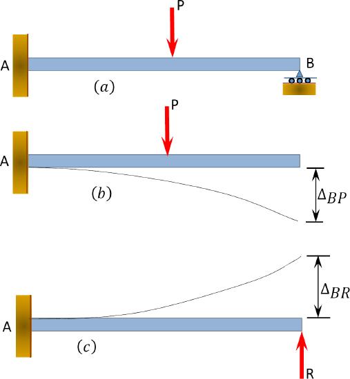
\(Fig. 1.5\). Propped cantilever beam.
Principle of Superposition
The principle of superposition is another very important principle used in structural analysis. The principle states that the load effects caused by two or more loadings in a linearly elastic structure are equal to the sum of the load effects caused by the individual loading. For an illustration, consider the cantilever beam carrying two concentrated loads \(P_{1}\), and \(P_{2}\), in Figure 1.6a. Figures 1.6b and 1.6c are the responses of the structure in terms of the displacement at the free end of the beam when acted upon by the individual loads. By the principle of superposition, the displacement at the free end of the beam is the algebraic sum of the displacements caused by the individual loads. This can is written as follows: \[\Delta_{B}=\Delta_{B P_{1}}+\Delta_{B P_{2}}\]
In this equation, \(\Delta_{B}\) is the displacement at \(B\); \(\Delta_{B P_{1}}\) and \(\Delta_{B P_{2}}\) are the displacements at \(B\) caused by the loads \(P_{1}\) and \(P_{2}\), respectively.
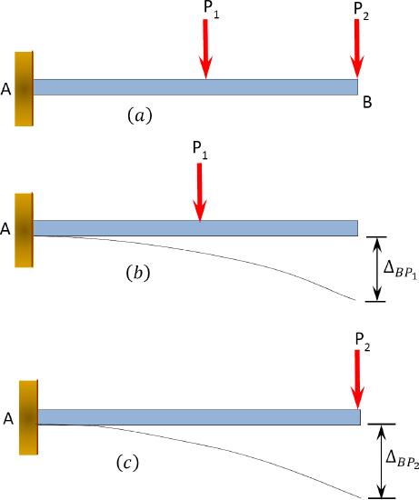
\(Fig. 1.6\). Application of the principle of superposition.
Work-Energy Principle
The work-energy principle is a very powerful tool in structural analysis. Work is defined as the product of the force and the distance traveled by the force, while energy is defined as the ability to do work. Work can be transformed into various energy, including kinetic energy, potential energy, and strain energy. In the case of a structural system, based on the law of conservation of energy, work done \(W\) is equal to the strain energy \(U\) stored when deforming the system. This is expressed mathematically as follows: \[W=U\]
Consider a case where a force \(F\) is gradually applied to a deformable structural system. By plotting the applied force against the deformation \(\Delta\) of the structure, the load-deformation plot shown in Figure 1.7a is created. In the case of linearly elastic structure, the load-deformation diagram will be as shown in Figure 1.7b. The incremental work done \(d W\) by the force when deforming the structure over an incremental displacement \(d \Delta\) is expressed as follows: \[d W=F d \Delta\]
The total work done is represented as follows: \[W=\int_{0}^{\Delta} d W=\int_{0}^{\Delta} F d \Delta\]
Thus, the strain energy is written as follows: \[U=\int_{0}^{\Delta} F d \Delta\]
The strain energy in the case of linearly elastic deformation can be obtained by computing the area under the load-deformation diagram in Figure 1.7b. This is expressed as follows: \[U=\frac{1}{2} F \Delta\]
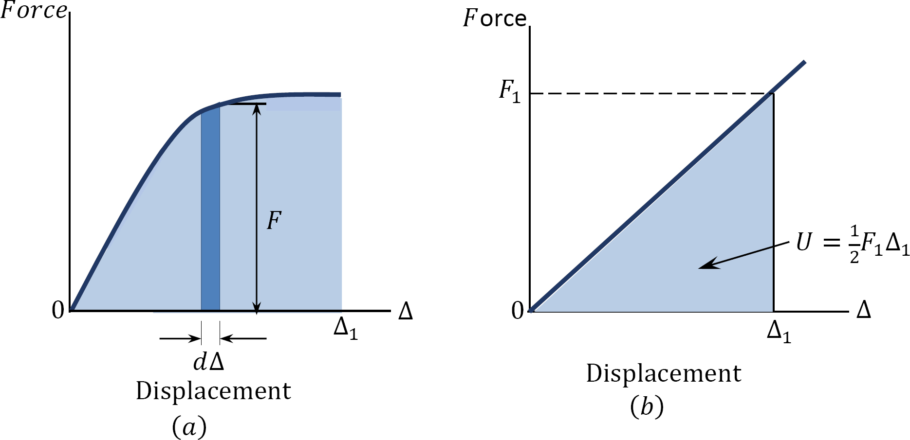
\(Fig. 1.7\). Load-deformation diagram.
Virtual Work Principle
The virtual work principle is another powerful and useful analytical tool in structural analysis. It was developed in 1717 by Johann Bernoulli. Virtual work is defined as the work done by a virtual or imaginary force acting on a deformable body through a real distance, or the work done by a real force acting on a rigid body through a virtual or fictitious displacement. To formulate this principle in the case of virtual displacements through a rigid body, consider a propped cantilever beam subjected to a concentrated load \(P\) at a distance \(x\) from the fixed end, as shown in Figure 1.8a. Suppose the beam undergoes an elementary virtual displacement \(\delta u\) at the propped end, as shown in Figure 1.8b. The total virtual work performed is expressed as follows: \[\delta W=R_{B} \delta_{u}-P \frac{X}{L} \delta u\]
Since the beam is in equilibrium, \(\delta W=0\) (by the definition of the principle of virtual work of a body).
The principle of virtual work of a rigid body states that if a rigid body is in equilibrium, the total virtual work performed by all the external forces acting on the body is zero for any virtual displacement.
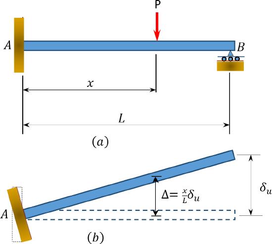
\(Fig. 1.8\). Propped cantilever beam.
Structural Idealization
Structural idealization is a process in which an actual structure and the loads acting on it are replaced by simpler models for the purpose of analysis. Civil engineering structures and their loads are most often complex and thus require rigorous analysis. To make analysis less cumbersome, structures are represented in simplified forms. The choice of an appropriate simplified model is a very important aspect of the analysis process, since the predictive response of such idealization must be the same as that of the actual structure. Figure 1.9a shows a simply supported wide-flange beam structure and its load. The plan of the same beam is shown in Figure 1.9b, and the idealization of the beam is shown in Figure 1.9c. In the idealized form, the beam is represented as a line along the beam’s neutral axis, and the load acting on the beam is shown as a point or concentrated load because the load occupies an area that is significantly less than the total area of the structure’s surface in the plane of its application. Figures 1.10a and 1.10b depict a frame and its idealization, respectively. In the idealized form, the two columns and the beam of the frame are represented by lines passing through their respective neutral axes. Figures 1.11a and 1.11b show a truss and its idealization. Members of the truss are represented by lines passing through their respective neutral axes, and the connection of members at the joints are assumed to be by frictionless pins.
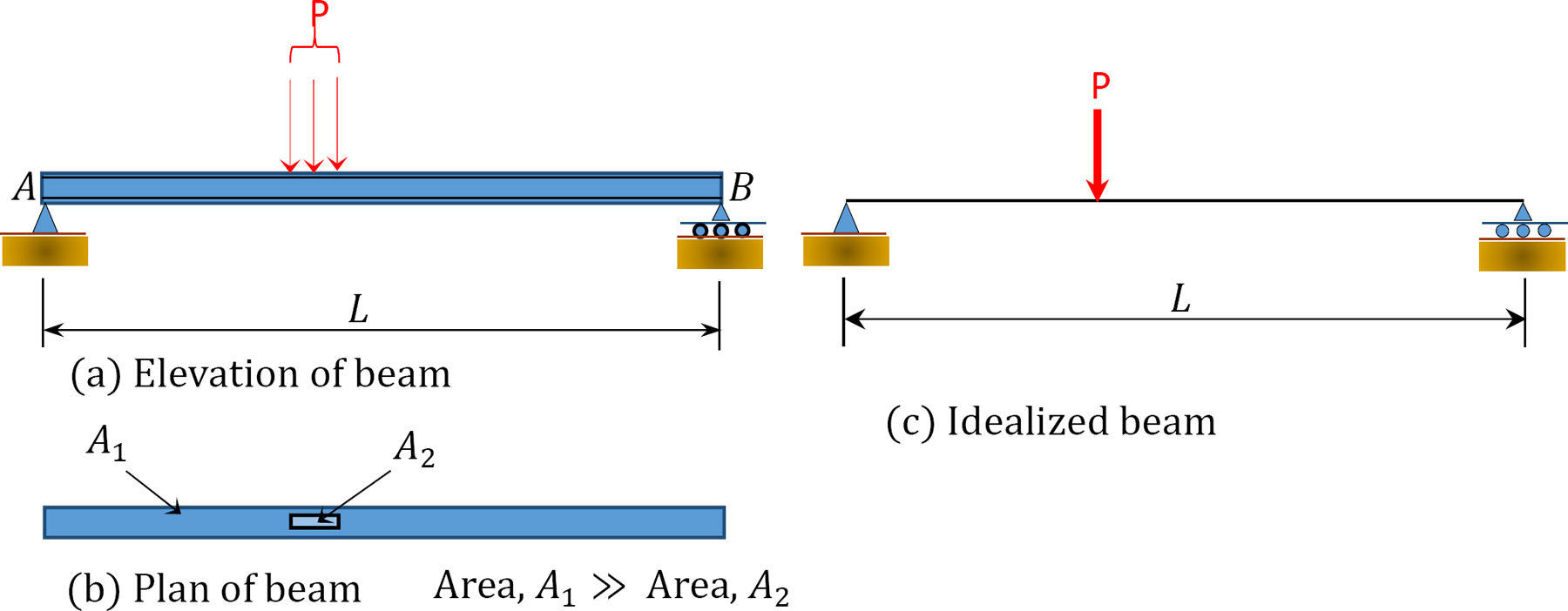
\(Fig. 1.9\). Wide – flange beam idealization.
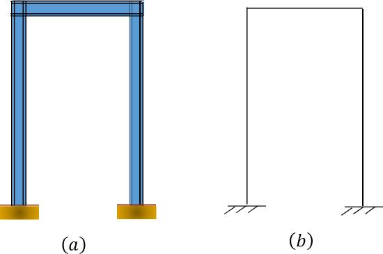
\(Fig. 1.10\). Frame idealization.
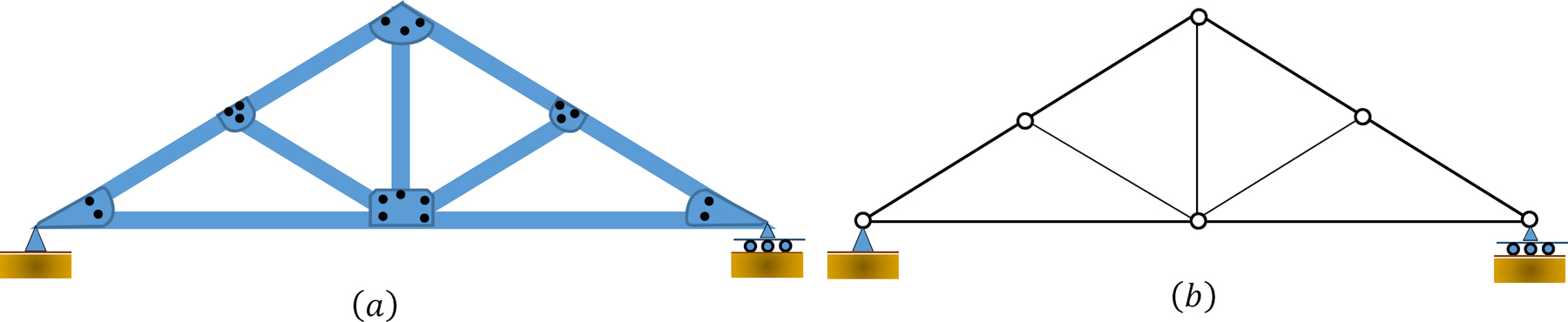
\(Fig. 1.11\). Truss idealization.
Method of Sections
The method of sections is useful when determining the internal forces in structural members that are in equilibrium. The method involves passing an imaginary section through the structural member so that it divides the structure into two parts. Member forces are determined by considering the equilibrium of either part. For a beam in equilibrium that is subjected to transverse loading, as shown in Figure 1.12, the internal forces include an axial or normal force, \(N\), shear force, \(V\), and bending moments, \(M\).
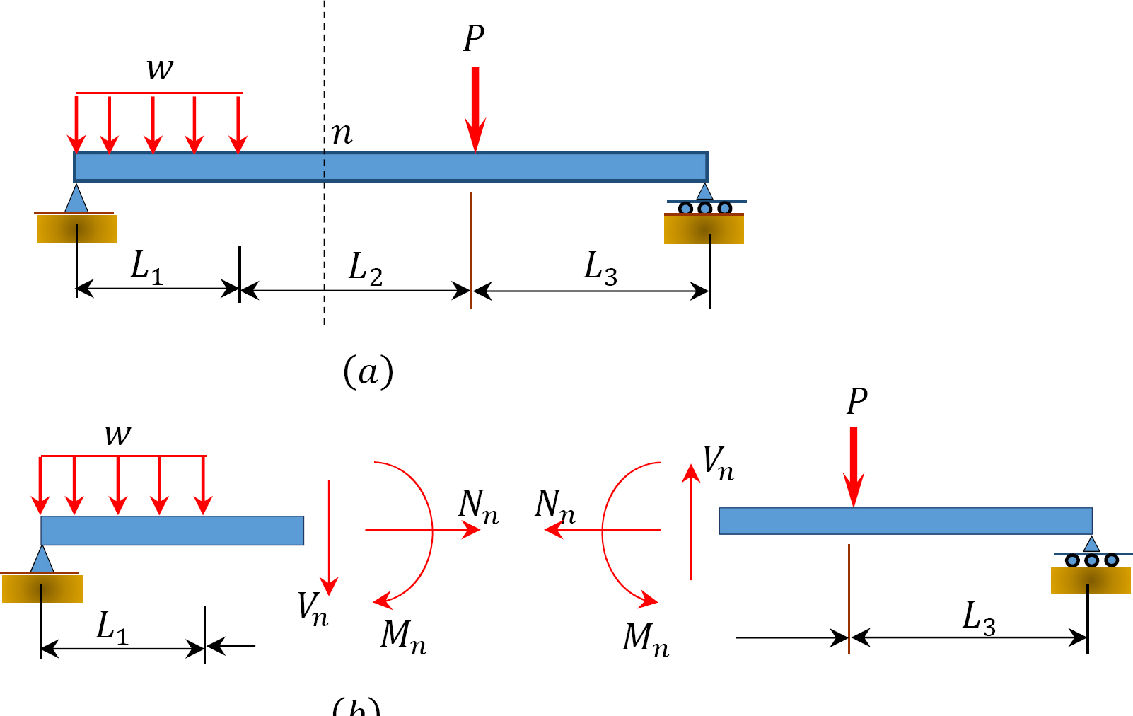
\(Fig. 1.12\). Beam in equilibrium subjected to transverse loading.
1.3.8 Free-Body Diagram
A free-body diagram is a diagram showing all the forces and moments acting on the whole or a portion of a structure. A free-body diagram must also be in equilibrium with the actual structure. The free-body diagram of the entire beam shown in Figure 1.13a is depicted in Figure 1.13b. If the free-body diagram of a segment of the beam is desired, the segment will be isolated from the entire beam using the method of sections. Then, all the external forces on the segment and the internal forces from the adjoining part of the structure will be applied to the isolated part.
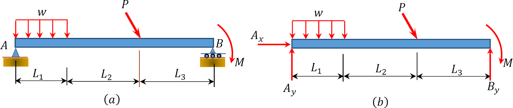
\(Fig. 1.13\) Free-body diagram of a beam.