
9.2: Influence Lines for Statically Determinate Beams by Static Equilibrium Method
- Page ID
- 42982

To grasp the basic concept of influence lines, consider the simple beam shown in Figure 9.1a. Statics help to determine the magnitude of the reactions at supports \(A\) and \(B\), and the shearing force and bending moment at a section \(n\), as a unit load of arbitrary unit, moves from right to left.
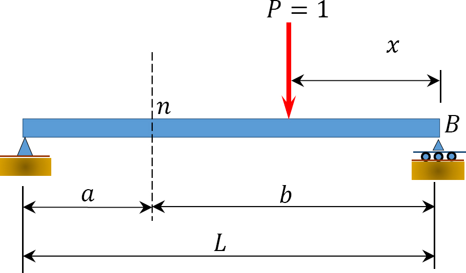
\(Fig. 9.1a\). Simple beam.
9.2.1 Beam Reactions
Taking the moment about \(B\) as the unit load moves a distance \(x\) from the right-hand end suggests the following:
\[\begin{array}{c}
+\sum M_{B}=0 \\
-R_{A} L+P x=0 \\
R_{A}=\frac{p x}{L}
\end{array}\]
Setting \(P = 1\) suggests the following:
\[R_{A}=\frac{x}{L}\]
Equation 9.2 is the expression for the computation of the influence line for the left-end reaction of a simply supported beam. The influence line for \(R_{A}\) can be represented graphically by putting some values of \(x\) into the equation. Since the equation is linear, two points should be enough.
When \(x=0\), \(R_{A}=0\)
When \(x=L\), \(R_{A}=1\)
The graphical representation of the influence line for \(R_{A}\) is shown in Figure 9.1b, and the ordinate of the diagram corresponding to any value of \(x\) gives the magnitude of \(R_{A}\) at that point.
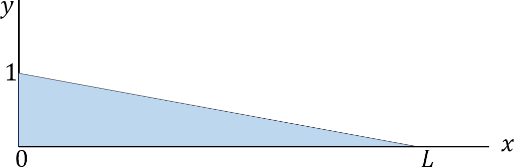
\(Fig. 9.1b\). Influence line for \(R_{A}\).
Similarly, the expression for the influence line for the reaction \(R_{B}\) is found by taking the moment about \(A\).
\[\begin{array}{l}
\sum M_{A}=0 \\
R_{B} L-P(L-x)=0 \\
R_{B}=\frac{P(L-x)}{L}
\end{array}\]
Setting \(P = 1\) into equation 9.3 suggests the following:
\[R_{B}=\frac{(L-x)}{L}\]
Equation 9.4 is the expression for the computation of the influence line for the right-end reaction of a simply supported beam. Substituting some values for x into the equation helps to construct the influence line diagram for \(R_{B}\).
When \(x=0\), \(R_{B}=1\)
When \(x = L\), \(R_{B} = 0\)
The graphical representation of the influence line for \(R_{B}\) is shown in Figure 9.1c.
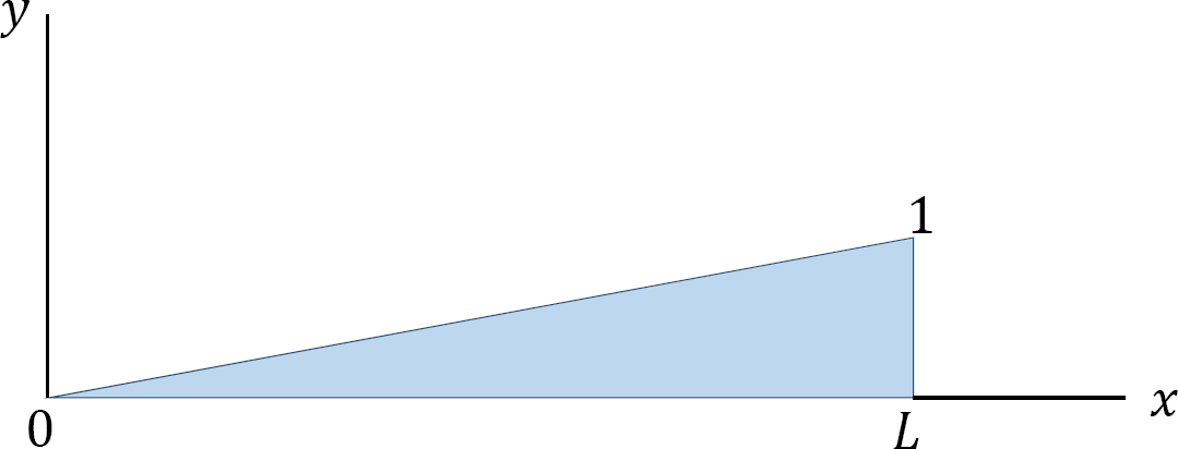
\(Fig. 9.1c\). Influence line for \(R_{B}\).
9.2.2 Shearing Force at Section \(n\)
When the unit load is on the right side of the section, the shear force at the section can be computed considering the transverse forces on the left side of the section, as follows:
\(\begin{array}{l}
\text { Shearing force, } V=R_{A}=\frac{x}{L} \\
\text { When } x=0, V=0 \\
\text { When } x=b, V=\frac{b}{L}
\end{array}\)
When the unit load is on the left side of the section, it is easier to compute the shear force in the section by considering the forces on the right side of section, as follows:
\(\begin{array}{l}
V=-R_{B}=-\frac{(L-x)}{L} \\
\text { When } x=b, V=-\frac{(L-b)}{L}=-\frac{a}{L} \\
\text { When } x=L, V=0
\end{array}\)
The graphical representation of the influence line for the shearing force at a section \(n\) of the simple beam is shown in Figure 9.1d.
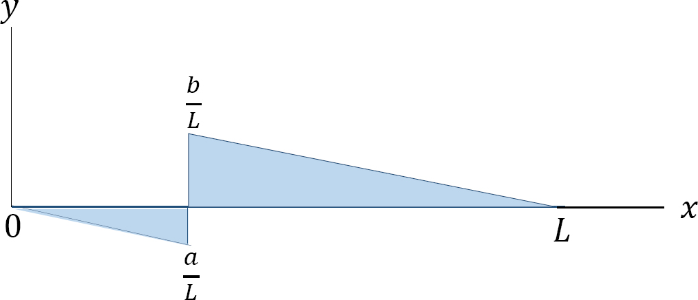
\(Fig. 9.1d\). Influence line for shear at section \(n\).
9.2.3 Bending Moment at a Section \(n\)
When the unit load is on the right side of the section, the bending moment at the section can be computed as follows:
\(\begin{array}{l}
M=R_{A}(L-x)=\frac{x}{L}(a) \\
\text { When } x=0, M=0 \\
\text { When } x=b, M=\frac{a b}{L}
\end{array}\)
When the unit load is on the left side of section, the bending moment at the section can be computed as follows:
\(\begin{array}{l}
M=R_{B} x=\frac{(L-x)}{b} x \\
\text { When } x=0, M=0 \\
\text { When } x=b, M=\frac{a b}{L}
\end{array}\)
The graphical representation of the influence line for the bending moment at a section \(n\) of the simple beam is shown in Figure 9.1e.
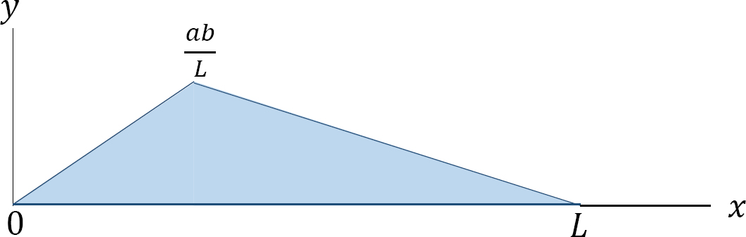
\(Fig. 9.1e\) . Influence line for moment at section \(n\).