
2.3: Degrees-of-Freedom
- Page ID
- 14776

\( \newcommand{\vecs}[1]{\overset { \scriptstyle \rightharpoonup} {\mathbf{#1}} } \)
\( \newcommand{\vecd}[1]{\overset{-\!-\!\rightharpoonup}{\vphantom{a}\smash {#1}}} \)
\( \newcommand{\dsum}{\displaystyle\sum\limits} \)
\( \newcommand{\dint}{\displaystyle\int\limits} \)
\( \newcommand{\dlim}{\displaystyle\lim\limits} \)
\( \newcommand{\id}{\mathrm{id}}\) \( \newcommand{\Span}{\mathrm{span}}\)
( \newcommand{\kernel}{\mathrm{null}\,}\) \( \newcommand{\range}{\mathrm{range}\,}\)
\( \newcommand{\RealPart}{\mathrm{Re}}\) \( \newcommand{\ImaginaryPart}{\mathrm{Im}}\)
\( \newcommand{\Argument}{\mathrm{Arg}}\) \( \newcommand{\norm}[1]{\| #1 \|}\)
\( \newcommand{\inner}[2]{\langle #1, #2 \rangle}\)
\( \newcommand{\Span}{\mathrm{span}}\)
\( \newcommand{\id}{\mathrm{id}}\)
\( \newcommand{\Span}{\mathrm{span}}\)
\( \newcommand{\kernel}{\mathrm{null}\,}\)
\( \newcommand{\range}{\mathrm{range}\,}\)
\( \newcommand{\RealPart}{\mathrm{Re}}\)
\( \newcommand{\ImaginaryPart}{\mathrm{Im}}\)
\( \newcommand{\Argument}{\mathrm{Arg}}\)
\( \newcommand{\norm}[1]{\| #1 \|}\)
\( \newcommand{\inner}[2]{\langle #1, #2 \rangle}\)
\( \newcommand{\Span}{\mathrm{span}}\) \( \newcommand{\AA}{\unicode[.8,0]{x212B}}\)
\( \newcommand{\vectorA}[1]{\vec{#1}} % arrow\)
\( \newcommand{\vectorAt}[1]{\vec{\text{#1}}} % arrow\)
\( \newcommand{\vectorB}[1]{\overset { \scriptstyle \rightharpoonup} {\mathbf{#1}} } \)
\( \newcommand{\vectorC}[1]{\textbf{#1}} \)
\( \newcommand{\vectorD}[1]{\overrightarrow{#1}} \)
\( \newcommand{\vectorDt}[1]{\overrightarrow{\text{#1}}} \)
\( \newcommand{\vectE}[1]{\overset{-\!-\!\rightharpoonup}{\vphantom{a}\smash{\mathbf {#1}}}} \)
\( \newcommand{\vecs}[1]{\overset { \scriptstyle \rightharpoonup} {\mathbf{#1}} } \)
\(\newcommand{\longvect}{\overrightarrow}\)
\( \newcommand{\vecd}[1]{\overset{-\!-\!\rightharpoonup}{\vphantom{a}\smash {#1}}} \)
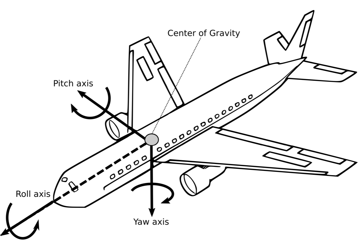
\(\newcommand{\avec}{\mathbf a}\) \(\newcommand{\bvec}{\mathbf b}\) \(\newcommand{\cvec}{\mathbf c}\) \(\newcommand{\dvec}{\mathbf d}\) \(\newcommand{\dtil}{\widetilde{\mathbf d}}\) \(\newcommand{\evec}{\mathbf e}\) \(\newcommand{\fvec}{\mathbf f}\) \(\newcommand{\nvec}{\mathbf n}\) \(\newcommand{\pvec}{\mathbf p}\) \(\newcommand{\qvec}{\mathbf q}\) \(\newcommand{\svec}{\mathbf s}\) \(\newcommand{\tvec}{\mathbf t}\) \(\newcommand{\uvec}{\mathbf u}\) \(\newcommand{\vvec}{\mathbf v}\) \(\newcommand{\wvec}{\mathbf w}\) \(\newcommand{\xvec}{\mathbf x}\) \(\newcommand{\yvec}{\mathbf y}\) \(\newcommand{\zvec}{\mathbf z}\) \(\newcommand{\rvec}{\mathbf r}\) \(\newcommand{\mvec}{\mathbf m}\) \(\newcommand{\zerovec}{\mathbf 0}\) \(\newcommand{\onevec}{\mathbf 1}\) \(\newcommand{\real}{\mathbb R}\) \(\newcommand{\twovec}[2]{\left[\begin{array}{r}#1 \\ #2 \end{array}\right]}\) \(\newcommand{\ctwovec}[2]{\left[\begin{array}{c}#1 \\ #2 \end{array}\right]}\) \(\newcommand{\threevec}[3]{\left[\begin{array}{r}#1 \\ #2 \\ #3 \end{array}\right]}\) \(\newcommand{\cthreevec}[3]{\left[\begin{array}{c}#1 \\ #2 \\ #3 \end{array}\right]}\) \(\newcommand{\fourvec}[4]{\left[\begin{array}{r}#1 \\ #2 \\ #3 \\ #4 \end{array}\right]}\) \(\newcommand{\cfourvec}[4]{\left[\begin{array}{c}#1 \\ #2 \\ #3 \\ #4 \end{array}\right]}\) \(\newcommand{\fivevec}[5]{\left[\begin{array}{r}#1 \\ #2 \\ #3 \\ #4 \\ #5 \\ \end{array}\right]}\) \(\newcommand{\cfivevec}[5]{\left[\begin{array}{c}#1 \\ #2 \\ #3 \\ #4 \\ #5 \\ \end{array}\right]}\) \(\newcommand{\mattwo}[4]{\left[\begin{array}{rr}#1 \amp #2 \\ #3 \amp #4 \\ \end{array}\right]}\) \(\newcommand{\laspan}[1]{\text{Span}\{#1\}}\) \(\newcommand{\bcal}{\cal B}\) \(\newcommand{\ccal}{\cal C}\) \(\newcommand{\scal}{\cal S}\) \(\newcommand{\wcal}{\cal W}\) \(\newcommand{\ecal}{\cal E}\) \(\newcommand{\coords}[2]{\left\{#1\right\}_{#2}}\) \(\newcommand{\gray}[1]{\color{gray}{#1}}\) \(\newcommand{\lgray}[1]{\color{lightgray}{#1}}\) \(\newcommand{\rank}{\operatorname{rank}}\) \(\newcommand{\row}{\text{Row}}\) \(\newcommand{\col}{\text{Col}}\) \(\renewcommand{\row}{\text{Row}}\) \(\newcommand{\nul}{\text{Nul}}\) \(\newcommand{\var}{\text{Var}}\) \(\newcommand{\corr}{\text{corr}}\) \(\newcommand{\len}[1]{\left|#1\right|}\) \(\newcommand{\bbar}{\overline{\bvec}}\) \(\newcommand{\bhat}{\widehat{\bvec}}\) \(\newcommand{\bperp}{\bvec^\perp}\) \(\newcommand{\xhat}{\widehat{\xvec}}\) \(\newcommand{\vhat}{\widehat{\vvec}}\) \(\newcommand{\uhat}{\widehat{\uvec}}\) \(\newcommand{\what}{\widehat{\wvec}}\) \(\newcommand{\Sighat}{\widehat{\Sigma}}\) \(\newcommand{\lt}{<}\) \(\newcommand{\gt}{>}\) \(\newcommand{\amp}{&}\) \(\definecolor{fillinmathshade}{gray}{0.9}\)The concept of degrees-of-freedom, often abbreviated as DOF, is important for defining the possible positions and orientations a robot can reach. An object in the physical world can have up to six degrees of freedom, namely forward/backward, sideways, and up/down as well as rotations around those axes. These rotations are known as pitch, yaw and roll and are illustrated in Figure 2.3.1.
How many of those directions a robot can move in depends on the configuration of its actuators and the constraints the robot has with the environment. These relationships are not always intuitive and require more rigorous mathematical treatment (Chapter 3). The goal of this section is to introduce the degrees of freedom of standard mechanisms that are recurrent in robot design such as wheels or simple arms. For wheeled platforms, the degrees-of-freedom are defined by the types of wheels used and their orientation. Common wheel types are listed in Table 2.3.1.
Only robots that use exclusively wheels with three degrees-offreedom (3-DOF wheels) will be able to freely move on a plane. This is because the pose of a robot on a plane is fully given by its position (two values) and its orientation (one value). Robots that don’t have wheels with three degrees of freedom will have kinematic constraints that prevent them from reaching every possible point at every possible orientation. For example, a bicycle wheel can only roll into one direction and turn on the spot. Moving the bicycle wheel orthogonal to its direction of rolling is not possible, unless it is forcefully dragged (“skidding”), which requires more involved treatment not covered in this book. On the other hand, not having three degrees of freedom does not mean that not all poses in the plane can be reached. A good analogue are figures on a chess-board. For example, a knight can reach every cell on a chess-board but might require multiple moves to do so. This is similar to a car, which can parallel park using back-and-forth motions. Instead, a bishop can only reach either black or white fields on the board.
| Wheel Type | Example | Degrees-of-Freedom |
|
Standard
|
Front-wheel of a wheelbarrow |
Two
|
|
Caster wheel
|
Office chair |
Three
|
|
Swedish wheel
|
Standard wheel with non-actuated rollers around its circumference |
Three
|
|
Spherical wheel
|
Ball Bearing |
Three
|
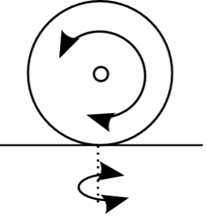
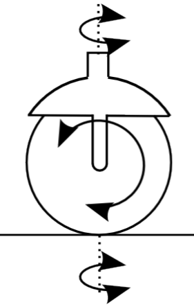
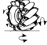
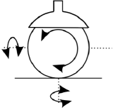
Table \(\PageIndex{1}\): Different types of wheels and their degrees of freedom. Adopted from Siegwart et al. (2011),
Similar reasoning applies to aerial and underwater robots. Here, the position of the robot is affected by the position and orientation of thrusters, either in the form of jets or propellers, mounted on the robot. Things become complicated quickly, however, as the dynamics of the system are subject to fluidand aerodynamic effects, which also change as a function of size of the robot. This book will not go into the details of flying and swimming robots, but the general principles of localization and planning will be applicable to them as well.
Query
Think about possible wheel, propeller and thruster configurations. Don’t limit yourself to robots, but consider also street and aerial vehicles and be creative — if you can think about a setup that makes sense, i.e., allows for reasonable mobility — somebody will already have built it and analyzed it. What are the advantages and disadvantages of each?
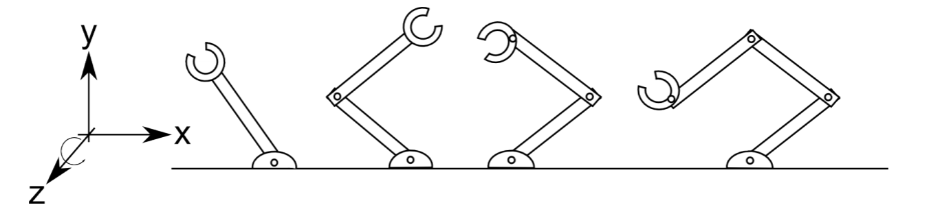
For manipulating arms, degrees of freedom usually refer to the positions and orientations, i.e., rotations around the primary axes, the end-effector can reach. As a rule of thumb, each joint usually adds a degree of freedom unless they are redundant, that is, moving in the same direction. Figure 2.4 shows a series of manipulators operating in a plane. By this, the degrees of freedom of the end-effector are limited to moving up and down, sideways, and rotating around its pivot point. As a plane only has those three degrees of freedom, adding additional joints cannot increase the degrees of freedom unless they allow the robot to also move in and out of the plane.
An exact definition of the number of degrees of freedom is tricky and requires deriving analytical expressions for the endeffector position and orientation, which will be subject to Chapter 3.
Choosing the “right” kinematics is a trade-off between mechanical complexity, maneuverability, achievable precision, cost, and ease of control. The very popular differential-wheel drive consisting of two independently controlled wheels that share a common axis such as on the iRobot Roomba is cheap, highly maneuverable and easy to control, but makes it hard to drive in a straight line. This requires both motors to turn at the exact same speed and both wheels to have the exact same diameter, which is hard to achieve in practice. This problem is solved well by car-like steering mechanisms, but they have poor maneuverability and are difficult to control (think parallel-parking).